

Amplitude modulation (AM) was first introduced to enable long-range wireless audio communication, representing a major advancement over wireless telegraphy using spark-gap transmitters. Understanding what is amplitude modulation and how it works is fundamental for electronics engineering students and professionals working with radio frequency circuits. This comprehensive guide covers amplitude modulation theory, circuit design, practical implementation, and real-world testing results with oscilloscope demonstrations.
Speaking about modulation, in simple terms, it's the method used to impose the message signal on a carrier signal, which is then transmitted by antenna or wire. And demodulation is practically the exact opposite, where the message signal is extracted from the carrier wave and used. In this article, we are going to learn about modulation and more about amplitude modulation with a practical circuit implementation.
Table of Contents
- Modulation and Its Types
- Amplitude Modulation Theory
- How Does Amplitude Modulation Work? Step-by-Step Process
- Amplitude Modulation Waveform
- Amplitude Modulation Advantages and Disadvantages
- Amplitude Modulation Practical Demonstration
- Amplitude Modulation Circuit Diagram
- Amplitude Modulation FAQ - Common Questions Answered
- DIY Projects on Wireless Audio Transmission
Modulation and Its Types
Modulation is the process of adding information, like sound or data, to a high-frequency signal called a carrier wave so it can travel long distances or be sent more efficiently through wires or the air. Even though modulation itself looks simple, there are three main methods of modulation. They are:
Amplitude Modulation
Frequency Modulation
Phase Modulation
Below you can see a simple comparison chart that explains the basic differences between each type of modulation technique:
And remember that there are still more types of modulation available, like Pulse Amplitude Modulation (PAM), Pulse Width Modulation (PWM), Pulse Position Modulation (PPM), Frequency Shift Keying (FSK), Phase Shift Keying (PSK), Quadrature Amplitude Modulation (QAM), and more, as technology is getting improved day by day.
Amplitude Modulation Theory
Amplitude Modulation (AM) is a method of sending information, like voice or music, by changing the strength (amplitude) of a high-frequency carrier wave based on the input signal. It allows us to transmit audio over long distances using radio waves and forms the foundation of AM radio broadcasting systems.
So, you need to understand the meaning of amplitude first to understand AM clearly.
Amplitude of a Signal
In simple terms, amplitude is how strong or intense a wave is. It's plotted on a graph with time on the x-axis and amplitude on the y-axis. It's how loud the sound wave is, think of it as more volume, more sound, more amplitude.

It's usually measured in volts (V) for electrical signals, decibels (dB) for sound, or other units depending on the context.
Frequency of a Signal
Frequency is the number of times a wave with the same pattern repeats itself in one second. It tells us how fast a wave is vibrating. For example, a frequency of 50 Hz means the wave cycles 50 times every second.
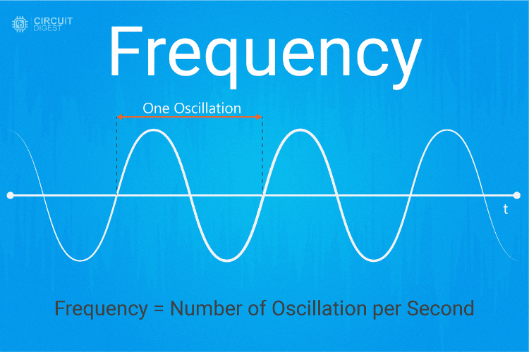
It's usually measured in Hertz (Hz). Now let's take a deeper look at amplitude modulation and understand how it works step by step.
How Does Amplitude Modulation Work? Step-by-Step Process
Understanding how amplitude modulation works step by step is crucial for electronics engineers and students. The AM process involves three main stages: carrier wave generation, message signal preparation, and the modulation process itself. Here's how amplitude modulation works in practice:
Carrier Wave Generation: A high-frequency sine wave (typically 535 kHz to 1700 kHz for AM radio) is generated using an oscillator circuit like the ICL8038 or similar function generator.
Message Signal Input: The audio or data signal that contains the information to be transmitted is prepared and amplified to appropriate levels.
Modulation Process: The amplitude of the carrier wave is varied according to the instantaneous amplitude of the message signal using a modulator circuit.
Signal Combination: The modulated signal combines both the carrier frequency and the message information in a single waveform.
Transmission: The modulated signal is amplified and transmitted through an antenna for long-distance communication.
This step-by-step amplitude modulation process ensures that low-frequency audio signals can be transmitted over long distances by riding on high-frequency carrier waves.
Amplitude Modulation Waveform
Below, you can see the image that clearly illustrates the modulated wave along with the carrier wave and the message signal, showing how the AM waveform is formed.
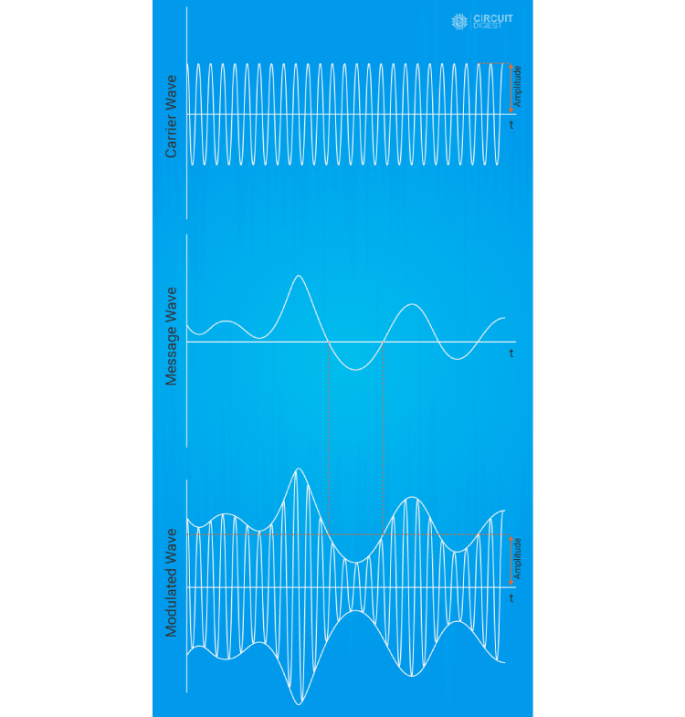
The first wave shown is the carrier signal.
In the case of AM radio, the carrier signal will be a medium-frequency wave, typically from 535 kHz to 1700 kHz. This carrier signal is generally a pure sine wave, generated using a dedicated oscillator circuit.
The next wave is a simple example message signal for demonstration. In this message wave, there is no specific frequency or amplitude. It's all random, which is how a real message would be. But the only thing is that the frequency of the message signal will be lesser than the carrier wave frequency.
Now, in the third modulated signal, you can see that the amplitude of the upper side of the carrier signal looks exactly like the message signal. This is how amplitude modulation works. In general, this effect can be achieved easily using a single transistor, where the carrier wave is amplified with respect to the input message signal, just like that.
AM Signal Equation Explained
The amplitude modulation formula derivation starts with understanding how the message signal modifies the carrier amplitude. This AM signal equation explained below shows the mathematical relationship between carrier, message, and modulated signals:
s(t)=[Ac+m(t)]cos(2πfct)
Here,
s(t): Refers to the modulated signal as a function of time. Sometimes this modulated signal is also represented as v(t), which is more specific as a voltage signal and is mostly used in circuit analysis. In general, this modulated signal can be represented as s(t).
Ac: Refers to the amplitude of the carrier wave that is used.
fc: Refers to the frequency of the carrier wave.
m(t): Refers to the modulating message signal as a function of time.
Amplitude Modulation Formula Derivation Explained
To understand the amplitude modulation formula derivation, let's break down each component. The modulation index (m) is a crucial parameter that determines the depth of modulation and can be calculated as m = Am/Ac, where Am is the amplitude of the message signal and Ac is the carrier amplitude. For proper AM transmission without distortion, the modulation index should not exceed 1 (100% modulation).
The complete AM formula derivation shows that the modulated signal contains the original carrier frequency plus upper and lower sidebands that carry the actual information. This mathematical foundation is essential for understanding how AM modulator circuits work in practice.
Now let's get into a practical demonstration for clear understanding.
Amplitude Modulation Advantages and Disadvantages
When designing AM circuits, it's important to understand the advantages and disadvantages of amplitude modulation compared to other modulation techniques like FM and digital modulation:
Advantages of Amplitude Modulation:
Simple circuit design and low-cost implementation compared to FM circuits
Easy demodulation using simple diode detectors without complex circuitry
Good long-range transmission capabilities, especially during nighttime propagation
Minimal bandwidth requirements (bandwidth = 2 × message signal bandwidth)
Mature technology with well-established manufacturing processes
Compatible with low-cost receivers, making it accessible worldwide
Disadvantages of Amplitude Modulation:
Poor noise immunity compared to FM and digital modulation techniques
Lower power efficiency due to continuous carrier transmission (only 33% efficiency at 100% modulation)
Susceptible to atmospheric interference and electrical noise
Limited audio quality compared to modern FM and digital broadcasting
Fading effects during long-distance transmission can cause signal degradation
Amplitude Modulation Practical Demonstration
To demonstrate amplitude modulation, we came up with a simple circuit using minimal components that you can try yourself.
Components Required
To keep this demonstration simple, I will be using commonly available components that are easy to find. Here's the complete list for building your own AM modulator circuit:
Below are the key components involved in the modulation process.
BC547 - 1 (Common NPN Transistor)
7805 - 1 (5v Voltage Regulator)
Resistor - 470Ω - 3
Resistor - 100Ω - 1
Resistor 1KΩ - 1
Capacitor - 470nF-2
Capacitor - 10pF-1
Modules
These modules are added only to reduce the complexity of the circuit used for testing amplitude modulation. With these, two major complexities solved, the circuit for generating the carrier signal and the circuit for the microphone setup for the message signal.
ICL8083 - 1(For Carrier Signal Generation)
Bluetooth Audio Receiver - 1(For message signal input)
Amplitude Modulation Circuit Diagram
Before getting into the actual circuit diagram, let's understand the basic working behind the circuit diagram.
How to Build AM Modulator Circuit - Step by Step Guide
The image below shows the basic concept behind amplitude modulation. Depending on the real-time application, there might be some upgrades, but the core concept remains the same.
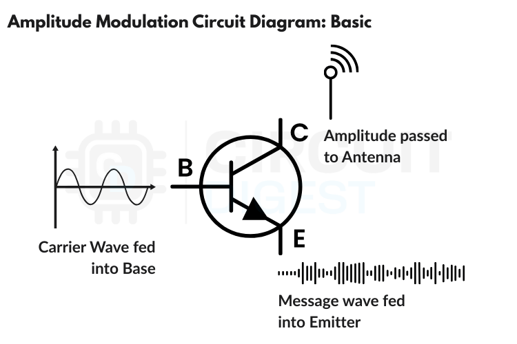
This amplitude modulation circuit design using BC547 transistor is perfect for students learning how to build AM modulator circuits. The circuit demonstrates the fundamental principle of AM generation and can be easily replicated on a breadboard. For beginners wondering how to make amplitude modulation circuit at home, this design uses commonly available components and provides clear, observable results on an oscilloscope.
The transistor acts like a variable amplifier controlled by two signals:
RF (Radio Frequency) input that comes from the oscillator (the medium-frequency carrier wave), and
Audio input that comes from a music source (like a computer, phone, or microphone).
The transistor works like an automatic volume control. As the audio signal gets louder, it makes the radio signal stronger. When the audio gets quieter, it makes the radio signal weaker.
This creates a modified radio signal where:
The frequency stays the same (like the radio station's channel),
The strength (amplitude) changes to match the message audio.
Any AM radio can detect these strength changes and convert them back into sound, simply by reversing the process.
Schematics of the AM Modulator
As you already know, to reduce the complexity, we are using separate modules for generating the carrier wave and feeding the message signal.
To clearly understand how the carrier wave is generated using the ICL8038, I recommend visiting the article: "How to Configure the ICL8038 to Generate a Sine Wave?" In our case, the only thing you need to know is that we power the ICL8038 module with 12V to ensure a higher frequency output.

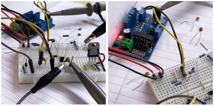
In the above circuit diagram, you can clearly see the complete layout.
The generated sine wave (carrier wave) is fed into the base of the transistor with the help of a coupling capacitor. The base is also stabilized using two biasing resistors of 470Ω each.
For the message signal, we're using a simple, inexpensive Bluetooth audio receiver, the same module used in the project , Simple DIY Wireless Bluetooth Speakers using Audio Amplifier.
The audio output of the Bluetooth module is connected to the emitter of the transistor using a coupling capacitor. And that's it, most of the circuit is ready!
In practical AM transmitter circuits, a dedicated RF amplifier stage is added before the antenna. In simpler circuits, a small capacitor is used to block DC while allowing RF to pass, and sometimes a basic LC filter is used to reduce harmonics.
But in our case, since we're not using an AM receiver to test this setup and only want to observe it using an oscilloscope, we've added just a DC blocking capacitor at the output.
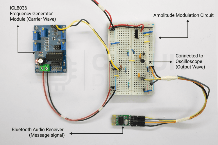
Powering the circuit is also important. I used a regulated power supply (RPS) to provide 12V to the entire circuit. This 12V powers both the ICL8038 module and the modulator transistor. A 7805 voltage regulator is used to provide 5V to the Bluetooth module.
Testing Our AM Modulator Setup
Testing was simple. I used my smartphone to send the message signal and an oscilloscope to verify the output and observe the amplitude modulation waveform in real time.
First, after connecting the breadboard to a 12V power supply, I checked for any faults.
I recommend you do the same, if the transistor is inserted with the wrong polarity, it may heat up quickly and its hFE (gain factor) could degrade over time.
Next, it was time to tune the carrier frequency on the ICL8038 module. I have set it to 380 kHz just as an example, you can set any high frequency of your choice for your AM modulator testing.
For precision, I used an oscilloscope to tune and verify the frequency.
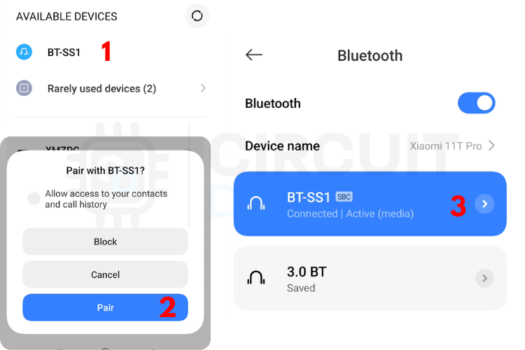
I opened the Bluetooth settings on my smartphone and paired it with the Bluetooth audio receiver. If you don't have a Bluetooth module, you can also use a simple AUX cable from your phone to extract the audio signal for amplitude modulation testing.
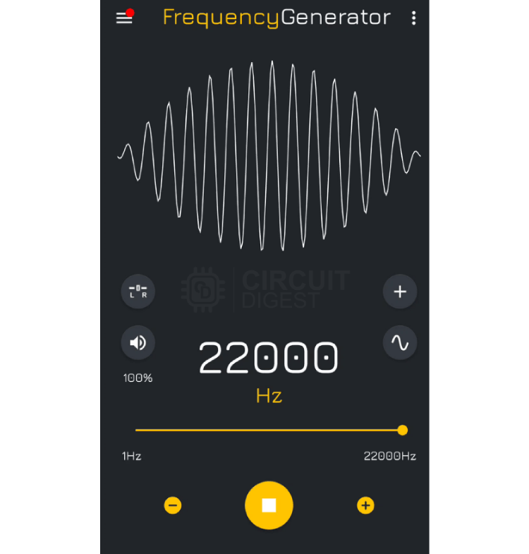
Next, I opened a frequency generator app. You can use any app for sound or even music. But for clearer oscilloscope visuals and better amplitude modulation demonstration, I chose to generate a stationary sine wave.
Using the app, I generated a 22 kHz sine wave and connected the second probe of the oscilloscope to the circuit's output to observe the amplitude modulation results.
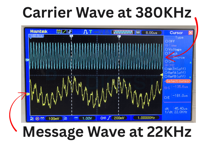
The oscilloscope display shows two important signals: the white trace (top) displays our 380 kHz carrier wave output from the AM modulator, while the yellow trace (bottom) shows the 22 kHz message signal from our phone app. The key observation is how the amplitude of the carrier wave (white) varies up and down following the exact pattern of the message signal (yellow), this varying envelope is amplitude modulation in action.
Notice how when the yellow message wave reaches its peak, the carrier amplitude becomes maximum, and when the message wave hits its lowest point, the carrier amplitude becomes minimum. This direct relationship proves our circuit is successfully impressing the audio information onto the high-frequency carrier wave. Please note that in the image above the carrier wave appears "inverted" due to our NPN transistor configuration, but this doesn't affect functionality.
This oscilloscope result confirms perfect amplitude modulation, the carrier frequency stays constant at 380 kHz while its amplitude varies according to our 22 kHz message signal. Any AM radio tuned to 380 kHz would detect these amplitude changes and convert them back into the original 22 kHz audio tone, demonstrating how AM radio communication works in practice.
Amplitude Modulation Circuit Troubleshooting Guide
When building your own AM modulator circuit, you might encounter some common issues. Here's a comprehensive troubleshooting guide for amplitude modulation circuits that will help you identify and fix problems quickly:
Common AM Circuit Problems and Solutions:
No Output Signal: Check power supply connections (ensure 12V is reaching ICL8038 and transistor), verify transistor orientation (BC547 pinout: CBE from left), and confirm all ground connections are secure
Distorted Modulation: Reduce message signal amplitude using volume control, check biasing resistor values (470Ω resistors), and ensure carrier frequency is much higher than audio frequency
Weak Carrier Signal: Verify ICL8038 module connections and power supply, adjust frequency control potentiometer, and check coupling capacitor connections
Overmodulation (Signal Clipping): Reduce audio input level from smartphone or Bluetooth module, check transistor biasing point, and ensure adequate power supply current
Poor Modulation Depth: Increase audio signal amplitude carefully, verify emitter coupling capacitor (470nF), and check transistor gain (hFE should be >100)
Oscilloscope Shows No Modulation: Ensure both carrier and audio signals are present, check probe ground connections, and verify oscilloscope trigger settings
AM Circuit Testing Tips:
Always test carrier signal first before adding audio input
Use low audio frequencies (100Hz-1kHz) for initial testing
Monitor transistor temperature - it shouldn't get hot during normal operation
Start with low modulation depth and gradually increase
Amplitude Modulation FAQ - Common Questions Answered
What is the difference between AM and FM modulation?
The main difference between AM and FM modulation is that AM (Amplitude Modulation) varies the amplitude of the carrier wave while keeping frequency constant, whereas FM (Frequency Modulation) varies the frequency while keeping amplitude constant. AM has simpler circuits and better long-range propagation but lower noise immunity compared to FM. AM radio operates in 535-1700 kHz band while FM radio uses 88-108 MHz band.
Why is amplitude modulation still used today?
Amplitude modulation is still used in AM radio broadcasting, aviation communications, and amateur radio because of its simplicity, excellent long-range propagation characteristics (especially at night), and the low cost of AM receivers. Many developing countries rely on AM radio for information dissemination due to its cost-effectiveness and simple receiver design.
What components are needed for a basic AM transmitter?
A basic AM transmitter requires an oscillator for carrier generation (like ICL8038), a modulator circuit (often using a transistor like BC547), an audio amplifier for the message signal, coupling capacitors, biasing resistors, and an RF amplifier stage before the antenna. Our demonstration uses BC547 transistor, ICL8038 module, resistors, capacitors, and basic passive components for a complete working AM modulator.
How do you calculate modulation index in amplitude modulation?
The modulation index (m) in amplitude modulation is calculated as m = Am/Ac, where Am is the amplitude of the message signal and Ac is the carrier signal amplitude. For undistorted transmission, the modulation index should not exceed 1 (100% modulation). Values above 1 cause overmodulation and signal distortion.
What is the bandwidth of an AM signal?
The bandwidth of an AM signal is twice the highest frequency of the modulating message signal. For example, if the audio signal has a maximum frequency of 5 kHz, the AM signal bandwidth will be 10 kHz. This is much narrower than FM signals, making AM more spectrum-efficient.
Can I build an AM radio transmitter legally?
Building AM transmitters for educational purposes is generally allowed, but transmitting signals over certain power levels requires licensing from your country's telecommunications authority. Always check local regulations before building and operating any radio transmitter. Low-power educational demonstrations are typically permitted.
DIY Projects on Wireless Audio Transmission
Discover practical implementations of wireless audio communication with these projects, ranging from ESP32-based internet radio to advanced wireless audio transfer using nRF24L01 modules, Li-Fi, and even LEDs. These amplitude modulation related projects will help you understand various wireless communication techniques.

Wireless Audio Transfer Using LASER Light
Learn how to transmit audio wirelessly using laser light with this simple and innovative DIY project. Explore the circuit, components, and working of laser-based audio communication similar to amplitude modulation principles.

Simple DIY Wireless Bluetooth Speakers using Audio Amplifier
Build your own wireless Bluetooth speaker with this easy DIY project. Learn about the circuit design, components used, and step-by-step instructions for audio playback using Bluetooth technology - the same module used in our AM demonstration.

Arduino based Audio Spy Bug using NRF24L01
Learn how to build an Arduino-based wireless audio spy bug using the NRF24L01 module. This project demonstrates real-time audio transmission for surveillance and remote listening applications using digital modulation techniques.

Audio Transfer using Li-Fi Technology
Explore how to transfer audio wirelessly using Li-Fi technology in this project. Learn how LED light is used to transmit sound signals without radio frequencies, demonstrating optical modulation techniques similar to amplitude modulation concepts.

Long Range Arduino Based Walkie Talkie using nRF24L01
Build a simple Arduino-based walkie-talkie using the NRF24L01 module to enable two-way wireless audio communication over short distances using digital modulation instead of traditional AM techniques.

How to use nRF24L01 module with Arduino?
Learn how to interface the nRF24L01 wireless transceiver module with Arduino Uno for reliable, low-power wireless communication in your projects using advanced digital modulation techniques.

ESP32 Based Internet Radio using MAX98357A I2S Amplifier Board
Build an ESP32-based internet radio using the MAX98357A I2S amplifier board to stream music over Wi-Fi with clear audio output and easy controls, representing modern alternatives to traditional AM radio broadcasting.
