A generic AC fan regulator circuit is essentially used to vary the speed of the fan. In this project, we will build our own fan regulator with minimum components and for better efficiency. Generally, the fan generates a humming noise when brought to use with different fan regulator circuits, our circuit uses DIAC and a TRIAC and produces minimum to no humming noise and works like a charm! We also have designed multiple fan speed control circuits and also implemented IoT techniques to control them, go ahead and take a look at those amazing circuits for reference if you are interested.
Components Required to build an AC Fan Regulator
The components required to build a TRIAC fan regulator circuit are listed below:
- 500k ohm Potentiometer
- BT 136 TRIAC
- DB3 DIAC
- 0.1uf/400v Capacitor
- 10k ohm resistor
- 2 pin Terminal Block
Circuit Diagram for the AC Fan Regulator
The AC fan regulator circuit diagram is given below. The 220V AC mains voltage is given as the input to the one terminal of the fan (load) and the other terminal of the fan is connected to the one leg of the 10K ohm resistor. The 10K ohm resistor will be connected to the one terminal of the 500K ohm potentiometer, whereas the output terminal will be shorted and connected to the one pin of the DIAC and to the 0.1uF capacitor. (DIAC does not have a polarity, so it can be connected from any end). The DIAC’s other end-pin is connected to the Gate terminal of the TRIAC, which basically controls the ON and OFF state of the TRIAC. The 10K ohm resistor is connected to the MT2 pin of the TRIAC. The connection is quite simple and can be made over a perfboard. We can also design our own PCB board to house all the components easily.

Tip:
- Use a heat sink with the TRIAC as it may heat up after some time of its working or with high wattage appliances.
- Load capacity is <200 watts. If you wish to use a higher wattage load, use other variants of BTA TRIACs.
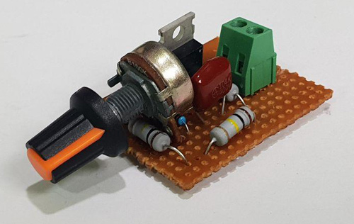
I have built this circuit on a zero PCB for testing it and my board after soldering all the components is looked like as shown in the image below. As you can see, the project looks simple and easy, so I would also recommend you to get your Veroboard and get started with it.
Quick Introduction for TRIAC and DIAC
The two main components used in the circuit are the TRIAC and the DIAC, let us quickly understand the basics of their working. You can also check out the detailed article on the working of TRIAC and the working of DIAC if you wish to explore more.
TRIAC: TRIACs are the components used in controlling the AC signals. They are used in multiple applications where high-power switching is required in AC waveforms. TRIACs are generally used in AC dimmer circuits and come in very handy when trying to control the speed of a fan or as a dimmer to the LED bulb.
DIAC: DIAC stands for Diodes for Alternating Current. It is a bi-directional component having two electrodes. It is another component of the Thyristor family. It only works when it surpasses its breakover voltage (VBO) and is usually used to trigger the TRIACs. The graph below depicts the working of a DIAC.
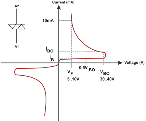
The waveform presented above depicts the current vs voltage graph of the DIAC. As we are aware that, in our project, DIAC is the component that is controlling the conducting phase of a TRIAC through its Gate terminal, we need to know how the breakover voltage (VBO) works in a DIAC. The DIAC only gets to its conducting stage once it crosses a barrier voltage (VBO) which is roughly around 30V but differs with different component models. Initially, DIAC is a device that has a higher resistance but after a continual increase in the voltage level and at the point of VBO, the resistance decreases drastically and it starts conducting which results in an increase in the current. The DIAC stays in its conducting state till the current drawn from it decreases to a level called ‘holding current’. Once the current drawn drops below the holding current, the DIAC becomes non conducting again.
As shown in the graph above, the voltage (x-axis) is gradually increased until it reaches its breakover voltage (VBO) which is 30-40V after which a sudden decrease is observed and constant current output is obtained (10mA) which is the holding current.
Difference between a TRIAC and a DIAC
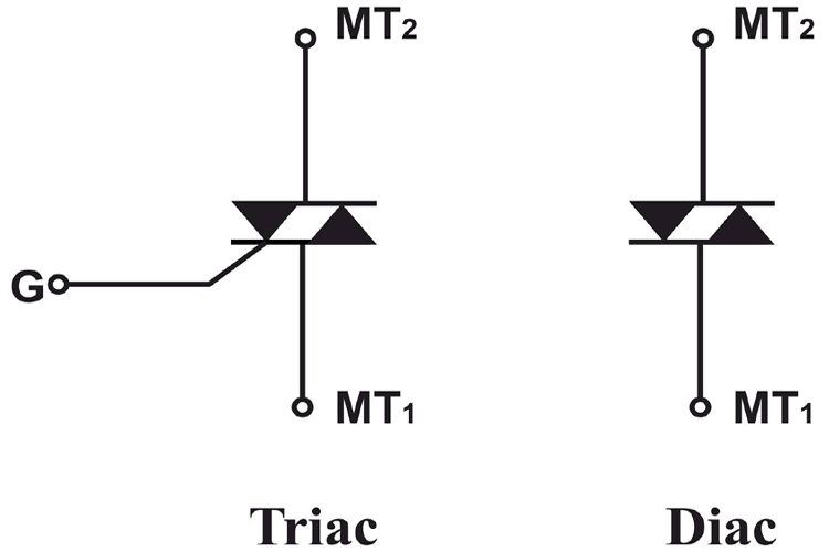
Despite the two devices being different in the number of pins and configuration, both DIAC and TRIAC belong to the Thyristor family. TRIAC is a high-power device, whereas a DIAC is considered being a low-power device. The Breakdown voltage (VBO) of the DIAC can not be altered whereas a TRIAC’s VBO can be altered using its gate terminal. DIAC is a device used to control the triggering point of the TRIAC. A typical pinout symbol for a TRIAC and DIAC is shown below.
Working of AC Fan Regulator Circuit
The circuit works mainly by controlling the gate terminal of the TRIAC and the other terminal of DIAC besides changing the discharge time of the capacitor. During the positive half of the cycle, the capacitor plates charge following a polarity, and the current also flows towards the T1 terminal of TRIAC, but the DIAC is still not triggered since we have not crossed the Breakover voltage (VBO) of the DIAC (usually around 30V for DB3. As the resistance is varied and the capacitor discharges to a voltage above the breakover voltage of the DIAC, the DIAC starts conducting and the output is given to the gate terminal of the TRIAC which is then triggered and the circuit is completed and the fan rotates.
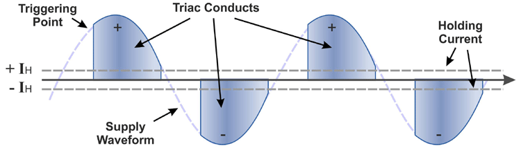
Similarly, for the negative half of the cycle the capacitor charges but with interchanged polarity, and once the breakover voltage is achieved (VBO), the DIAC conducts and triggers the TRIAC hence, the circuit gets completed. The graph above indicates the triggering and the conducting points and the triggering points along with the holding current (Ih) of the TRIAC during the full-wave AC signal.
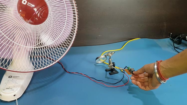
After completing the whole process of soldering and procuring the fan, I connected the module to the 220V AC voltage mains supply and the fan, whose speed is to be regulated. When I switched the supply ON and started to rotate the potentiometer, I noticed the fan rotating as per how much the potentiometer was rotated. The varying resistance of the potentiometer was aiding the fan speed to be regulated with the help of our TRIAC and DIAC.
Hope you have learnt something new and have enjoyed building your own AC Fan regulator. If you have any questions, leave them in the comment section or use our Electronics forum.
For explanation and to view the proper working of this project, kindly watch the video given below.

I need the hard copy documents of this project