

In this article, we are building an AC Fan Regulator Circuit, which is able to control the speed of the fan by restricting the flow of current to the fan. The term AC Ceiling Fan Regulator is a mouthful, hence we will simply call it a fan regulator from now on. A fan regulator circuit is a crucial component that is used to increase or decrease the speed of an AC Fan/motor according to needs. A few years back, you had a choice between a conventional resistive type fan regulator or an electronic regulator, but nowadays it's all been replaced by the electronic fan regulator circuit.
In a previous article, we have shown you how you could build an AC Phase Angle Control Circuit with an Arduino which was able to control the brightness of an incandescent light bulb and also control the speed of a Fan, so to step it up a notch in this article, we are going to build an IoT based AC Ceiling Fan Regulator circuit. Which will be able to control the speed of your ceiling fan with the help of an Android Application.
Working of an IoT based Ceiling Fan Regulator
The Fan Regulator circuit is a simple circuit that is able to control the speed of an AC ceiling fan by altering the phase angle of the AC sine wave or in simple terms precise control of the TRIAC. As I have mentioned all the basic workings of the AC fan regulator circuit in the AC Phase Angle Control with 555 Timer and PWM article, we will be concentrating on the actual building of the circuit. And again if you want to know more about the topic, please also check the article on AC Light Dimmer using Arduino and TRIAC Project.
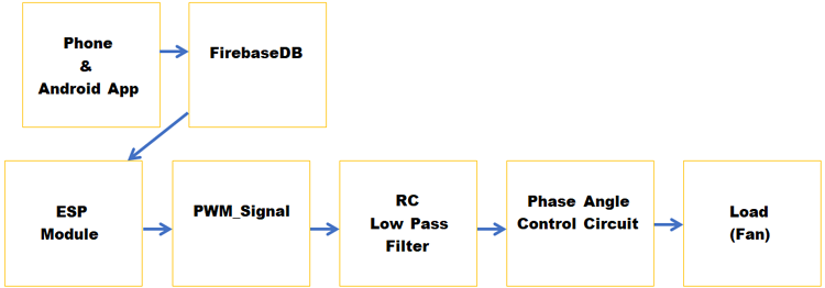
The basic block diagram above shows how the circuit actually works. As I have said earlier, we will generate a PWM signal with the help of the Firebase IoT and NodeMCU, then the PWM signal will be passed through the low-pass filter which will control the gate of a MOSFET after that a 555 timer will control the actual TRIAC with the help of an optocoupler.
In this case, the android app alters the value in the firebaseDB and the ESP is constantly checking for any changes that are happening to that DB if any change occurs that gets pulled down and the value is converted to a PWM signal
Materials Required for AC Fan Speed Control Circuit
The image below shows the material used to build this circuit, as this is made with very generic components, you should be able to find all of the listed material in your local hobby store.
I have also listed the components in a table below with type and quantity since its a demonstration project, I am using a single channel to do so. But the circuit can be easily scaled up as per requirement.
- Screw Terminal 5.04mm Connector - 2
- Male Header 2.54mm Connector - 1
- 56K, 1W Resistor - 2
- 1N4007 Diode - 4
- 0.1uF, 25V Capacitor - 2
- AMS1117 Voltage Regulator - 1
- 1000uF, 25V Capacitor - 1
- DC Power Jack - 1
- 1K Resistor - 1
- 470R Resistor - 2
- 47R Resistor - 2
- 82 K Resistors - 1
- 10 K Resistors - 5
- PC817 Optocoupler - 1
- NE7555 IC - 1
- MOC3021 Opto TriacDrive - 1
- IRF9540 MOSFET - 1
- 3.3uF Capacitor - 1
- Connecting Wires - 5
- 0.1uF, 1KV Capacitor - 1
- ESP8266 (ESP-12E) Microcontroller - 1
AC Fan Regulator Control Circuit
The schematic for the IoT fan regulator circuit is shown below, this circuit is very simple and uses generic components to achieve phase angle control.

This circuit is made up of very carefully designed components. I will go through each one and explain each block.
ESP8266 (ESP-12E)Wi-Fi Chip:
This is the first part of our circuit and it's the part where we have changed a lot of things, other parts stay exactly the same, i.e if you have followed the previous article.
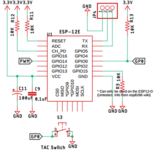
In this section, we have pulled up pins Enable, Reset, and GPIO0, also, we have pulled down GPIO15 and the Ground Pin, which are recommended by the datasheet of the chip. As for programming, we have placed a 3pin header exposing the TX, RX, and the ground pin through which we can program the chip very easily. Also, we have put a tactile switch to put the GPIO0 to ground, this is a necessary step to put the ESP in programming mode. We have selected the GPIO14 pin as output through which the PWM signal is generated.
Note! At the time of programming, we have to press the button and power the device with the DC barrel jack.
Zero-Crossing Detection Circuit:
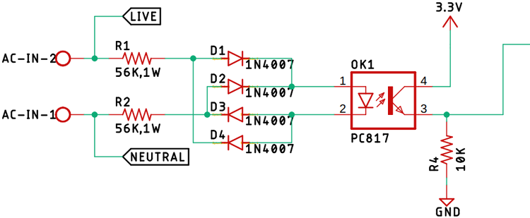
First, on our list is the zero-crossing detection circuit made with two 56K, 1W resistors in conjunction with four 1n4007 diodes and a PC817 optocoupler. And this circuit is responsible for providing the zero-crossing signal to the 555 timer IC. Also, we have taped off the phase and the neutral signal to further use it in the TRIAC section.
AMS1117-3.3V Voltage Regulator:
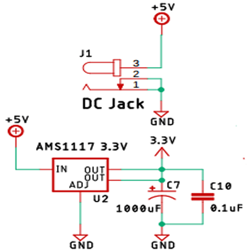
The AMS1117 voltage regulator is used to power the circuit, the circuit is responsible for providing power to the whole circuit. Additionally, we have used two 1000uF capacitors and a 0.1uF capacitor as a decoupling capacitor for the AMS1117-3.3 IC.
Control Circuit with NE555 Timer:
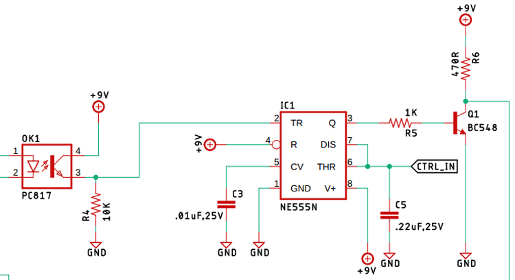
The above image shows the 555 timer control circuit, the 555 is configured in a monostable configuration, so when a trigger signal from the zero-crossing detection circuit hits the trigger, the 555 timer starts to charge the capacitor with the help of a resistor (in general), but our circuit has a MOSFET in place of a resistor, and by controlling the gate of the MOSFET, we control the current going to the capacitor, that's why we control the charging time hence we control the output of the 555 timers.
TRIAC and the TRIAC-Driver Circuit:
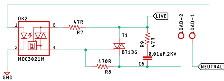
The TRIAC is acting as the main switch which actually turns on and off thus controls the output of the AC signal. Driving the TRIAC using the MOC3021 Opto-Triac-drive, it doesn't only drive the TRIAC, but it also provides optical isolation, the 0.01uF 2KV high voltage capacitor, and the 47R resistor forms a snubber circuit, which protects our circuit from high voltage spikes which occur when it's connected to an inductive load, The non-sinusoidal nature of the switched AC signal is responsible for the spikes. Also, it is responsible for power factor issues, but that is a topic for another article.
Lowpass-Filter and P-Channel MOSFET (Acting as the Resistor in the Circuit):
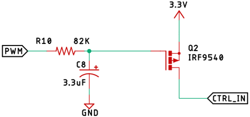
The 82K resistor and the 3.3uF capacitor forms the low pass filter which is responsible for smoothing out the high-frequency PWM signal generated by the Arduino. As previously mentioned, the P-Channel MOSFET acts as the variable resistor, which controls the charging time of the capacitor. Controlling it is the PWM signal which is smoothed out by the low-pass filter.
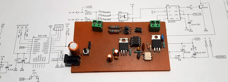
PCB Design for the IoT Controlled Ceiling Fan Regulator
The PCB for our IoT Ceiling Fan Regulator circuit is designed in a single-sided board. I have used Eagle PCB design software to design my PCB but you can use any design software of your choice. The 2D image of my board design is shown below.
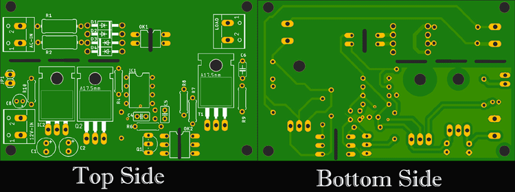
Sufficient ground filling is used to make proper ground connections among all the components. The 3.3V DC input and the 220 Volt AC input is populated at the left-hand side, the output is located on the right-hand side of the PCB. The complete design file for Eagle along with the Gerber can be downloaded from the link below.
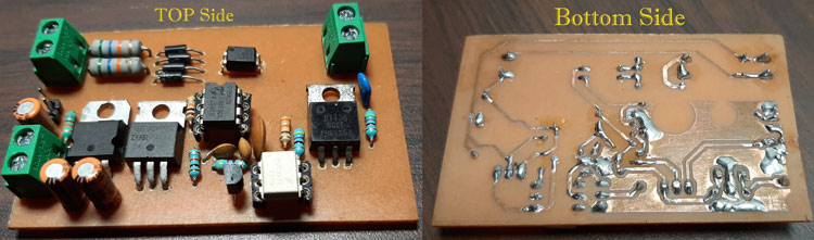
Handmade PCB:
For convenience, I made my handmade version of the PCB and it's shown below.
With this, our hardware is ready as per our circuit diagram, now we have to get our android application and Google firebase ready.
Setting Up A Firebase Account
For the next step, we need to set up a firebase account. All the communication will go through the firebase account. To set up a firebase account, go to the Firebase website and click on 'get started'.

Once you click, you need to log in with your Google account, and

once you are logged in, you need to create a project by clicking on the create a project button.

Doing so will redirect you to a page that looks like the image above. Type the name of your project and click continue.

Again, click continue.

Once you do, you need to agree to some terms and conditions by clicking on the checkbox, next, you need to click on the create project button.

If you have done everything correctly, after some time, you will get a message like this. Once finished, your firebase console should look like the image below.

Now we need to collect two things from here. To do that, you need to click on the name of the project that you have just created. For me, it is CelingFanRegulator, once you click on it, you will get a dashboard similar to the image below.
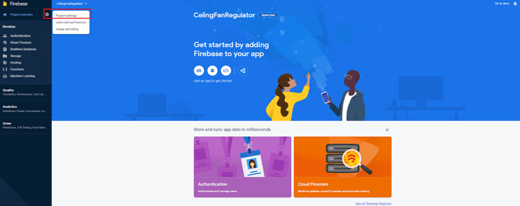
Click on settings, then project settings, the page you will get will look like the images below.
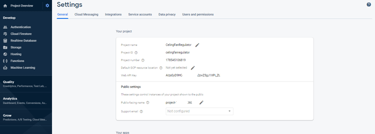
Click on service account -> database secret.
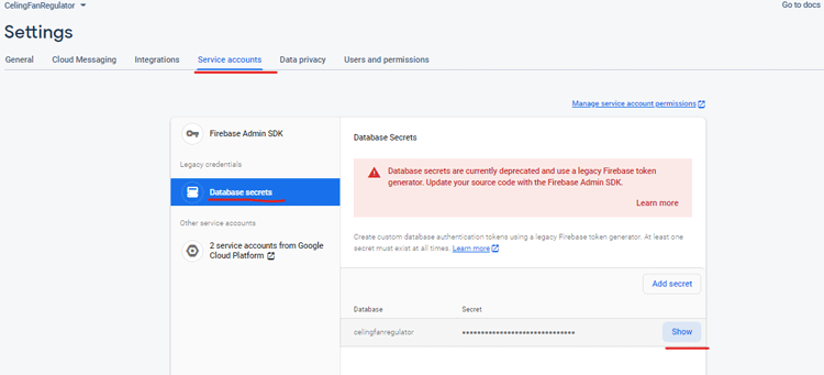
Copy the database secret and keep it someplace for later use.
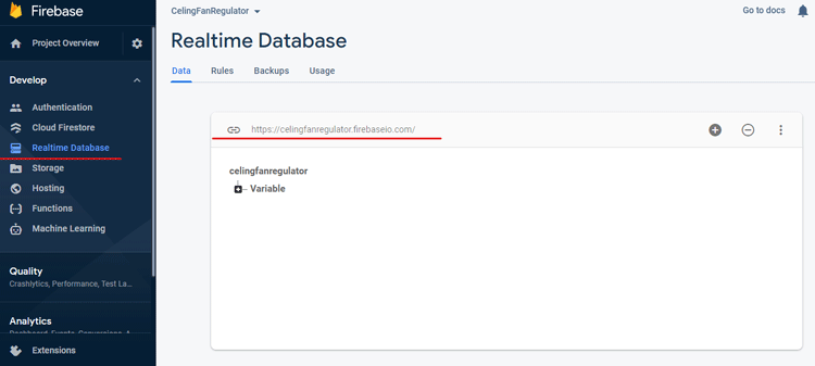
Next, click on the real-time database and copy the URL. also keep that for later use.
And that's all, there is to the firebase side of things.
Arduino Code to Control Fan Regulator with NodeMCU
A simple Arduino code takes care of the communication between firebase and the ESP-12E module, the circuit and code explanation is given below, First, we define all the necessary libraries required, you can download the following libraries from the given links Arduino JSON library and FirebaseArduino library
#include <ESP8266WiFi.h>
#include <FirebaseArduino.h>
#include <ArduinoJson.h>
#include <ESP8266HTTPClient.h>
We will be using the FirebaseArduino library to establish communication with firebase.
// Set these to run examples.
#define FIREBASE_HOST "celingfanregulator.firebaseio.com"
#define FIREBASE_AUTH "1qAnDEuPmdy4ef3d9QLEGtYcA1cOehKmpmzxUtLr"
#define WIFI_SSID "your SSID"
#define WIFI_PASSWORD "your pass"
Next, we have defined the firebase host, firebase auth, which we had earlier saved when we were making the firebase account. Then we have defined the SSID and password of our router.
String Resivedata ;
#define PWM_PIN 14;
Next, we have defined a string type variable, Resivedata where all the data will be stored and we also defined the PWM_PIN where we will get the PWM output.
Next, in the void setup() section, we do the necessary,
  Serial.begin(9600);
  pinMode(PWM_PIN, OUTPUT);
  WiFi.begin(WIFI_SSID, WIFI_PASSWORD);
  Serial.print("connecting");
  while (WiFi.status() != WL_CONNECTED)
  {
    Serial.print(".");
    delay(500);
  }
  Serial.println();
  Serial.print("connected: ");
  Serial.println(WiFi.localIP());
  Firebase.begin(FIREBASE_HOST, FIREBASE_AUTH);
  Firebase.setString("Variable/Value", "FirstTestStrig");
First, we enable the serial by calling the Serial.begin() function. Next, we have set the PWM pin as OUTPUT. We begin the Wi-Fi connection with the help of the WiFi.begin() function and we pass the SSID and Password in the function. We check the connection status in a while loop and once connected, we break the loop and continue on. Next, we print the connected message with the IP address.
Finally, we begin the communication with the firebase with Firebase.begin() function and we pass the FIREBASE_HOST and FIREBASE_AUTH parameters which we have defined earlier. And we set the string with the setString() function, which marks the end of the setup function. In the void loop() section,
 Resivedata = Firebase.getString("Variable/Value");
 Serial.println(Resivedata);
 analogWrite(PWM_PIN, map(Resivedata.toInt(), 0, 80, 80, 0));
 Serial.println(Resivedata);
 delay(100);
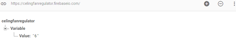
We call the getString() function with Variable/Value where the data is stored in the firebase, an example would be like the image below-
Then we print the value just for debugging. Next, we use the map function to map the value, 80 is used because within the range of 0 - 80, we are able to control the gate of the MOSFET accurately, and the RC lowpass filter is somewhat responsible for this value. Within this range, the phase angle control circuit operates accurately, you may call the value as a hardware-software sweet spot. If you are doing this project and face issues, you need to play with the value and determine the results yourself.
And after that, we use the analogWrite() function to feed the data and enable the PWM, after that, we use the Serial.println() function again just to review the result, and finally, we use a delay function to reduce the hit-count to the firebase API which makes the end of our program.
Building the Fan Regulator App With MIT App Inventor
With the help of AppInventor, we are going to make an android app that will communicate with the firebase and has the authority to change the data which is stored in the firebase database.
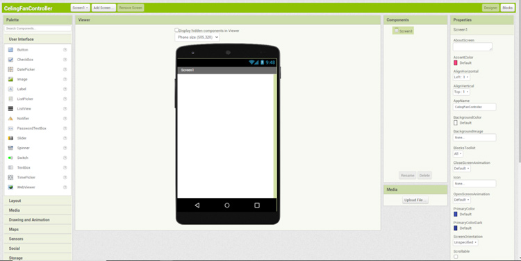
To do that, go to the appInventors website, log in with your Google account, and accept the terms and conditions. Once you do, you will be presented with a screen that looks like the image below.
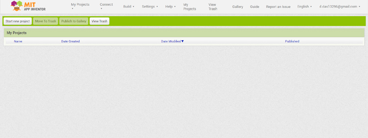
Click on the start a new project icon and give it a name and hit OK, once you do, you will be presented with a screen like the below image.
Once there you need to first put two labels, where this is to put the slider a little bit down, next you need to pull in some modules and they are the FirebaseDB module and the web-module.
The firebaseDB module communicates with the firebase, the web module is used to handle the Http request. Which looks like the image below.
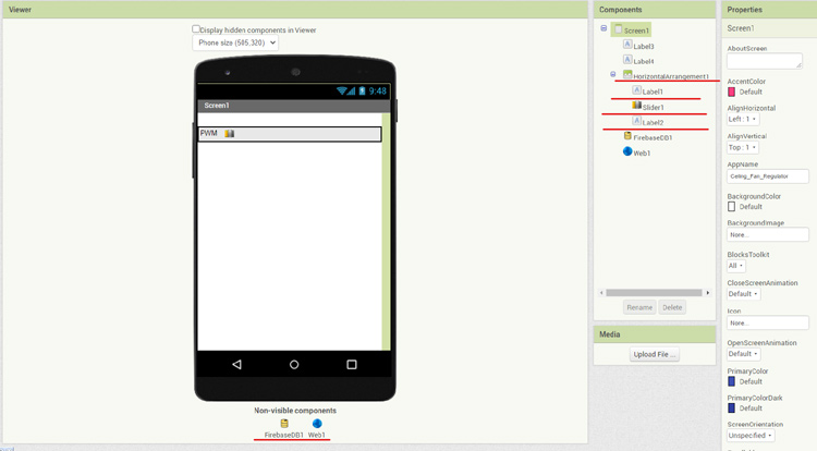
Once that is done, you need to pull in the slider and a label which we named PWM, if you are getting confused at this moment, you can check out some other tutorials regarding making an app with an app inventor.
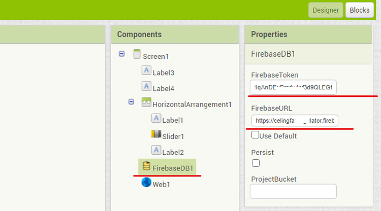
After we are done with the process, click on the firebase DB icon and put in the firebase token and the firebase URL which we have saved while making the firebase account.
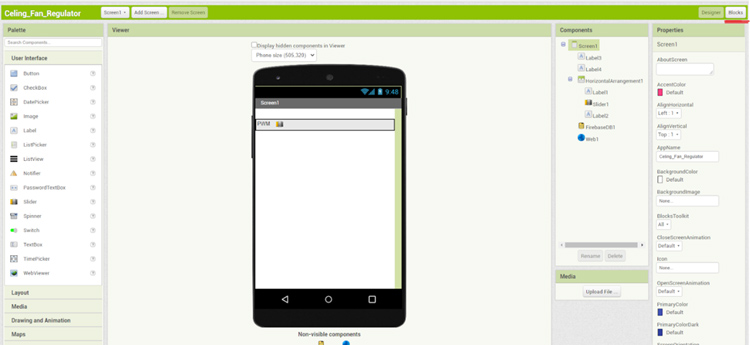
Now, we are done with the design section and we need to set up the block section. To do that, we need to click the block button in the upper right corner beside the designer.
Once click on the slider and you will be presented with a long list of modules, pull out the first module, and hover your mouse over the thumb-position button, you will be greeted with two more modules, pull both of them out. We are going to use those later.
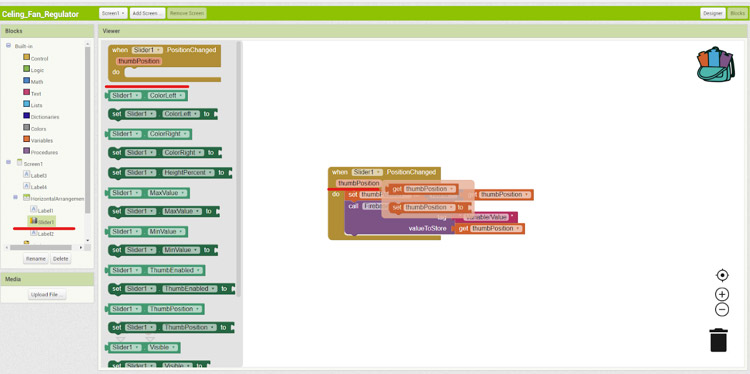
Now we attach the thumbposition variable, we round it off and we get the thumb position value. Next, we click on the firebasedb and pull out the call FirebaseDB.storeValue tag value to store, module and attach it to the bottom of the thumb position value.
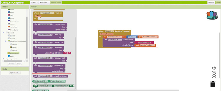
Once done, we pull out an empty textbox by clicking the text block and attach it with the tag, this is the tag which we have set in the Arduino IDE to read and write the data on firebase. Now attach the thumb value variable to the value to store tag. If you have done everything correctly, by moving the slider, you will be able to alter the values in the firebaseDB.
- The .aia(saved file) and .apk (compiled file)
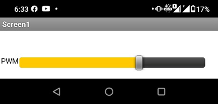
Which marks the end of our app making process. A snapshot of the android application that we just created shown below.
Testing the ESP32 Based Touch Sensor Circuit
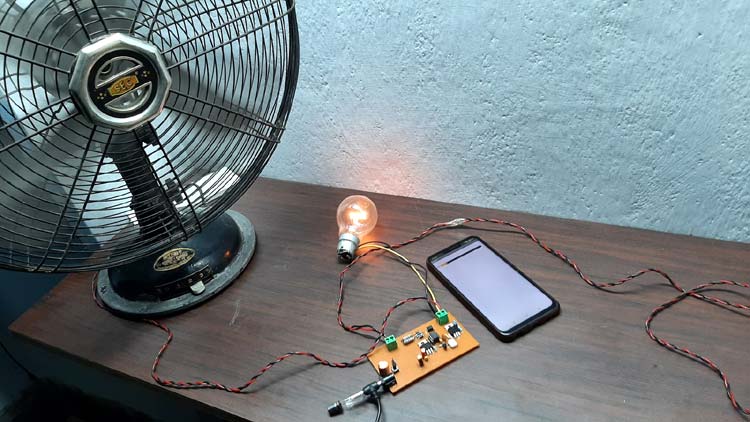
To test the circuit, I have connected an incandescent light bulb parallel to the ceiling fan, and I have powered the circuit with a 5V DC adapter, as you can see in the above picture, the app slider is set to low, that is why the bulb is glowing at low brightness. And the fan is also rotating slowly.
Further Enhancements
For this demonstration, the circuit is made on a handmade PCB but the circuit can be easily built on a good quality PCB, in my experiments, the size of the PCB is really bit due to the component size, but in a production environment, it can be reduced by using cheap SMD components, I found using a 7555 timer instead of a 555 timer increase the control extensively, furthermore, the stability of the circuit increases as well.
Complete Project Code
// Code for IoT Based AC Fan Speed Control using NodeMCU

#include <ESP8266WiFi.h>
#include <ESP8266HTTPClient.h>
#include <FirebaseArduino.h>
#include <ArduinoJson.h>
// Set these to run examples.
#define FIREBASE_HOST "celingfanregulator.firebaseio.com"
#define FIREBASE_AUTH "1qAnDEuPmdy4ef3d9QLEGtYcA1cOehKmpmzxUtLr"
#define WIFI_SSID "deba_2.4"
#define WIFI_PASSWORD "il2ww*ee"
String Resivedata ;
#define PWM_PIN 14
void setup()
{
  // Debug console
  Serial.begin(9600);
  pinMode(PWM_PIN, OUTPUT);
  WiFi.begin(WIFI_SSID, WIFI_PASSWORD);
  Serial.print("connecting");
  while (WiFi.status() != WL_CONNECTED)
  {
    Serial.print(".");
    delay(500);
  }
  Serial.println();
  Serial.print("connected: ");
  Serial.println(WiFi.localIP());
  Firebase.begin(FIREBASE_HOST, FIREBASE_AUTH); // used to enable communication
  Firebase.setString("Variable/Value", "FirstTestStrig"); //set the variables
}
void loop()
{
  Resivedata = Firebase.getString("Variable/Value");//get the variables
  Serial.println(Resivedata); //debug Resivedata
  analogWrite(PWM_PIN, map(Resivedata.toInt(), 0, 80, 80, 0)); // map and analogwrite function.
  Serial.println(Resivedata);//debug Resivedata again.
  delay(100);// delay of 100ms to reduce the hitcount.
}
Thank you very much. This article helps me to learn Firebase and MIT app inventor too.