 Vedhathiri
Author

LEDs are commonly used in electronic circuits, and with the LEDs, you can make many things which are interesting. You’ve probably seen many types of decorative lighting patterns-running lights, festival chasers, or rhythmic blinking effects that instantly stand out. This LED chaser circuit recreates that eye-catching style using a simple combination of the 555 timer IC and the CD4017 counter IC. An LED chaser circuit using 555 timer IC creates captivating running light effects perfect for decorative displays and electronics projects. With just a handful of components, this LED chaser circuit using 4017 and 555 lets you create smooth, dynamic lighting effects that are perfect for DIY projects, home decor, or electronics learning. Whether you're building a simple LED chaser circuit for learning or creating an LED chaser light for decoration, this guide covers everything from the 555 timer IC pin diagram to complete circuit assembly. You can also check out our Circular LED Chaser for more inspiration.
Table of Contents
- What does an LED Chaser Circuit mean?
- Components Required
- 555 Timer IC Configuration
- └ 555 Timer IC Pinout Explained
- CD4017 IC Pinout and Functionality
- └ CD4017 Pin Configuration Details
- Circuit Diagram
- Circuit Board Assembly
- └ Step-by-Step Assembly Instructions
- How the LED Chaser Circuit Works
- Real-Time Working Demonstration
- Troubleshooting
- Enhancements and Modifications
What Does an LED Chaser Circuit Mean?
The LED Chaser Circuit is an electronic formation composed of LEDs that will fire or blink in sequence, creating a running or chasing effect with the lights. The LED chaser circuit using 555 timer IC and the CD4017 decade counter within the LED Chaser Circuit provides accurate timing and sequential output for decorative lighting, electronic displays, and an approach to teaching basic concepts of digital electronics.
Components Required for the LED Chaser Circuit
The LED chaser circuit board requires minimal components, making it an excellent beginner project. The components listed below are the ones used to build the LED Chaser Circuit.
| Components | Quantity |
| 1K Ohms Resistor | 1 |
| 50K Ohms Variable Resistor | 1 |
| NE555 IC | 1 |
| CD4017 IC | 1 |
| Blue LED | 10 |
| 0.1uf (104) Ceramic Capacitor | 1 |
| 10uF Capacitor | 1 |
| Power Supply | 9v |
555 Timer IC Pin Diagram and Configuration
Understanding the 555 timer IC pin diagram is crucial for building your LED chaser circuit. Let's discuss the pinout of the 555 timer, which is used in this LED chaser.
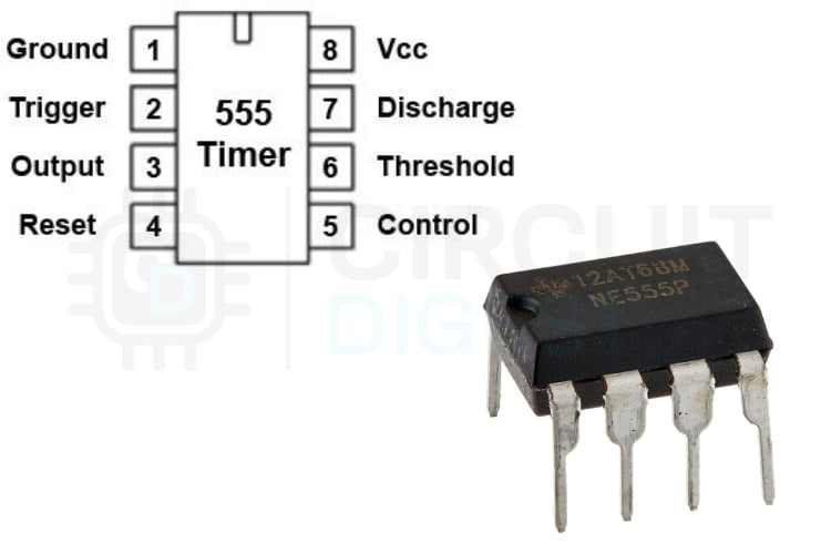
555 Timer IC Pinout Explained
Pin 1 - Ground:
Connects to the circuit ground and acts as the reference point for the IC.
Pin 2 - Trigger:
A low pulse on this pin (below 1/3 of VCC) sets the internal flip-flop and makes the output go HIGH.
Pin 3 - Output:
Provides the output signal. It can source or sink current and drive loads up to about 200mA.
Pin 4 - Reset:
Active-LOW reset input. Pulling it LOW forces the output LOW. Usually tied to VCC to avoid accidental resets.
Pin 5 - Control Voltage:
Allows external control of the threshold level. Normally connected to ground through a 0.01µF capacitor to reduce noise.
Pin 6 - Threshold:
When the voltage on this pin reaches 2/3 of VCC, it resets the flip-flop, and the output goes LOW.
Pin 7 - Discharge:
Connected to an internal transistor. When the output is LOW, this pin is pulled to ground and discharges the timing capacitor.
Pin 8 - VCC:
Power supply pin. Connects to a positive voltage (typically 3.6V to 15V).
CD4017 IC Pinout and Functionality
The CD4017 decade counter is the heart of sequential control in this LED chaser circuit using 4017 and 555.
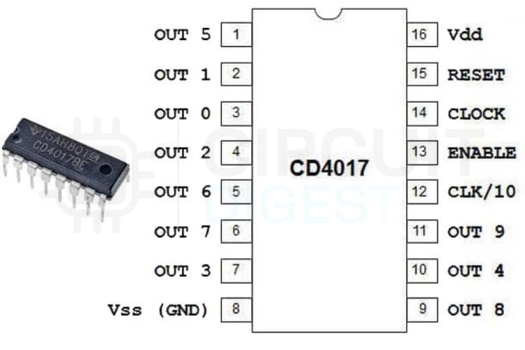
CD4017 Pin Configuration Details
Pin 1-7, 9-11 - Outputs (Q0-Q9):
These are the ten decoded outputs of the counter. Only one output goes HIGH at a time, advancing with each clock pulse.
Pin 8-Ground:
Connected to the circuit ground.
Pin 12-Carry Out (CO):
Goes HIGH after every 10 clock pulses. Useful for cascading multiple CD4017 ICs.
Pin 13-Clock Enable (CE):
Active-HIGH pin. When HIGH, the IC ignores clock pulses. When LOW, counting works normally. Often tied to the ground.
Pin 14-Clock Input:
Receives the clock signal. Each rising edge of the clock moves the counter to the next output.
Pin 15-Reset:
Active-HIGH reset input. When taken HIGH, the counter jumps back to Q0. Usually connected to ground during normal operation.
Pin 16-VCC:
Power supply pin. Works between 3V and 15V, depending on the version.
LED Chaser Circuit Diagram
This LED chaser circuit diagram shows the complete schematic for building your LED chaser light. This is how the components are assembled to make the circuit of the LED chaser.

This image shows a circuit simulation of a 555 timer connected to a CD4017 decade counter on a breadboard. A 9V battery powers the setup, and the LEDs are arranged in a step pattern to create a running light effect. The potentiometer adjusts the speed of the LED sequence.
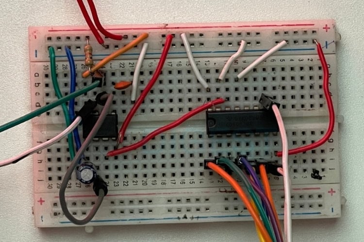
LED Chaser Circuit Board Assembly
Building your LED chaser circuit board requires careful component placement. This real-time setup demonstrates proper breadboard assembly for the simple LED chaser circuit. The setup below shows how the components are assembled in real-time.
Step-by-Step Assembly Instructions
Test the LED chaser circuit using 555 timer IC before building it physically using this TinkerCAD simulation:
https://www.tinkercad.com/things/20r5BxmLEB3-led-chaser
This online simulation shows the circuit uses a 555 timer to generate pulses and a CD4017 counter to drive the LEDs in sequence, creating a chaser effect.
The potentiometer changes the RC time constant of the 555 timer.
Higher resistance → slower pulses → slower LED chasing.
Lower resistance → faster pulses → faster LED chasing.
→ Step 1: Connect the Positive (Red) 9V Battery to Power and the negative (Blue) 9V Battery to Ground
→ Step 2: Insert the 555 Timer IC, placing Pin #1 next to the Ground Rail and Pin #8 next to the Power Rail
→ Step 3: Have all timing components fully installed. A 1K Ohm Resistor, 50K Potentiometer, and 10uF Capacitor are all necessary as shown in the schematic.
→ Step 4: Install the CD4017 IC properly and connect Pin #14, which is the only output of the 555 timer (Pin #3).
→ Step 6: Build your LED Array. You need a total of 10 LEDs, 220 Ohm Current Limiting Resistors for each LED, connected to all outputs of the CD4017.
→ Step 7: Insert Decoupling Capacitors into the VCC and GND, between both ICs, using 0.1uF capacitors.
→ Step 8: Before applying power to the final product, double-check that all connections are correct.
How the LED Chaser Circuit Works
The LED chaser circuit using 4017 and 555 operates through synchronised timing and sequential control:
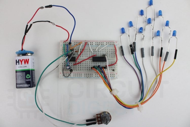
This image shows a complete breadboard setup powered by a 9V battery, where a 555 timer is used to generate clock pulses for a CD4017 counter IC. The wiring connects the IC outputs to a series of LEDs arranged on the right side to create a running-light pattern. A potentiometer is included to adjust the timing speed, and the entire layout clearly demonstrates how the 555 and CD4017 work together in a simple LED chaser circuit. Increasing resistance slows the RC time constant, producing slower pulses and a gradual LED chaser light effect.
In this LED chaser circuit, a 555 timer is used as a pulse generator, producing a steady stream of on-off signals at a fixed speed. These pulses are sent to the clock input of the CD4017, a decade counter that moves its output from one pin to the next each time a pulse arrives. Each output pin is connected to an individual LED through a resistor, so every incoming pulse makes the next LED glow while the previous one turns off, resulting in a clean chasing or running-light effect. After the last LED in the sequence turns on, the counter returns to the first output and the pattern repeats continuously. The Reset and Clock Enable pins are kept at fixed levels so the counting proceeds smoothly without interruption, and both ICs share the same power and ground to keep the circuit stable. Do check out our Building a LED Dimmer Circuit using 555 Timer IC and BC557 Transistor, which will give you a clear idea about the 555 Timer IC and BC557 Transistor.
Real-Time Working Demonstration of the LED Chaser Circuit
Watch the LED chaser light pattern in action.
This shows the change in the LED pattern. If the potentiometer is adjusted, the LED will start to speed up or slow down; these changes cause the LED to blink in a pattern.
Speed Control Mechanism
The 50kΩ potentiometer within the [155]555 Timer circuit determines the speed of the chasing LEDs via:
- Maximum Resistance (50kΩ) provides a slow, smooth movement of LEDs at approximately 0.7 Hz.
- Mid-point Resistance (25kΩ) produces a moderate chasing speed of around 1.4 Hz.
- Minimum Resistance (1kΩ) produces a very fast-paced pattern of LED operation of about 7 Hz.
Troubleshooting the LED Chaser Circuit
Enhancements and Modifications
1. More LED Count (20 LEDs)
To get 20 outputs in sequence, 2 CD4017s can be cascaded by connecting Pin 12 (Caraout) of the first to Pin 14 (Clock) of the second.
2. To have a bidirectional chase pattern
To make a chase pattern that reverses, create a CD4029 up/down counter to control a reverse clock signal, or use a 2nd CD4017 and connect alternate LED connections to change their glow direction.
3. A Multi-Colour LED Chase
You can replace the standard red LEDs with RGB LEDs. And by adding three additional CD4017 ICs (P151, P122, and P133) for each primary colour, you're now able to control your colours separately with the three channels you'll create.
4. Sound-Responsive LED Chaser
Instead of a 555 timer circuit, you can add a microphone preamp with a comparator circuit that will let you have lighting effects synced to your music!
Frequently Asked Questions
⇥ 1. Why does only one LED glow at a time?
Only one LED lights up at a time because the CD4017 IC sends a high signal to one output pin at a time.
With each clock pulse, the high signal moves to the next pin, turning on the next LED in a sequence and creating the chasing effect.
⇥ 2. What is an LED chaser circuit?
An LED chaser circuit is a setup where LEDs light up one after another in a sequence, making a running light effect. This kind of setup is often used in decorative lighting and display applications.
⇥ 3. What components are mainly used in this circuit?
This project uses two main integrated circuits (ICs):
- 555 Timer IC-It is used to generate continuous clock pulses.
- CD4017 Decade Counter IC-It controls the sequence of LEDs by activating them one after another based on the clock pulses.
⇥ 4. How does the 555 Timer work in this project?
The 555 Timer is set up in astable mode, which means it continuously creates pulses. These pulses are sent to the CD4017’s clock input and determine how fast the LEDs turn on and off.
⇥ 5. What does the CD4017 IC do?
The CD4017 is a 10-stage counter IC. Every time a pulse is received, it moves the high signal to the next output pin, starting from Q0 to Q1, then Q2, and so on up to Q9. This causes the LEDs connected to these pins to light up one after another.
⇥ 6. How can I change the speed of the LED chasing pattern?
You can adjust the speed by changing the resistance of the potentiometer connected to the 555 Timer. A higher resistance results in slower pulses, making the LEDs move more slowly. A lower resistance results in faster pulses, making the LEDs chase each other more quickly.
⇥ 7. What power supply is required for this circuit?
This circuit can be powered by a 9V battery or a DC supply that provides 5 to 12 volts. Both the 555 Timer and the CD4017 IC operate within this voltage range.
This tutorial was created by the CircuitDigest engineering team. Our experts focus on creating practical, hands-on tutorials that help makers and engineers master Raspberry Pi projects, Electronic Circuit projects and IoT development projects.
I hope you liked this article and learned something new from it. If you have any doubts, you can ask in the comments below or use our Circuit Digest forum for a detailed discussion.
LED-Based Electronics Projects
Below are a few projects that highlight basic electronics concepts through LED patterns and control logic.

LED Chaser using Arduino and Rotary Encoder
In this project, we are going to interface a ROTARY ENCODER with ARDUINO. A ROTARY ENCODER is used to know the position of movement and the angular movement of a motor or axis. It’s a three-terminal device, usually, with power and ground pins; there are a total of 5 terminals.

Here we are going to use a 10-bit DECADE counter. The counter chip is CD4017BE. With a 10-bit DECADE counter, we can count events up to 10. So it would take 11 clock pulses for the chip to reset itself to zero.

LED Roulette Circuit using 555 timer IC
Here we are going to show you how to make an LED Roulette Circuit using a 555 timer IC. Roulette is a casino game named after the French word, which means little wheel.
