

In this project we are going to interface a ROTARY ENCODER with ARDUINO. ARDUINO UNO is an ATMEGA controller based development board designed for electronic engineers and hobbyists. In ARDUINO we have 20 I/O pins, so we can program 20 pins of UNO to be used as either input or output.
A ROTARY ENCODER is used to know the position of movement and angular movement of a motor or axis. It’s a three terminal device usually, with power and ground pins there are total 5 terminals. A ROTARY ENCODER module is shown below.
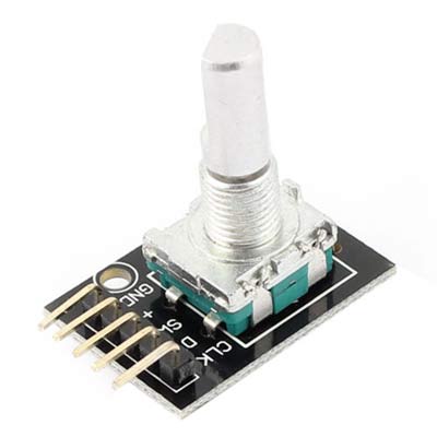
The pins of a rotary encoder are:
- Ground
- Positive connected to +5V
- Output signal A pin
- Output signal B pin
- Clock pin or common pin
The ENCODER provides pulses representing the change in the shaft position for the systems to understand. Consider a ROTARY ENCODER is powered up and the shaft is moved.
As shown in above table, consider the shaft is moved clock wise. With this there will be Falling Edge at the A terminal then at B terminal.
Consider the shaft is moved Anti clock wise. With this there will be Falling Edge at the B terminal then at A terminal.
This edge will occur once for 360/20 = 18 degrees (This is for a Encoder with 20 position, this changes from type to type, higher the count greater the accuracy).
With both above conditions, we can get direction and degree of rotation. Thus we get required parameters for getting the position of a shaft.
Components Required
Hardware: Arduino uno board, connecting pins, 220Ω resistor, LED (eight pieces), 1KΩ resistor, 220Ω resistor (2pieces), 100nF capacitor (2 pieces ), bread board.
Software: Arduino nightly
Circuit Diagram and Working Explanation

The capacitors here are for neutralizing the contact bouncing effect in ENCODER. Without those capacitors there will be some serious problems in position reading.
When the shaft is moved there will be time difference between two output pins output. The Arduino UNO will recognize this time difference for clockwise of Anti clock wise rotation.
If the rotation is clockwise the binary count is incremented by one, and this count is shown in LED port as shown in figure.
If the rotation is Anti clock wise the binary count is decremented by one and the binary count is shown at LED byte.
Working of Arduino with Rotary Encoder is explained step by step in C code given below.
Complete Project Code
int count =0;
int x=0;
int y=0;
void setup()
{
                DDRD = 0xFF;//LED port as output
                PORTD =0;//0V at PORTD

                pinMode(8,INPUT);// sets the pin8 as input
                pinMode(9,INPUT);// sets the pin9 as input
}

void loop()
{
    if ((digitalRead(8)==LOW)||(digitalRead(9)==LOW))//If any Encoder pins show falling edge execute lop
                {
                                delay(10);
                                if (digitalRead(8)==LOW)//if PINB is second to go LOW
                                {
                                                if (count<255)
                                                {
                                                                count++;//increment binary count if count is less than 255
                                                }
                                }
                                if (digitalRead(9)==LOW)//is PINA is second to go LOW
                                {
                                                if (count>0)
                                                {
                                                                count--;//if binary count is greater than 0 decrease count by 1
                                                }
                                }
                                delay(100);
                                while ((digitalRead(8)==LOW)&&(digitalRead(9)==LOW))// wait till shaft position reset
                                {
                                }
                }

                PORTD = count;//showing count at LED port.
}
