

Have you ever wanted to add some cool lighting effects to your electronic circuits or spice up your home decor with a mesmerizing light show? Well, a circular LED chaser might just be what you're looking for! And the good news is that it's easy to build one using the 74HC595 integrated circuit. So in this article, we will show you how to build a stunning circular LED chase. So, if you're ready to bring some life to your electronic projects and impress your friends with some DIY lighting wizardry, keep reading to learn more about the 74HC595 circular LED chaser!
74HC595 8-Bit Shift Register Pinout
The 74HC595 is an 8-bit serial-in, parallel-out shift register IC that is commonly used to drive leds motor or any other electronic equipment.
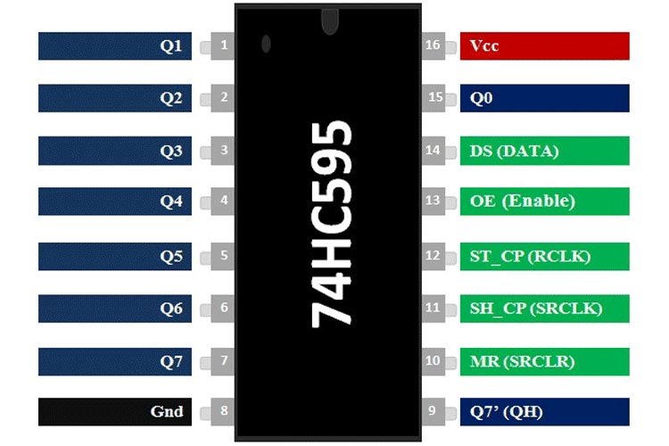
PIN(Q0 - Q7) Output pin of the IC, that can be controlled serially.
GND Connected to the Ground of the Circuit.
MR Master Reset: Resets all outputs as low. Must be held high for normal operation
SH_CP Clock: This is the clock pin to which the clock signal has to be provided from MCU/MPU.
ST_CP The Latch pin is used to update the data to the output pins. It is active high
OE Output Enable: The Output Enable is used to turn off the outputs. Must be held low for normal operation
DS Serial Data: This is the pin to which data is sent, based on which the 8 outputs are controlled
VCC This pin powers the IC, typically +5V is used.
Components Required to Build Circular LED Chaser
Components required to build the 74HC595 based Circular LED Chaser are simple and can be found in your local hobby store
- IC 74HC595 *- bit Shift Register
- NE555 Timer IC
- 10K Resistor
- 1M Resistor
- BC548 NPN Transistor
- Copper Wire
- LED 32 Piece Green
- 4.7uF capacitor
- 10K trim pot
Circuit Diagram - 74HC595 based Circular LED Chaser

The working of the circuit is very simple, when the circuit is powered on the 555 timer generates a clock signal that is fed to the Cp pin of the shift register. The 10K potentiometer is the frequency of the clock signal so that you can speed up or slow down the animation on the circuit. Each time the clock signal rises the clock signal shift register outputs the data on its input (DS) to the first output (Q0) and shifts the data to the next output (Q1). This process continues until the data reaches the last output (Q7), at which point it is shifted back to the first output (Q0). and the whole process continues.
Projects using 74HC595 IC and LEDs

If you are looking for some cool, interesting and funkey project online which will make you stand out in a party then this project is for you, because in this project we have built DIY RGB LED glasses which can also display visual effects.
If you love spectrum analyzers like me then this project is for you because in this project we have made a DIY! Music spectrum analyzer with ARM microcontroller and Keil IDE.

Looking for a cool little night lamp on the internet, then this project is for you, because in this project we have made a cool little Android operated night lamp with Blunk app and ESP8266 microcontroller.

If you are looking for a cool little LED project then this project is for you, because in this project we have made a simple LED christmas tree using RGB leds and some basic components.
Comments
Correction:
LEDs directly in ***parallel*** is poor design practice.

1. The basic design approach of having multiple LEDs directly in series without ballast resistors is an extremely bad design practice. It assumes that all LEDs are perfectly matched in their Vf curve and efficacy. The LEDs will not be the same brightness.
2. There are no current-limiting resistors for the LEDs, so the circuit hopes that the IC does not burn up. Again, extremely bad design practice.
3. The schematic drawing is sloppy and undisciplined, with ground symbols pointed in three different directions and unnecessary crossed nets. It is confusing and difficult to read. This looks like the work of an untrained child.
4. There is a critical error in the schematic. It will not work as shown.
ak