
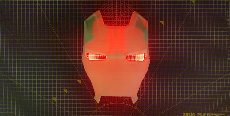
Avengers Assemble! Who does not like the Marvel Cinematic Universe? So, today we have a great project for you people that is a Wi-Fi-controlled Ironman mask. These days evolution and adaptation of 3D printed tools have seen a great increment for a plethora of purposes. We brought the use of a cool 3D printed design to make it into an Ironman mask that can be controlled over the Internet. The project includes basic components and can perform multiple functions such as a color switch, simple ON/OFF, timer control, and a brightness equalizer for the LEDs using the Blynk application.
As we all know how popular 3D printed techniques are these days, just getting those techniques into. Although 3D printers can be used to design some really helpful stuff, we can also use them in order to improve the aesthetics and make some nifty products. Using basic circuits and implementing the circuits over Perfboards to make Ironman lights glow. The project that we build today could be used as a collectible showcase item for your home or workplace. So get ready and let's begin!
Components Required for Wireless Ironman Faceplate Wall Light
- ESP 8266-01
- Neopixel LED strips
- 7.4V 2200mAh Li-Ion battery
- LD1117V33 (LD33V) 3.3V Voltage Regulator
- 10uF 63V Capacitor
- 7805 Voltage regulator
- DC Barrel jack connectors
Introduction to Major Components
- Neopixel LED: Neopixel is widely used for a wide variety of projects. It is an RGB LED light with a built-in driver IC that makes these lights addressable and programmable. The Neopixel LED strip has three pins to drive several RGB NeoPixel LEDs. Two of those pins are for power and ground, whereas the third pin is used as Data In (DI). A Neopixel LED requires 5V to function, and it takes up to 60mA current per LED at full brightness. The Data In pin is used to control and address the different LEDs in the strip and is used to control the brightness, color, etc. of the LED.
- ESP 8266-01: ESP8266-01 is a Wi-Fi Transceiver Module. It is a self-contained SOC with an integrated TCP/IP protocol stack which allows one to give micro-controllers access to Wi-Fi networks.
Circuit Connections
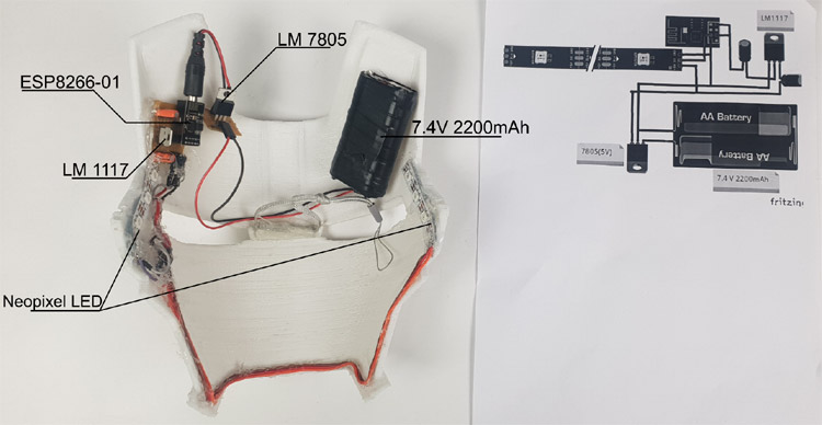
The connections for the setup are not very complex so they can be followed along as per the image shown below. The 7.4V 2200mAh battery is connected to the 7805 IC in order to reduce the voltage levels to 5V for the proper operation of the Neopixel LED. The battery's positive terminal is connected to the input pin of the 7805 and the negative to the ground pin of the IC. Once, the voltage level is dropped, the output is taken from the output and ground pin of the IC. The 5V output is divided into two and one ends is supplied to the Neopixel LED strip whereas the other part is given to the LM1117 IC which further reduces the voltage levels to 3.3V for the proper function of ESP 8266-01. Once this voltage regulation part is completed, now let's have a look at the ESP 8266-01 module connections with the Neopixel LED. Pin 1 of the ESP module is grounded whereas the 2nd pin (GPIO 2) is connected to the DIn pin of the Neopixel LED and the 5V pin of the Neopixel is directly connected to the 5V output rail from the 7805 IC.

Here, you can see my complete setup of the Ironman mask. The wiring has been done along the borders of the mask in order to prevent any shadow from the components or wires. You can place the components in a similar fashion if you wish to.
Interfacing the Blynk App
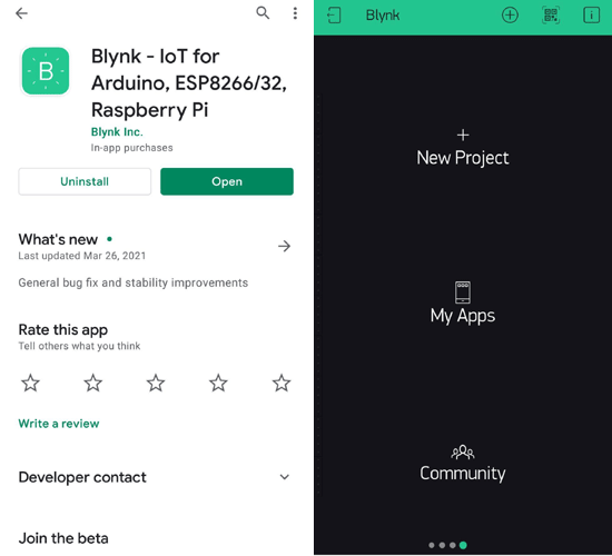
Blynk is an IoT-based platform focused on making IoT simpler for developers like us. Blynk allows us to build graphical interfaces by which we can control or visualize our data just by dragging and dropping different widgets available in the application itself. Using different Blynk libraries you can connect over 400 hardware models to their cloud (the hardware includes; Raspberry Pi, Arduinos, Node MCU, etc.) Blynk app is available both on Android as well as iOS. Any hardware can be connected to the Blynk cloud over the internet with the connectivity available on the hardware such as ESP, Ethernet, Wi-Fi, etc. The images below showcase the setting up of the Blynk app over an Android smartphone.
You can also make your own local server for Blynk over Raspberry Pi. You can follow this project link if you are interested.
Creating a New Project:
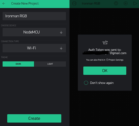
After successful installation, open the application and click on “New Project”. On the next screen, set the parameters like project name, board type, and connection type. For this project, select the device as “ESP8266” and connection type as Wi-Fi and click on “Create”. Follow the steps given in the image below.
Download Blynk APP: Google Play | App Store
Creating the Graphical User Interface (GUI):
Open the project in Blynk, click on the “+” sign where it will show many widgets. In our case, we need an RGB Color Picker which is listed as “zeRGBa”, a button, a slider, and a timer that will be used for different operations of the LED strip.
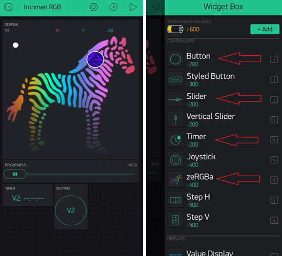
Setting up the Widgets:
- Button: It is a simple yet useful tool used to ON/OFF a device. The Blynk app comes in two modes, push and switch. This widget sends 1(High) on the press and 0(Low) on the release.
- Slider: Slider basically works as a variable resistor(potentiometer) and allows the user to send analog values between the minimum and the maximum range set by the user.
- Timer: A very useful tool which helps to set the time and send High or Low signal even if the smartphone or the app is offline.
- zeRGBa: This widget is an interesting one. zeRGBa is used as an RGB color picker and also the intensity of the color.
Setting up instructions for the Blynk Widgets:
You can follow along with the images attached below and set up the widget settings for your own GUI using the blynk application. The settings for the buttons, zeRGBa, Timer, and slider are given below, where virtual pins (V2, V3) along with the range are defined below.
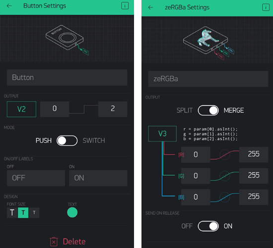
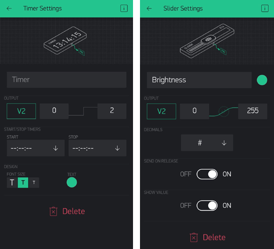
Once you have these settings done in your blynk app, you can press the “play arrow” key on the top right of the screen and use your widgets. You can simply add other widgets available in the blynk library by pressing the “+” sign and further defining the virtual pins and the range to them.
→ How to get the authentication code?
Once you click on ‘CREATE’, you will get the authentication code for the Blynk project on the email Id you have registered with.
To learn more about the Blynk app, follow this link.
Code for Wireless Ironman Faceplate Wall Light
Libraries to be installed before running the code:
FastLED.h library: The FastLED library is for efficiently controlling multiple LED chipsets including Nexopixel, Dotstar, WS2801 by Sparkfun, and more. This library also includes multiple functions of performing 8-bit calculations to manipulate the RGB values and also low-level classes for abstracting out access to SPI hardware and pins and still keeping it very fast.
Download FastLED.h library from this link.
BlynkSimpleEsp8266.h Library:
BlynkSimpleEsp8266.h is a library that needs to run the blynk application over wireless network devices and helps it to communicate with the ESP module
Download BlynkSimpleEsp8266.h library from this link.
Once the libraries are installed, we can begin coding by including all the necessary libraries and defining the input and output pins.
#include <ESP8266WiFi.h> // include ESP8266WiFi.h library
#include <BlynkSimpleEsp8266.h> // include BlynkSimpleEsp8266.h library
#include "FastLED.h" // include Fast.LED.h library
#include <Adafruit_NeoPixel.h> // include Adafruit_NeoPixel.h library
#define BLYNK_PRINT Serial // defines the object that is used for printing over serial monitor
#define PIXEL_PIN    2  // digital IO pin of ESP 8266-01 connected to the LED
#define PIXEL_COUNT 6  // Number of neopixel LED used
#define FASTLED_ESP8266_RAW_PIN_ORDER
#define NUM_LEDS1 60
#define COLOR_ORDER GRB
#define LED_TYPE WS2812
CRGB leds1[NUM_LEDS1];
After including all the libraries and defining the pins and the ports, it is now time to enter the Blynk and Wi-Fi credentials like auth token and the Wi-Fi name and password for the Wi-Fi to which ESP-01 should connect with. The blynk authentication code (char auth[ ]) can be obtained from the email ID you’ve registered with.
char auth[] = "Jdr-------------------------------------cqh"; // authentication code by Blynk
char ssid[] = "A------------2";  // Wireless network name
char pass[] = "b-----------------5";  // Wireless network password
int data=255;
int r,g,b;
void setup()
{
  Serial.begin(9600);
  Blynk.begin(auth, ssid, pass);
  FastLED.addLeds<LED_TYPE, PIXEL_PIN, COLOR_ORDER>(leds1, NUM_LEDS1).setCorrection( TypicalLEDStrip );
}
BLYNK_WRITE() function is used to check the incoming data at the virtual pins V2 and V3. Here virtual pins V2 and V3 are defined in the blynk application to specific widgets to perform functions.
BLYNK_WRITE(V3)
{
  r = param[0].asInt();
  g = param[1].asInt();
  b = param[2].asInt();
  static1(r, g, b,data);
}
Inside the loop() function, Blynk.run() is there to check for the incoming commands from Blynk Graphical user interface (GUI). The incoming string is then saved into a variable and using the ‘if’ condition, the operations are executed accordingly.
void loop()
{
  Blynk.run();
}
BLYNK_WRITE(V2)
{
data = param.asInt();
static1(r, g, b,data);
}
void static1(int r, int g, int b,int brightness)
{
  FastLED.setBrightness(brightness);
  for (int i = 0; i < NUM_LEDS1; i++ )
  {
    leds1[i] = CRGB(r, g, b);
  }
  FastLED.show();
}
Working with the Setup
Once we have placed all the components and uploaded the code to the ESP board, we can now plug in the power supply. Once the setup is on, it should get connected to the mobile or the device with the Blynk application whose wireless network credentials are mentioned in the code. Once you have set up the whole application with the widgets including ON/OFF switch, RGB Spectrum, Brightness equalizer, and the timer. You are now ready to use the functions and customize your Ironman mask wirelessly using IoT.
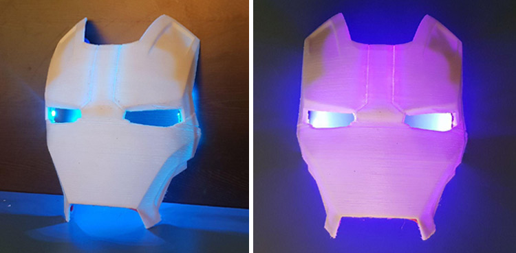
I tested the project, and it worked very well for me. I was able to control the brightness of the Neopixel LEDs, change the colors of the LED, I was able to switch the LEDs ON and OFF, and even set a timer to turn on and off the LED strip inside the Ironman mask faceplate. This custom mask is a very helpful and aesthetic showpiece for the room or workplace. I will hang it on the wall and amaze people with how it works wirelessly. Hope you guys enjoyed this project and learned something new. If you have any questions regarding this project, please put them in the comment box below or post your queries to our forum.
You can also check out another similar project of controlling a WS2812B RGB LED Matrix using Arduino and blink at Circuit digest.
A huge shout out to the designer of this Ironman mask design, if you wish to check it out and make your own 3D printed version, kindly check the Thingiverse link and download the STL files and print your own Ironman faceplate.
Link: https://www.thingiverse.com/thing:3066439
You can watch the whole video of the project for a better understanding.
Complete Project Code
#include <ESP8266WiFi.h> // include ESP8266WiFi.h library

#include <BlynkSimpleEsp8266.h> // include BlynkSimpleEsp8266.h library

#include "FastLED.h" // include Fast.LED.h library

#include <Adafruit_NeoPixel.h> // include Adafruit_NeoPixel.h library

#define BLYNK_PRINT Serial // defines the object that is used for printing over serial monitor

#define PIXEL_PIN    2  // digital IO pin of ESP 8266-01 connected to the LED

#define PIXEL_COUNT 6  // Number of neopixel LED used

#define FASTLED_ESP8266_RAW_PIN_ORDER

#define NUM_LEDS1 60

#define COLOR_ORDER GRB

#define LED_TYPE    WS2812

CRGB leds1[NUM_LEDS1];

char auth[] = "Jdr-------------------------------------cqh"; // authentication code by Blynk

char ssid[] = "A------------2";  // Wireless network name

char pass[] = "b-----------------5";  // Wireless network password

int data=255;

int r,g,b;

void setup()

{

  Serial.begin(9600);

  Blynk.begin(auth, ssid, pass);

  FastLED.addLeds<LED_TYPE, PIXEL_PIN, COLOR_ORDER>(leds1, NUM_LEDS1).setCorrection( TypicalLEDStrip );

}

BLYNK_WRITE(V3)

{

  r = param[0].asInt();

  g = param[1].asInt();

  b = param[2].asInt();

  static1(r, g, b,data);

}

void loop()

{

  Blynk.run();

}

BLYNK_WRITE(V2)

{

data = param.asInt();

static1(r, g, b,data);

}

void static1(int r, int g, int b,int brightness)

{

  FastLED.setBrightness(brightness);

  for (int i = 0; i < NUM_LEDS1; i++ )

  {

    leds1[i] = CRGB(r, g, b);

  }

  FastLED.show();

}

The old version of BLYNK has expired