
In last tutorial, we explained controlling a Robot using Wi-Fi and Arduino, and in this article we are with our next IOT Based Project- RGB LED Flasher using Wi-Fi. Here we have used Arduino and ESP8266 Wi-Fi Module to control the colors of RGB LED, through a Android Phone, over the Wi-Fi.
In this RGB Flasher LED, we have used an Android Mobile App named “Blynk”. Blynk is a very compatible app with Arduino, to make IoT based project. This App can be downloaded from the Google Play Store, and can be easily configured.
Step for configuring Blynk App:
1. First download it from Google Play Store and install it in Android mobile phone.
2. After this, it is required to create an account. You may use your current Gmail account.
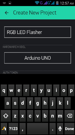
3. Now select Arduino Board and give a name for your project.
4. Note down the Auth Token Code or simply mail it to your Email Account and then copy and paste in Arduino sketch (Program Code).
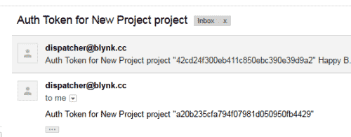
5. Enter this Auth Token Code in Arduino sketch.
// You should get Auth Token in the Blynk App.
// Go to the Project Settings (nut icon).
char auth[] = "a20b235cfa794f07981d050950fb4429";
6. Then click on create button in Blynk app.
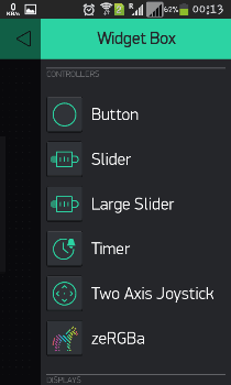
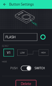
7. Now Select the Large Slider and two buttons, configure them (see the Video at the end) and hit the back button.
8. After it press Play button at the right top of screen.
All this process, of using the Blynk App, has been clearly explained in Video, given in the end.
Required Components:
- Arduino UNO
- ESP8266 Wi-Fi Module
- USB Cable
- Connecting wires
- RGB LED
- Android Mobile phone
- Blynk App
Circuit and Working Explanation:
Circuit Diagram of RGB LED Flasher is given below. We mainly need a Arduino, ESP8266 Wi-Fi module and RGB LED. ESP8266’s Vcc and GND pins are directly connected to 3.3V and GND of Arduino and CH_PD is also connected with 3.3V. Tx and Rx pins of ESP8266 are directly connected to pin 2 and 3 of Arduino. Software Serial Library is used to allow serial communication on pin 2 and 3 of Arduino. We have already covered the Interfacing of ESP8266 Wi-Fi module to Arduino in detail.
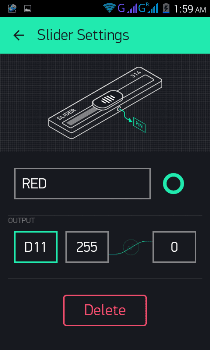
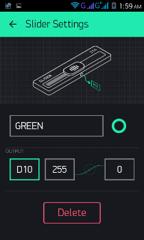
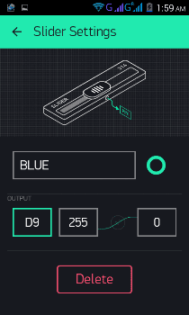
Here we have used a Common Anode RGB LED. This RGB LED pins namely R, G, B and anode are connected at 11, 10, 9 and +5 volt Vcc. Common Anode pin has a 1K resistor with +5 volt for protecting the LED to be damaged.

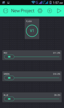
Working of the RGB LED is simple, we have created three Sliders, using Blynk app, for controlling the intensity of three colors of RGB LED that is RED, GREEN and BLUE. And one button for Flashing the RGB LED in different pattern, according to Program code.
Programming Explanation:
First we need to download and install Blynk Library for Arduino.
We have included all the needed libraries to run this code in Arduino IDE, and then entered Auth Token, from the Blynk app, in the auth string. Here we are connecting Wi-Fi serial pin with Software Serial of Arduino. Selected pin 2 as RX and 3 as TX.
#define BLYNK_PRINT Serial    // Comment this out to disable prints and save space
#include <ESP8266_SoftSer.h>
#include <BlynkSimpleShieldEsp8266_SoftSer.h>
// Set ESP8266 Serial object
#include <SoftwareSerial.h>
SoftwareSerial EspSerial(2, 3); // RX, TX
ESP8266 wifi(EspSerial);
// You should get Auth Token in the Blynk App.
// Go to the Project Settings (nut icon).
char auth[] = "a20b235cfa794f07981d050950fb4429";
After it we have defined output pins for RGB LED
#define red 11
#define green 10
#define blue 9
After this, in setup function we initialize all the required devices, begin serial communication, providing Wi-Fi username and password.
void setup()
{
  // Set console baud rate
  Serial.begin(9600);
  delay(10);
  // Set ESP8266 baud rate
  // 9600 is recommended for Software Serial
  EspSerial.begin(9600);
  delay(10);
  Blynk.begin(auth, wifi, "username", "password");  // wifi username and password
}
Then we have checked condition for Button (Virtual Pin 1). Here we have selected virtual pin 1 (V1) for taking input from Blynk App to flash the RGB LED.
Here we should note that, we have attached two codes in our Code section below, first one is just for controlling the intensity of three colors in RGB LED without flashing it and second one is for flashing the LED as well as controlling the three colors of RGB LED. We only need to define RGB Led pins in second program, i.e. Flashing LED program, because Flashing of LED is controlled by Arduino. On the other hand in first program, Colors of LED is controlled by Blynk app in Android phone, so we don’t need to define RGB LED pins.
We can say that if we only want to change the color by Sliders and don’t want to use Button for flasher then we don’t need to define of RGB pins.
The given function is for flashing the RGB LED when button is pressed from the Blynk App.
BLYNK_WRITE(V1)
{
  int x = param[0].asInt();

    while(x==1)
   {
    x = param.asInt();
    int i=0,j=0,k=0;
    analogWrite(red, 255);
    analogWrite(green, 255);
    ... .....
    .... .....
At last we need to run blynk function in loop, to run the system.
void loop()
{
  Blynk.run();
}
Note: Two Codes have been given below. One is for just changing the colors of RGB LED without flasher and second one is for changing the colors with Flasher. Check the Video for more clarity.
Complete Project Code
Code 1: Change the colors of RGB LED without Flasher
#define BLYNK_PRINT Serial    // Comment this out to disable prints and save space
#include <ESP8266_SoftSer.h>
#include <BlynkSimpleShieldEsp8266_SoftSer.h>
// Set ESP8266 Serial object
#include <SoftwareSerial.h>
SoftwareSerial EspSerial(2, 3); // RX, TX
ESP8266 wifi(EspSerial);
// You should get Auth Token in the Blynk App.
// Go to the Project Settings (nut icon).
char auth[] = "a20b235cfa794f07981d050950fb4429";
void setup()
{
  // Set console baud rate
  Serial.begin(9600);
  delay(10);
  // Set ESP8266 baud rate
  // 9600 is recommended for Software Serial
  EspSerial.begin(9600);
  delay(10);
  Blynk.begin(auth, wifi, "1st floor", "muda1884");
}
void loop()
{
  Blynk.run();
}

Code 2: Change the colors of RGB LED with Flasher
#define BLYNK_PRINT Serial    // Comment this out to disable prints and save space
#include <ESP8266_SoftSer.h>
#include <BlynkSimpleShieldEsp8266_SoftSer.h>
// Set ESP8266 Serial object
#include <SoftwareSerial.h>
SoftwareSerial EspSerial(2, 3); // RX, TX
ESP8266 wifi(EspSerial);
// You should get Auth Token in the Blynk App.
// Go to the Project Settings (nut icon).
char auth[] = "a20b235cfa794f07981d050950fb4429";
#define red 11
#define green 10
#define blue 9
void setup()
{
  // Set console baud rate
  Serial.begin(9600);
  delay(10);
  // Set ESP8266 baud rate
  // 9600 is recommended for Software Serial
  EspSerial.begin(9600);
  delay(10);
  Blynk.begin(auth, wifi, "username", "password");  // wifi username and password
}
BLYNK_WRITE(V1)
{
  int x = param[0].asInt();

    while(x==1)
   {
    x = param.asInt();
    int i=0,j=0,k=0;
    analogWrite(red, 255);
    analogWrite(green, 255);
    analogWrite(blue, 255);

      for(int j=0;j<20;j++)
      {
       analogWrite(red, 0);
       analogWrite(green, 255);
       analogWrite(blue, 255);
       delay(100);
       analogWrite(red, 255);
       analogWrite(green, 0);
       analogWrite(blue, 255);
       delay(100);
       analogWrite(red, 255);
       analogWrite(green, 255);
       analogWrite(blue, 0);
       delay(100);
        x = param.asInt();
        if(x==0)
        break;
      }

    analogWrite(red, 255);
    analogWrite(green, 255);
    analogWrite(blue, 255);

    for(int z=0;z<10;z++)
    {
    for(i=0;i<=180;i++)
    {
            analogWrite(red, 180-i);
            delay(2);
    }
    analogWrite(red, 255);
    for(j=0;j<255;j++)
    {
            analogWrite(green, 255-j);
             delay(2);
    }
    analogWrite(green, 255);
    for(k=0;k<255;k++)
    {
            analogWrite(blue, 255-k);
             delay(2);
    }
    analogWrite(blue, 255);
     x = param.asInt();
     if(x==0)
     break;

    }

    analogWrite(red, 255);
    analogWrite(green, 255);
    analogWrite(blue, 255);
        for(int z=0;z<5;z++)
    {
    for(j=0;j<255;j++)
    {
            analogWrite(green, 255-j);
             delay(20);
    }
    for(k=0;k<255;k++)
    {
            analogWrite(blue, 255-k);
             delay(20);
    }

        for(i=0;i<=180;i++)
    {
            analogWrite(red, 180-i);
            delay(20);
    }
    analogWrite(red,180);
     x = param.asInt();
     if(x==0)
     break;
    }
   if(x==0)
   break;
  }
    analogWrite(red, 255);
    analogWrite(green, 255);
    analogWrite(blue, 255);
}
void loop()
{
  Blynk.run();
}
Comments
Install the Blynk Library first, there are lot of tutorials over internet.
my esp8266 is failed to disable echo.. in serial monitor it shows....
[19] Blynk v0.3.4
[520] Connecting to D-Link_DIR-600M
[1537] Failed to disable Echo
how can solve this??????
may be problem in your connection or baud rate mismatch?
suddenly blynk connected to arduino , and suddenly display arduino not in range, or arduino get disconnected?
Can i use a 9v battery powersource for this?
Same here [19] Blynk v0.3.1
[520] Connecting to username
[1536] Failed to disable Echo
Which wifi module are you using? And there are two programs in Code section, In which program you are getting error?
hlo maady how r u give me the you are used libraries link both esp and blynk
Arduino: 1.6.12 (Windows 10), Board: "Arduino/Genuino Uno"
C:\Users\prudhvi dukkipati\Documents\Arduino\leds\leds.ino:2:29: fatal error: ESP8266_SoftSer.h: No such file or directory
#include <ESP8266_SoftSer.h>
^
compilation terminated.
exit status 1
Error compiling for board Arduino/Genuino Uno.
This report would have more information with
"Show verbose output during compilation"
option enabled in File -> Preferences.
Hello Maddy
i really appreciate your work. i am new to this and have problem connecting esp8266 and blynk. In serial monitor i face to failed to disable echo error. how can i solve it?. Any need to flash esp? if yes how?
what are the AT command and how precisely can i run esp82660-01
thanks a million
Am having this issue. help
Arduino: 1.8.5 (Mac OS X), Board: "Arduino/Genuino Uno"
/Users/GeEkMoNkEy/Documents/Arduino/sketch_nov23a/sketch_nov23a.ino:2:29: fatal error: ESP8266_SoftSer.h: No such file or directory
#include <ESP8266_SoftSer.h>
^
compilation terminated.
exit status 1
Error compiling for board Arduino/Genuino Uno.
This report would have more information with
"Show verbose output during compilation"
option enabled in File -> Preferences.

when i copy the code into arduino. it write this error
C:\Users\David\Desktop\sketch_apr14a\sketch_apr14a.ino:2:29: fatal error: ESP8266_SoftSer.h: No such file or directory
#include <ESP8266_SoftSer.h>
^
compilation terminated.
exit status 1
Error compiling for board Arduino/Genuino Uno.