
LEDs are commonly used in electronic circuits as they consume less power, are easy to use, and have a long lifespan. In this tutorial, we will learn how to build an LED ON and OFF circuit using 555 timer IC and BC557.
Required Components
Before we get started, let's understand the components we will be using in this circuit.
- 555 timer IC
- BC557 Transistor
- Resistors -1k*6,56k,47k,200k,100k
- Capacitors-16V 470uf, 16V 10uF
- LEDs
- Power source 12V
555 Timer IC Pinout
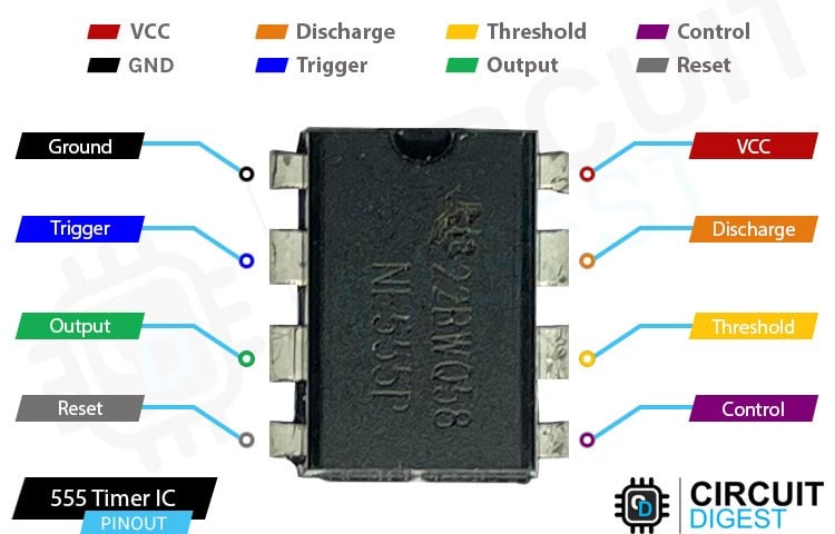
555 timer IC is an electronic component that we use in many electronic projects. It is called a timer because it can be used to control the time for which an electronic device stays on or off.
The 555 timer IC has 8 pins that are numbered from 1 to 8. These pins have different functions, and we connect them to different parts of the circuit to make the timer work the way we want it to.
Here's what each of the pins do:
GND - This pin is connected to the ground, which is the negative side of the power supply. It helps to stabilize the IC and keeps it at a stable voltage.
Trigger - This is the trigger input pin. It is used to start the timer when a voltage is applied to it. When the voltage on this pin drops below one-third of the power supply voltage, the timer is triggered.
Output - This is the output pin. It sends out a voltage signal when the timer is triggered, and this voltage signal can be used to turn on or off other electronic devices.
Reset - This is the reset pin. It is used to reset the timer and stop it from running.
Control - This is the control voltage input pin. It is used to adjust the timing of the 555 timer IC.
Threshold - This is the threshold input pin. It is used to control the timing of the 555 timer IC.
Discharge - This is the discharge pin. It is connected to a capacitor that is used to control the timing of the 555 timer IC.
VCC - This is the power supply pin. It is connected to the positive side of the power supply.
Learn more about 555 Timer IC by following the link.
Circuit Diagram - 555 timer IC based LED ON and OFF Circuit

- Pin 1 of timer 555 IC is the ground pin and is connected to all the grounds in the circuit
- Pin2 of timer 555 IC is the trigger pin which is connected to a 16V10uF capacitor which then connected to the ground pin
- Pin 2 is also connected to the threshold pin (pin number 6) of timer 555 IC
- Pin 3 is the output pin. Which gives a signal to the base terminal of bc557 for driving the led circuit. a 56k resistor is connected between the base of bc557 and output pin of timer 555 IC
- Pin 4 and 5 are floating pins and are not to be connected
- Pin 6 is connected to a 100-k resistor which is parallelly connected to a 200k resistor which ends up connecting to pin 8 (V+)
- Pin 7 is connected between the 100k and 200 k resistor of pin6 and pin8 respectively
- Pin 8(V+) is also connected to emitter of bc557 and the positive terminal of 12v power source
- The gnd terminal of 12v power source is connected to gnd of timer 555 ic
- A 47k resistor and a 16v 470uF capacitor is also connected parallelly to the V+ pin (8th pin) the output of these parallel connection goes to the base terminal of timer 555 ic after the 56k resistor
- The collector terminal of bc557 gives signal to led array so it can light up
Working of the 555 timer IC led ON and OFF Circuit
The led ON and OFF circuit using 555 timer IC and BC557 works on the principle of a multivibrator circuit. A multivibrator circuit is an electronic circuit that produces a square wave output.
In this circuit, the 555 timer IC is configured as an astable multivibrator, which means that it produces a continuous square wave output with a fixed frequency and duty cycle. The frequency and duty cycle of the output waveform can be adjusted by changing the values of the resistors and capacitors connected to the IC.
The output of the 555 timer IC is connected to the base of the BC557 transistor, which acts as a switch. When the output of the 555 timer IC is high, the transistor conducts, allowing current to flow through the LEDs. When the output of the 555 timer IC is low, the transistor turns off, cutting off the current flow through the LEDs.
The LEDs are connected in a sequence, and each LED is connected to the collector of the BC557 transistor through a resistor. The resistors limit the current flowing through the LEDs, protecting them from burning out due to excess current.
When the circuit is powered on, the 555 timer IC generates a continuous square wave output, which is amplified by the BC557 transistor. The amplified output drives the LEDs, creating an ON and OFF effect. The LEDs light up one after the other in a sequence, giving the illusion of movement.
The frequency of the output waveform determines the speed of the ON and OFF effect, while the duty cycle of the waveform determines the brightness of the LEDs. By changing the values of the resistors and capacitors connected to the 555 Timer IC, the frequency and duty cycle of the output waveform can be adjusted, thereby changing the speed and brightness of the LED.
Testing of 555 LED ON and OFF Circuit
This is how the led ON and OFF work using the ic555. The gif above shows how it looks in working condition.
Conclusion
Congratulations! You have successfully built an LED ON and OFF circuit using NE555N and BC557.
When you power on the circuit, the 555 timer IC generates a pulse signal, which is then amplified by the BC557 transistor. The amplified signal drives the LEDs, creating an ON and OFF effect.
In conclusion, LED ON and OFF circuits are an excellent way to add visual effects to your electronic projects by using 555 timer IC and BC557.
