

Audio content has come a long way over the past decades, from a classic tube amp to modern-day media players, technological advancements have changed the way digital media is consumed. Among all these innovations, portable media players have become one of the first choices among consumers, because of their vibrant sound quality and long battery life. So how does it work, and how it sounds that good. As an electronic enthusiast, this question always comes to my mind. Despite advancements in speaker technology, improvements in amplifier methodology played a big role and the obvious answer to this question is a Class D amplifier. So in this project, we will be taking the opportunity to discuss a Class D amplifier and know the pros and cons of it. Finally, we will be building a hardware prototype of the amplifier and testing its performance. Sounds interesting right! So let's get right into it.
If you are interested in audio amplifier circuits, you can check out our articles on the topic where we have built circuits using op-amps, MOSFETs, and IC like TDA2030, TDA2040, and TDA2050.
The Basics of Class D Amplifier
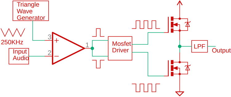
What is a Class-D audio amplifier? The simplest answer will be, it's a switching amplifier. But in order to understand its working, we need to learn how it functions and how the switching signal is produced, for that, you can follow the block diagram given below.
So why a switching amplifier? The obvious answer to this question is Efficiency. Compared to Class A, Class B, and Class AB amplifiers, the Class D audio amplifier can reach an efficiency of up to 90-95%. Where the maximum efficiency of a Class AB amplifier is 60-65%, because they work on the active region and exhibits low power loss, if you multiply collector-emitter voltage with the current, you can find that out. To learn more about the topic, check out our article on classes of power amplifiers where we discussed all the related loss factors.
Now, back to our simplified block diagram of the Class D audio amp, as you can see at the non-inverting terminal, we have our audio input, and on the inverting terminal, we have our high-frequency triangular signal. At this point, when the voltage of the input audio signal is greater than the voltage of the triangular wave, the output of the comparator goes high, and when the signal is low, the output is low. With this setup, we just modulated the input audio signal with a high-frequency carrier signal, which then connects to a MOSFET gate drive IC, and as the name implies, the driver is used to drive the gate of two MOSFETs for both the high side and low side once. At the output, we get a powerful high-frequency square wave at the output, which we pass through a low pass filter stage to get our final audio signal.
Components Required to build Class-D Audio Amplifier Circuit
Now, we have understood the basics of a Class-D audio amplifier and we can move to find the components to build a DIY Class D amplifier. As this is a simple test project, the component requirement is very generic and you can find most of them from a local hobby store. A list of components with a picture is given below.
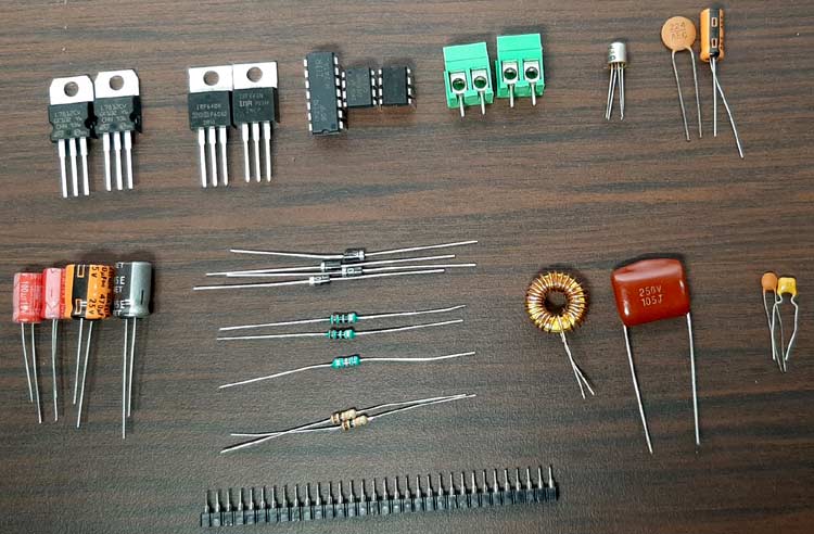
Parts-List to build a Class D Power Amplifier:
- IR2110 IC - 1
- Lm358 OP-Amp - 1
- NE555 Timer IC - 1
- LM7812 IC - 1
- LM7805 IC - 1
- 102 pF Capacitor - 1
- 103 pF Capacitor - 1
- 104 pF Capacitor - 2
- 105 pF Capacitor - 1
- 224 pF Capacitor - 1
- 22uF Capacitor - 1
- 470uF Capacitor - 1
- 220uF Capacitor - 1
- 100uF Capacitor - 2
- 2.2K Resistor - 1
- 10 K Resistor - 2
- 10R Resistor - 2
- 3.5 mm Audio Jack - 1
- 5.08 mm Screw Terminal - 2
- UF4007 Diode - 3
- IRF640 MOSFETs - 2
- 10K Trim POT - 1
- 26uH Inductor - 1
- 3.5 mm Headphone Jack - 1
Class D Audio Amplifier- Schematic Diagram
The schematic diagram for our Class-D amplifier circuit is shown below:

Building the Circuit on PerfBoard
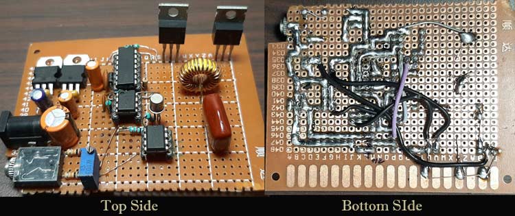
As you can see from the main image, we have made the circuit on a piece of perfboard. Because, first the circuit is very simple, and second if something goes wrong, we can modify it quickly and easily. We made most of the connections with the help of copper wire, but in some final stages, we had to use some hookup wires to complete the build. The completed perfboard circuit is shown below.
Working of Class-D Audio Amplifier
In this section, we will go through every major block of the circuit and explain every block. This Op-amp based Class-D audio amplifier is made up of very generic components that you can find them in your local hobby store.
The Input Voltage Regulators:
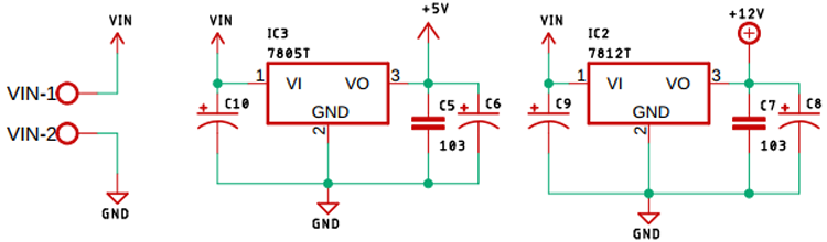
We start by regulating the input voltage with an LM7805, 5V voltage regulator, and an LM7812, a 12 Volt voltage regulator. This is important because we are going to power the circuit with a 13.5V DC adapter, and to power the NE555 and IR2110 IC, 5V and 12V power supply is needed.
Triangular Wave Generator with 555 Astable Multivibrator:
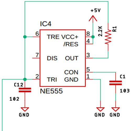
As you can see from the above image, we have used a 555 timer with a 2.2K resistor to generate a 260KHz triangular signal, if you want to know more about Astable Multivibrator, you can check out our previous post on 555 Timer Based Astable Multivibrator Circuit, where we have described all the necessary calculations.
The Modulation Circuit:
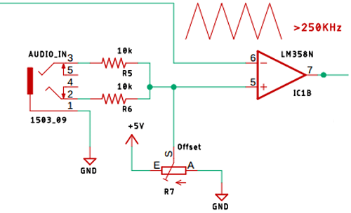
As you can see from the above image, we have used a simple LM358 Op-Amp to modulate the input audio signal. Speaking of incoming audio signals, we have used two 10K input resistors to get the audio signal and as we are using a single supply, we have attached a potentiometer to offset the zero signal present in the input audio. The output of this comparator will be high when the value of the input audio signal is greater than the input triangular wave, and at the output, we will get a modulated square wave, which we then feed to a MOSFET gate driver IC.
The IR2110 MOSFET Gate Driver IC:
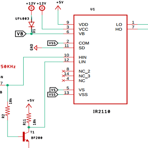
As we are working with some moderately high frequencies, we have used a MOSFET gate driver IC to drive the MOSFET properly. All the necessary circuitry is placed as recommended by the datasheet of IR2110 IC. For proper operation, this IC requires an Inverted signal of the input signal, which is why we have used a BF200, a high-frequency transistor to generate the inverted square wave of the input signal.
The MOSFET Output Stage:
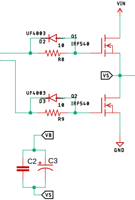
As you can see from the above image, we have the MOSFET output stage, which is also the main output driver, as we are dealing with high frequency and inductors, there are always transients involved, which is why we have used some UF4007 as flyback diodes which prevent the MOSFETs from getting damaged.
The LC Low-Pass Filter:
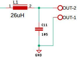
The output from the MOSFET driver stage is a high-frequency square wave, this signal is absolutely inappropriate for driving loads like a loudspeaker. In order to prevent it, we have used a 26uH inductor with a 1uF non-polarized capacitor to make a low pass filter which is denoted as C11. This is how the simple circuit function.
Testing the Class-D Amplifier Circuit
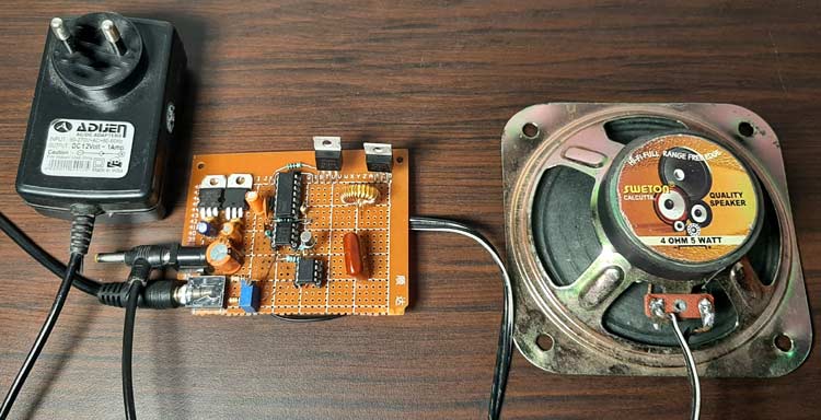
As you can see from the above image, I have used a 12V power adaptor to power the circuit. As I am using an affordable Chinese one, it gives off a little more than the 12V, it's 13.5V to be exact, which is perfect for our onboard LM7812 voltage regulator. As a load, I am using a 4 Ohms, 5Watt speaker. For the audio input, I am using my laptop with a long 3.5mm audio jack.
When the circuit is powered on, there is no noticeable humming sound as you may get from other types of amplifiers, but as you can see on the video, this circuit is not perfect and it has a clipping issue at higher input levels, so this circuit has much room for improvements. As I was driving moderately low loads, the MOSFETs did not get hot at all, and thus for these tests, it doesn't require any heat sink.
Further Enhancements
This Class D power amplifier circuit is a simple prototype and has a lot of room for improvements, My main problem with this circuit was the sampling technique, which needs to be improved. In order to reduce the clipping of the amplifier, proper inductance and capacitance values need to be calculated to get a perfect low pass filter stage. As always, the circuit can be made on a PCB for better performance. A protection circuit can be added that will protect the circuit from overheat or short circuit conditions.
I hope you liked this article and learned something new out of it. If you have any doubt, you can ask in the comments below or can use our forums for detailed discussion.
Comments
Nice Project
The LM358 has officially a slew rate of 0.5 V/µs, although some people have measured 17 V/µs. But both slew rates appear to be too low to make a high speed comparator for PMW generation at 250 kHz. So I would recommend the LM6172 with a maximum slew rate of 3000 V/µs or at least 500 V/µs under the circuit operating conditions.
For the MOSFET driver I would recommend the IR2184 because it can be controlled by a single PWM source. You can also use the IR2183 and connect the single PWM source to both pwm inputs. The lower channel is controlled by an inverting input.
In the first simplified schematic, the audio and triangle inputs are reversed. The actual schematic below that is correct. Otherwise, a very nice project.
Thanks!
What is the value for C2 & C3 is not mentioned in above and what if we used C1,C12 as shown below with the same 100pF for all capacitor values shown below also mentioned the current and power rating for all capacitor and resistors.
- 102 pF Capacitor - 1
- 103 pF Capacitor - 1
- 104 pF Capacitor - 2
- 105 pF Capacitor - 1
How are you going to get pin1 to be 5v higher than OUT2
As you can see there is a boot starting circuit for the MOSFET driver.
Wait we have to use 2 amplifier ( comparator) right? We have to change unit in kicad from A ,B,C what are the connections??

Good ... thanks