
Robots are playing an important role in automation across all the sectors like construction, military, medical, manufacturing, etc. After making some basic robots like line follower robot, computer controlled robot, etc, we have developed this accelerometer based gesture controlled robot by using arduino uno. In this project we have used hand motion to drive the robot. For this purpose we have used accelerometer which works on acceleration.
Required Components
- Arduino UNO
- DC Motors
- Accelerometer
- HT12D
- HT12E
- RF Pair
- Motor Driver L293D
- 9 Volt Battery
- Battery Connector
- USB cable
- Robot Chasis
RF Pair:
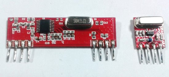
A gesture controlled robot is controlled by using hand in place of any other method like buttons or joystick. Here one only needs to move hand to control the robot. A transmitting device is used in your hand which contains RF Transmitter and accelero-meter. This will transmit command to robot so that it can do the required task like moving forward, reverse, turning left, turning right and stop. All these tasks will be performed by using hand gesture.
Here the most important component is accelerometer. Accelerometer is a 3 axis acceleration measurement device with +-3g range. This device is made by using polysilicon surface sensor and signal conditioning circuit to measure acceleration. The output of this device is Analog in nature and proportional to the acceleration. This device measures the static acceleration of gravity when we tilt it. And gives an result in form of motion or vibration.
According to the datasheet of adxl335 polysilicon surface-micromachined structure placed on top of silicon wafer. Polysilicon springs suspend the structure over the surface of the wafer and provide a resistance against acceleration forces. Deflection of the structure is measured using a differential capacitor which incorporate independent fixed plates and plates attached to the moving mass. The fixed plates are driven by 180° out-of-phase square waves. Acceleration deflects the moving mass and unbalances the differential capacitor resulting in a sensor output whose amplitude is proportional to acceleration. Phase-sensitive demodulation techniques are then used to determine the magnitude and direction of the acceleration.
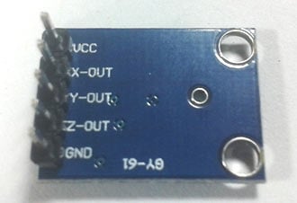
Pin Description of accelerometer
- Vcc 5 volt supply should connect at this pin.
- X-OUT This pin gives an Analog output in x direction
- Y-OUT This pin give an Analog Output in y direction
- Z-OUT This pin gives an Analog Output in z direction
- GND Ground
- ST This pin used for set sensitivity of sensor
Circuit Diagram and Explanation
Gesture Controlled Robot is divided into two sections:
- Transmitter part
- Receiver part
In transmitter part an accelerometer and a RF transmitter unit is used. As we have already discussed that accelerometer gives an analog output so here we need to convert this analog data in to digital. For this purpose we have used 4 channel comparator circuit in place of any ADC. By setting reference voltage we gets a digital signal and then apply this signal to HT12E encoder to encode data or converting it into serial form and then send this data by using RF transmitter into the environment.
At the receiver end we have used RF receiver to receive data and then applied to HT12D decoder. This decoder IC converts received serial data to parallel and then read by using arduino. According to received data we drive robot by using two DC motor in forward, reverse, left, right and stop direction.
Working
Gesture controlled robot moves according to hand movement as we place transmitter in our hand. When we tilt hand in front side, robot start to moving forward and continues moving forward until next command is given.
When we tilt hand in backward side, robot change its state and start moving in backwards direction until other command is given.
When we tilt it in left side Robot get turn left till next command.
When we tilt hand in right side robot turned to right.
And for stopping robot we keeps hand in stable.

Circuit Diagram for Transmitter Section

Circuit Diagram for Receiver Section
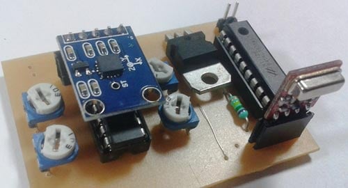
Circuit for this hand gesture controlled robot is quite simple. As shown in above schematic diagrams, a RF pair is used for communication and connected with arduino. Motor driver is connected to arduino to run the robot. Motor driver’s input pin 2, 7, 10 and 15 is connected to arduino digital pin number 6, 5, 4 and 3 respectively. Here we have used two DC motors to drive robot in which one motor is connected at output pin of motor driver 3 and 6 and another motor is connected at 11 and 14. A 9 volt Battery is also used to power the motor driver for driving motors.
Program Explanation
In program first of all we have defined output pins for motors.

And then in setup we have given the directions to pin.

After this we read input by using ‘if statement’ and perform relative operation.

There are total five conditions for this Gesture controlled Robot which are giving below:
Movement of hand | Input for Arduino from gesture | ||||
Side | D3 | D2 | D1 | D0 | Direction |
Stable | 0 | 0 | 0 | 0 | Stop |
Tilt right | 0 | 0 | 0 | 1 | Turn Right |
Tilt left | 0 | 0 | 1 | 0 | Turn Left |
Tilt back | 1 | 0 | 0 | 0 | Backward |
Tilt front | 0 | 1 | 0 | 0 | Forward |
We have writen the complete program according to the above table conditions. Below is the complete code.
Complete Project Code
#define FD 16
#define BD 17
#define LD 18
#define RD 19
#define m11 3
#define m12 4
#define m21 5
#define m22 6
void forward()
{
   digitalWrite(m11, HIGH);
   digitalWrite(m12, LOW);
   digitalWrite(m21, HIGH);
   digitalWrite(m22, LOW);
}
void backward()
{
   digitalWrite(m11, LOW);
   digitalWrite(m12, HIGH);
   digitalWrite(m21, LOW);
   digitalWrite(m22, HIGH);
}
void left()
{
   digitalWrite(m11, HIGH);
   digitalWrite(m12, LOW);
   digitalWrite(m21, LOW);
   digitalWrite(m22, LOW);
}
void right()
{
   digitalWrite(m11, LOW);
   digitalWrite(m12, LOW);
   digitalWrite(m21, HIGH);
   digitalWrite(m22, LOW);
}
void Stop()
{
   digitalWrite(m11, LOW);
   digitalWrite(m12, LOW);
   digitalWrite(m21, LOW);
   digitalWrite(m22, LOW);
}
void setup()
{
  pinMode(FD, INPUT);
  pinMode(BD, INPUT);
  pinMode(LD, INPUT);
  pinMode(RD, INPUT);
  pinMode(m11, OUTPUT);
  pinMode(m12, OUTPUT);
  pinMode(m21, OUTPUT);
  pinMode(m22, OUTPUT);
}
void loop()
{
  int temp1=digitalRead(FD);
  int temp2=digitalRead(BD);
  int temp3=digitalRead(LD);
  int temp4=digitalRead(RD);

  if(temp1==1 && temp2==0 && temp3==0 && temp4==0)
  backward();
  else if(temp1==0 && temp2==1 && temp3==0 && temp4==0)
  forward();
  else if(temp1==0 && temp2==0 && temp3==1 && temp4==0)
  left();
  else if(temp1==0 && temp2==0 && temp3==0 && temp4==1)
  right();
  else
  Stop();
}
Comments
can you please tell me which rf pair should i use? Also can i use atmega8 instead of Arduino UNO?
@Vikram @Jayesh This is ASK RF module Wireless Transmitter & Receiver Pair - 433MHz. It has apporx 100 meter range when operated at max supply voltage (12v). Check its more detail (with images) in this project: RF controlled Robot
I like this project but i dont know how to give program to the robot
Arduino IDE software (Arduino Nightly : https://www.arduino.cc/en/Main/Software) is used to write, verify and upload/burn the code into Arduino, through PC
Nice approach
Can we use transmitting ckt with out cmos
What is value of variable resistor set for transmitter circuit?
Please give me PCB layout of this circuit
Good one !
Hey friend!! Firstly i would like to thank u for uploading this project.
I am also making the same project as urs using the same diagram and code and everything but i am not able to successfully run it.Pls help me asap as i hv to submit my project in 3-4 days.
I have used same connection and the led on receiver is also glowing but i am not able to figure out the problem as motors r not running.
The information is not sufficient, without looking into your code and circuit, we cant help.
Hi Abhishek,
This is regarding Accelerometer based hand gesture robot project which u had uploaded in the web. I am unable to get the output . I guess there is a bug in the program. I haave done the same connections and uploaded thr program bit the motors aren't running. I then added baurd rate 9600 into program and added few line of codes but still i am not able ro run the motors. I have used the same hardware components and connectionss which u had done.
Below is my source code pls check wat is the bug.
#define FD 16
#define BD 17
#define LD 18
#define RD 19
#define m11 3
#define m12 4
#define m21 5
#define m22 6
void forward()
{
digitalWrite(m11, HIGH);
digitalWrite(m12, LOW);
digitalWrite(m21, HIGH);
digitalWrite(m22, LOW);
}
void backward()
{
digitalWrite(m11, LOW);
digitalWrite(m12, HIGH);
digitalWrite(m21, LOW);
digitalWrite(m22, HIGH);
}
void left()
{
digitalWrite(m11, HIGH);
digitalWrite(m12, LOW);
digitalWrite(m21, LOW);
digitalWrite(m22, LOW);
}
void right()
{
digitalWrite(m11, LOW);
digitalWrite(m12, LOW);
digitalWrite(m21, HIGH);
digitalWrite(m22, LOW);
}
void Stop()
{
digitalWrite(m11, LOW);
digitalWrite(m12, LOW);
digitalWrite(m21, LOW);
digitalWrite(m22, LOW);
}
void setup()
{
Serial.begin(9600);
pinMode(FD, INPUT);
pinMode(BD, INPUT);
pinMode(LD, INPUT);
pinMode(RD, INPUT);
pinMode(m11, OUTPUT);
pinMode(m12, OUTPUT);
pinMode(m21, OUTPUT);
pinMode(m22, OUTPUT);
}
void loop()
{
int temp1=digitalRead(FD);
int temp2=digitalRead(BD);
int temp3=digitalRead(LD);
int temp4=digitalRead(RD);
Serial.print(analogRead(FD));
Serial.print("\t");
Serial.print(analogRead(BD));
Serial.print("\t");
Serial.print(analogRead(LD));
Serial.print("\t");
Serial.print(analogRead(RD));
Serial.println();
delay(100);
if(temp1==1 && temp2==0 && temp3==0 && temp4==0)
backward();
else if(temp1==0 && temp2==1 && temp3==0 && temp4==0)
forward();
else if(temp1==0 && temp2==0 && temp3==1 && temp4==0)
left();
else if(temp1==0 && temp2==0 && temp3==0 && temp4==1)
right();
else
Stop();
}
Can I use the same code to drive stepper motors?
No, you can't.
I'm new to this rf things...can u explain to me the use of Use of encoder nd decoders
Hello,
I built a transmitter module on a bread board and it looks really clumsy because of too many connecting wires and potentiometers. It's too large for a hand palm. However, in the video that you have uploaded, transmitter looks really small. So, kindly upload a picture of the transmitter module alone so that I'll get some idea of optimizing the design.
Should we connect all the components as it is shown in the transmitter and receiver diagrams?
i can not find any accelerometer sensor in proteus.......also encoder-decoder HT12E & HT12D....please help me how to find this component in proteus.......Badly need this component to simulate this project
I want where you have simulated this circuit, coz I can't find all the components used in Proteus.
if anyone have the simulated file for this project please mail me
I built a transmitter module on a bread board and it looks really clumsy because of too many connecting wires and potentiometers. It's too large for a hand palm. However, in the video that you have uploaded, transmitter looks really small. So, kindly upload a picture of the transmitter module alone so that I'll get some idea of optimizing the design.
Please reply as soon as possible. The project deadline is approaching and I badly need a help in building the transmitter module.
@Megashree @Hadmath Please check, we have uploaded the Image of Transmitter.
I am not able to make the led on the receiver side glow pls help..
Hey friend!! Firstly i would like to thank u for uploading this project.
I am also making the same project as yours using the same diagram and code and everything but i am not able to successfully run it. Please help me asap as i have to submit my project in 3-4 days.
I have used same connection and the led on receiver is also glowing but i am not able to figure out the problem as motors are not running.
Should the antenna pin of transmitter and receiver modules be left as it is? or should we connect any coil to that pin?
hi friend, im doing a similar project to this one. can you please help me with this, which circuit simulator did you use because i cant find most of these components on Proteus. looking forward for your reply. Thank you.
I can not upload code into arduino uno r3.
The error is:-
avrdude: stk500_recv(): programmer is not responding
avrdude: stk500_getsync() attempt 1 of 10: not in sync: resp=0x43
avrdude: stk500_recv(): programmer is not responding
avrdude: stk500_getsync() attempt 2 of 10: not in sync: resp=0x43
avrdude: stk500_recv(): programmer is not responding
avrdude: stk500_getsync() attempt 3 of 10: not in sync: resp=0x43
avrdude: stk500_recv(): programmer is not responding
avrdude: stk500_getsync() attempt 4 of 10: not in sync: resp=0x43
avrdude: stk500_recv(): programmer is not responding
avrdude: stk500_getsync() attempt 5 of 10: not in sync: resp=0x43
avrdude: stk500_recv(): programmer is not responding
avrdude: stk500_getsync() attempt 6 of 10: not in sync: resp=0x43
avrdude: stk500_recv(): programmer is not responding
avrdude: stk500_getsync() attempt 7 of 10: not in sync: resp=0x43
avrdude: stk500_recv(): programmer is not responding
avrdude: stk500_getsync() attempt 8 of 10: not in sync: resp=0x43
avrdude: stk500_recv(): programmer is not responding
avrdude: stk500_getsync() attempt 9 of 10: not in sync: resp=0x43
avrdude: stk500_recv(): programmer is not responding
avrdude: stk500_getsync() attempt 10 of 10: not in sync: resp=0x43
please tell me how can i solve this error
Is the program correct for sure or is there any other program.
My robot is only going forward. What could be wrong? Please help....
Program and Circuits are complete and correct, make sure you did the right connections.
im unable to connect the transmitter circuit which he has given.... the problem is connections with the 4 presets that he had used.... please help me out
hi i would like to know how you calibrated the accelerometer
can u please help with circuit design??
What is the model no. of the accelerometer used here?and I don't find l293d motor driver,Does any other motor driver work?
I dont find this model of motor driver L293D.Will any other motor driver work? I dont see 4 input pins in other motor driver like L293D.At that situation which pins i use to connect to Arduino?
Its Accelerometer Sensor ADXL335. And L293D is very common IC, are you sure that it is not available?
i cant find components for making this on proteus how did u done it on proteus
What modul transmitter and receiver do you use.?
This is ASK Hybrid Transmitter and receiver RF module operates at 433Mhz frequency.
i built all the circuit but still its not doing a thing,what might be wrong???
Can i use xbee instead of rf?
yes
HELLO.
I HAVE MADE THE EXACT CIRCUIT FOR Rx AND Tx, & USED THE EXACT SAME CODE.
BUT IT IS NOT WORKING CORRECTLY.
SOMETIME MOTORS HAVE TURNED ON WHILE OTHERTIME THEY DONT,
PLEASE HELP SORTING THIS OUT.
What can this be used for?
Is there needed any header file such as for decoder,motor driver?I connected all elements exactly as like as your provided figure but when i test it there is no signal in the receiver portion and robot does not run too.
Upto what range it will work when u stand at a constant place
This question is already answered in above comments, please check. Further this RF module has approx 100 meter range when operated at max supply voltage (12v)
what are m11,m12,m21,m22 you used in the code?
hai i like this robot,but actually i am new to this gesture things. can ypu please give me the assembling of parts in both reciever and transmitter section as avideo
hiw to create the pcb board
Check this article How to make a PCB at home? or you can directly design and order PCB from many online tools like EasyEDA, check this: Design Your Circuits Online for Free with EasyEDA
When I did the project.The motor doesn't run when I apply gesture.But when I touch or change the resistance using screwdriver the motor runs.pls give the solution.
you first need to adjust all the 4 Variable resistor in stable position.
Sir then what I have to do sir.
Sie how u make transmitter connections..on PCB..it too complicated .....plz help me
Ll
What will happen if A1-A7 pins are left as it is??(both in encoder and decoder)
A0-A7 pins should be identically configured. We have grounded them in both encoder and decoder. You can make many combinations like left A0 open in encoder and same in decoder, then this encoder will only respond for A0 opened decoder.
i have made the all connection as shown in the circuit diagram nd same program but..its not working... led is also not glowing in the receiver circuit.. plzzz help ..i did not find the sollution yet ..plzz help me its urgent
what software do you used to simulate this circuit ??
can you please tell ,me how to simulate reciver circuit in proteus
I have made this robot bt in the transmitter section I have implemented the accelerometer in such a direction that yours x-y direction is mine y- x direction so what changes should I make in my program plzzzz help me
i make this project but cant run it is i need to programe HT12E AND HT12D
I COMPLETE THE BOTH TRANSMITER ANS RECEIVER AND I USE H BRIDGE
I have connected all the components asper the circuit, but when I tilt the accelerometer forward and right the motors moves forward and right, but when the accelerometer is tilted left and backwards the motors aren't moving! please help me! What should I do
hi.
my robot's motor does not run.. please help me
Plz help me can I use the h.bridge instead of motor driver ic.
Sir according table in forward 1 pin is high.but in program you write the two pins are high for forward.please explain it.plzplzplZ.which condition is true for forward and other
Table's D3,D2,D1,D0 are related to variables Temp1, temp2, temp3, temp4, not related with the Motors pins which you are talking about, please check carefully.
hey sir. can u help me. i cant find ht12e and ht12d in my library of proteus. do you have the library for that in proteus 8? can u email it to me or what do you use to draw the circuit and simulation
ht12e and ht12d are not there in Proteus you can try using IC M145026 and M145027. These ICs work same like ht12e and ht12d.
Sir can I use diffrent conditin for left and right movment because my car is going only forward and backward.in program 1 pin high for left and right can i set 2 pins high.because it is very difficult to set the condition for left and right from variable resister.give me salution
thanks sir for guidess i copleted the project.my car is working.thanks sir
Hi Umar,
We are glad that it worked for you.
Hey! This is my first project so I'm just gonna replicate it. Is the information and code available on the website sufficient ?
pls reply! it'll help alot.
Hey plz help me in m not getting the output...
Please give me the pcb layout of this ckt diagram
Please tell mi, Can i use arduino nano for the similar project?? What will be the changes in circuit and code?
Hii Friends,
I would like to thank you for uploading this project'
I have used same hardware components,same circuit connections & code. I have also included the "Serial.begin(9600);" baudrate instrution in the "void setup()" function and "delay(100);" and few "Serial.print(.......) instuctions;" in the "void loop()" function. I am getting the output in software. But, the motors are not running.
I have few confusion in motor driver(L293D) circuit of receiver section. Is pin 16,1,8,9 all are shorted and given to 5V of Arduino? And for which pin 9V battery is connected to? because,according to data sheet of L293D pin 1,9,16 r given to 5V and pin 8 is given to battery. So,I did the connections correctly but unable to get the output(motors are not running). In the picture of project module which u uploaded I can see 2 wires in between analog and digital pins of Arduino board. But unable to get to where those pins are connected to. Please upload the receiver circuit connection and clear picture of your project module. once again. So that it may clear my doubts. Tell me if there any bug in it and Please clear my doubts within the 2days.
Pin 1,9,16 are shorted and connected to 5v and pin 8 is connected 9v battery and Click on the circuit to enlarge it.
Hi there,
can u hlp me connecting accelerometer with the data lines of encoder.there is only x and y axis ryt and 4 data pins for encoder.in the circuit it is shunted ryt?i have a rf encoder board where i can connect the the transmitter module.
Thanks :)
All the connections are given in the circuit, and if your modules are different than presented here, then refer datasheets of them for the connections.
Please help me I used same connection and codings but out put not came
can u give me the pcb layout of ur both circuits i have to make this project urgently and dont have much time , kindly give me pcb layout ....
can you tell me that can I use a microcontroller directly instead of ardunio board

Can you please tell me the range of the RF ? I mean for what distance can I use this RF ? Are there ant better ways to transmit the commands ?