
Distance measurement of an object in the path of the person, equipment, or a vehicle or moving object is used in a large number of applications such as robotic movement control, vehicle control, blind man’s walking stick, medical equipment, etc. There are many methods available for distance measurement but measurement using Ultrasonic sensor is one of the cheapest among other options. In this project, we are going to use HC-SR04 Ultrasonic Sensor with ATtiny85 microcontroller IC and OLED display module to build a digital ultrasonic ruler. We have built this project on PCB and have used PCBWay to fabricate the boards for this project. In the following sections of the article, we have covered in detail the complete procedure to design, order, and assemble the PCB boards for this ultrasonic ruler so that you can also easily build one on your own.
This board can be used for distance measurement, object detection, and many other applications. Also, if you are interested in building more measuring devices using Arduino, you can also check out this Arduino Digital Protractor which we built previously.
Components Required for Ultrasonic Ruler
- ATtiny85 IC
- HC-SR04 Ultrasonic Sensor
- I2C OLED Display Module
- AMS1117 5V Voltage Regulator
- 3× 10KΩ Resistor
- 1× 10 µf Capacitor
- 9V Battery
Ultrasonic Digital Ruler Circuit Diagram
The schematic for the Ultrasonic Ruler using ATtiny85 is given below:

The above image shows the circuit diagram for interfacing Ultrasonic Sensor and OLED Display with Attiny85 IC. The interface between OLED Display and ATtiny85 must be implemented using I2C Protocol. Hence, the SCL Pin (PB2) of the ATtiny85 is connected to the SCL Pin of the OLED Display. Similarly, the SDA Pin (PB0) of the ATtiny85 is connected to the SDA Pin of OLED Display. Echo and Trig pins of Ultrasonic sensor are connected to PB3 and PB4 pins of ATtiny85 respectively. Finally, to power all the components, we have used the 9V battery. This 9V is then converted to 5V using an AMS117-5V voltage regulator.
Note: Follow our previous tutorials Programming ATtiny85 IC directly through USB using Digispark Bootloader or Programming ATtiny85 using Arduino to program the ATtiny85 IC.
Fabricating PCB for Ultrasonic Ruler
Now that we have the schematic, and we can proceed with laying out the PCB for Ultrasonic range finder using ATtiny85. You can design the PCB using any PCB software of your choice.
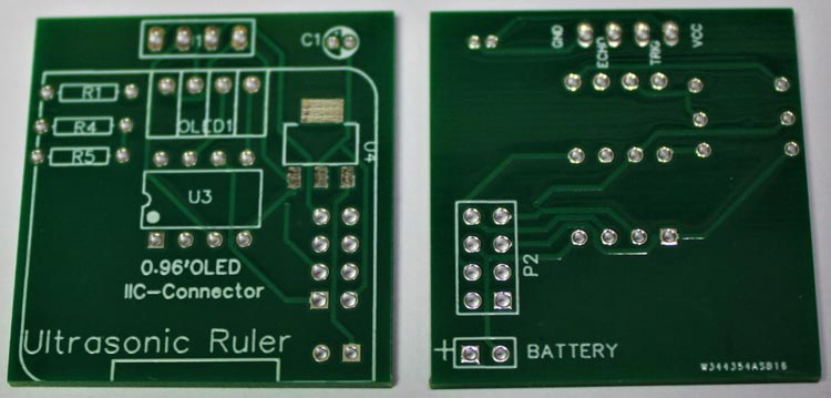
Below are the 3D model views of the top layer and bottom layer of the Ultrasonic Ruler PCB:
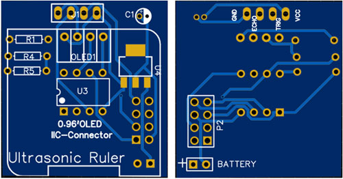
The PCB layout for the above circuit is also available for download as Gerber from the link given below:
Gerber file for ATtiny85 Ultrasonic Ruler
Ordering PCB from PCBWay
Now after finalizing the design, you can proceed with ordering the PCB:
Step 1: Get into https://www.pcbway.com/, sign up if this is your first time. Then, in the PCB Prototype tab, enter the dimensions of your PCB, the number of layers, and the number of PCB you require.
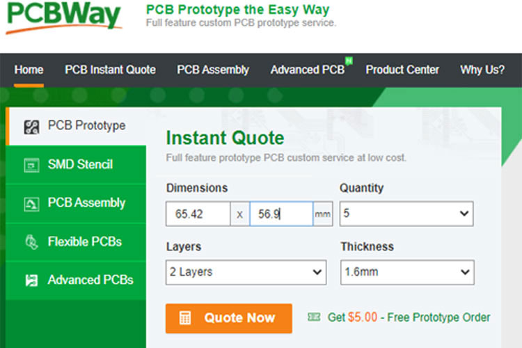
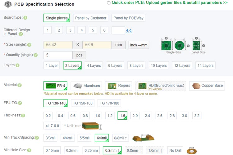
Step 2: Proceed by clicking on the ‘Quote Now’ button. You will be taken to a page to set a few additional parameters like the Board type, Layers, Material for PCB, Thickness, and More, most of them are selected by default, if you are opting for any specific parameters, you can select it in here.
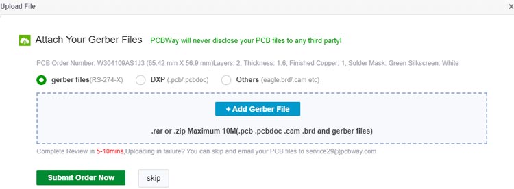
Step 3: The final step is to upload the Gerber file and proceed with the payment. To make sure the process is smooth, PCBWAY verifies if your Gerber file is valid before proceeding with the payment. This way, you can be sure that your PCB is fabrication friendly and will reach you as committed.
Assembling the Attiny85 Ultrasonic Ruler PCB
After a few days, we received our PCB in a neat package and the PCB quality was good as always. The top layer and the bottom layer of the board are shown below:
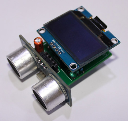
After making sure the tracks and footprints were correct. I proceeded with assembling the PCB. The completely soldered board looks like the below:

ATtiny85 Ultrasonic Ruler Code Explanation
The complete Arduino step counter code is given at the end of the document. Here we are explaining some important parts of the code.
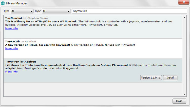
The code uses the TinyWireM.h & TinyOzOLED.h libraries. The TinyWireM library can be downloaded from the Library Manager in the Arduino IDE and install from there. For that, open the Arduino IDE and go to Sketch < Include Library < Manage Libraries. Now search for TinyWireM.h and install the TinyWireM library by Adafruit.
While the TinyOzOLED.h library can be downloaded from the given link.
After installing the libraries to Arduino IDE, start the code by including the needed libraries files.
#include "TinyWireM.h"
#include "TinyOzOLED.h"
In the next lines, define the ultrasonic sensor pins. We have defined the trig and echo pins of ultrasonic sensor as shown below.
const int trigPin = 4; //P4
int echoPin = 3; //P3
Then comes the setup() function. This is where we define the ATtiny85 pins as input/output and start the communication between ATtiny85 and OLED.
void setup() {
  TinyWireM.begin();
  OzOled.init();
  OzOled.clearDisplay();
  OzOled.setNormalDisplay();
  OzOled.sendCommand(0xA1);
  OzOled.sendCommand(0xC8);
  pinMode(trigPin, OUTPUT);
}
Now inside the loop() function, we first measure the distance using ultrasonic sensor and then display it on OLED display. To measure the distance using ultrasonic sensor, first, you have to set trigpin LOW State for just 2 µs to make sure that it is clear. Now for generating the Ultra sound wave, set the trigPin HIGH for 10 µs. After this, use the pulseIn() function to read the travel time and store the readings into the variable called “duration”. pulseIn() function has 2 parameters, the first one is the name of the echo pin and the second one is the state of echo pin. Then after getting the distance, we displayed it on OLED display.
digitalWrite(trigPin, LOW);
delayMicroseconds(2);
digitalWrite(trigPin, HIGH);
delayMicroseconds(10);
digitalWrite(trigPin, LOW);
pinMode(echoPin, INPUT);
duration = pulseIn(echoPin, HIGH);
cm = microsecondsToCentimeters(duration);
OzOled.printString("Distance:", 3, 4);
OzOled.printNumber(cm, 0, 12, 4);
Testing our Ultrasonic Ruler
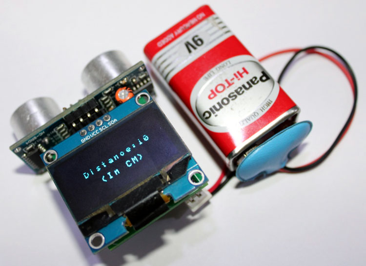
After assembling the PCB and programming ATtiny85 for distance measurement, we can now test the Ultrasonic ruler. For that, power the board using 9V and wait until the measured distance is displayed on OLED display. You can use a scale or measurement tape to check if the measured distance is correct or not.
A full working video and code can be found below. Hope you enjoyed the project and learned something useful, if you have any questions, please leave them in the comment section below or use our forums to start a discussion on this.
Complete Project Code
#include "TinyWireM.h"

#include "TinyOzOLED.h"

const int trigPin = 4; //P4

int echoPin = 3; //P3

int duration, cm;

void setup() {

  TinyWireM.begin();

  OzOled.init();

  OzOled.clearDisplay();

  OzOled.setNormalDisplay();

  OzOled.sendCommand(0xA1);        // set Orientation

  OzOled.sendCommand(0xC8);

  pinMode(trigPin, OUTPUT);

}

void loop()

{

//OzOled.clearDisplay();

digitalWrite(trigPin, LOW);

delayMicroseconds(2);

digitalWrite(trigPin, HIGH);

delayMicroseconds(10);

digitalWrite(trigPin, LOW);

//setting up the input pin, and receiving the duration in uS

pinMode(echoPin, INPUT);

duration = pulseIn(echoPin, HIGH);

// convert the pulse travel time into a distance

cm = microsecondsToCentimeters(duration);

displayOLED();

delay(1000);

OzOled.clearDisplay();

}

void displayOLED() {

  OzOled.printString("Distance:", 3, 3);

  OzOled.printNumber(cm, 0, 12, 3);

  OzOled.printString("(In CM)", 5, 5);

}

long microsecondsToCentimeters(long microseconds)

{

// The speed of sound is 340 m/s (29 us/cm)

return microseconds / 29 / 2;

}
Comments
You may think PCBWay is a
You may think PCBWay is a great source, but they wanted to charge me $46 shipping on a $6 order. And I live in Texas, not some difficult out-of-the-way location. Their shipping rates border on being an out-right scam.
I am not able to compile this
I am not able to compile this code file, could somebody provide the ,hex file?
Looks interesting. I'm…
Looks interesting. I'm gonna try this one.
So, another post tells me to install the damelis attiny board package into Arduino IDE as a first step?

Are you actually joking? Have YOU tried to gety a ATTiny ANYTHING in the past 6 months?