
The MPU6050 is an IC 3-axis accelerometer and a 3-axis gyroscope combined into one unit. It also houses a temperature sensor and a DCM to perform a complex task. The MPU6050 is commonly used in building Drone and other remote robots like a self-balancing robot. In this project we will build a Digital Protractor using MPU6050 and Arduino. Here a servo motor is used to display the angle on a protractor image. Servo motor shaft is attached with a needle which will rotate on protractor image to indicate the angle which is also displayed on a 16xLCD display. Before going into details let's learn about Gyroscope sensor.
What is an Accelerometer and Gyroscopic sensor?
An accelerometer is used to measure the acceleration. It actually senses both the static and dynamic acceleration. For example, mobile phones use accelerometer sensor to sense that the mobile is on landscape mode or portrait mode. We previously used Accelerometer with Arduino to build many projects like:
- Ping Pong Game using Arduino and Accelerometer
- Arduino Based Vehicle Accident Alert System using GPS, GSM and Accelerometer
- Accelerometer Based Hand Gesture Controlled Robot using Arduino
- Earthquake Detector Alarm using Arduino
A gyroscope is used to measure angular velocity that uses earth’s gravity to determine the orientation of the object in motion. Angular velocity is the rate of change of angular position of a rotating body.
For example, todays mobiles use gyroscopic sensors to play mobile games according to the orientation of the mobile phone. Also, VR headset uses gyroscope sensor to have views in 360 orientation
So while accelerometer can measure linear acceleration, gyroscope can help find the rotational acceleration. When using both the sensors as separate modules it becomes difficult to find orientation, position and velocity. But by combining the two sensors it works as an Inertial Measurement Unit (IMU). So in MPU6050 module, accelerometer and gyroscope are present on a single PCB to find the orientation, position and velocity.
Applications:
- Used in Drones for direction control
- Self-balancing robots
- Robotic arm control
- Tilt sensor
- Used in Mobile phones, Video game consoles
- Humanoid Robots
- Used in Aircraft, Automotive etc.
MPU6050 Accelerometer and Gyroscopic Sensor Module
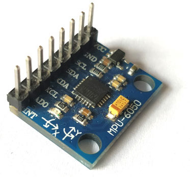
The MPU6050 is a Micro Electro-Mechanical Systems (MEMS) which consists of a 3-axis Accelerometer and 3-axis Gyroscope inside it. It also has temperature sensor.
It can measure:
- Acceleration
- Velocity
- Orientation
- Displacement
- Temperature
This module also has a (DMP) Digital Motion Processor inside it which is powerful enough to perform complex calculation and thus free up the work for Microcontroller.
The module also has two auxiliary pins which can be used to interface external IIC modules like a magnetometer. Since the IIC address of the module is configurable, more than one MPU6050 sensor can be interfaced to a Microcontroller using the AD0 pin.
Features & Specifications:
- Power Supply: 3-5V
- Communication: I2C protocol
- Built-in 16-bit ADC provides high accuracy
- Built-in DMP provides high computational power
- Can be used to interface with other IIC devices like magnetometer
- Configurable IIC Address
- In-built Temperature sensor
Pinout of MPU6050:
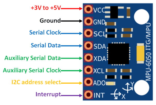
| Pin Number | Pin Name | Use |
| 1 | Vcc | Provides power for the module, can be +3V to +5V. Typically +5V is used |
| 2 | Ground | Connected to Ground of system |
| 3 | Serial Clock (SCL) | Used for providing clock pulse for I2C Communication |
| 4 | Serial Data (SDA) | Used for transferring Data through I2C communication |
| 5 | Auxiliary Serial Data (XDA) | Can be used to interface other I2C modules with MPU6050. It is optional |
| 6 | Auxiliary Serial Clock (XCL) | Can be used to interface other I2C modules with MPU6050. It is optional |
| 7 | AD0 | If more than one MPU6050 is used a single MCU, then this pin can be used to vary the address |
| 8 | Interrupt (INT) | Interrupt pin to indicate that data is available for MCU to read. |
We previously used MPU6050 with Arduino to build Self Balancing Robot and Inclinometer.
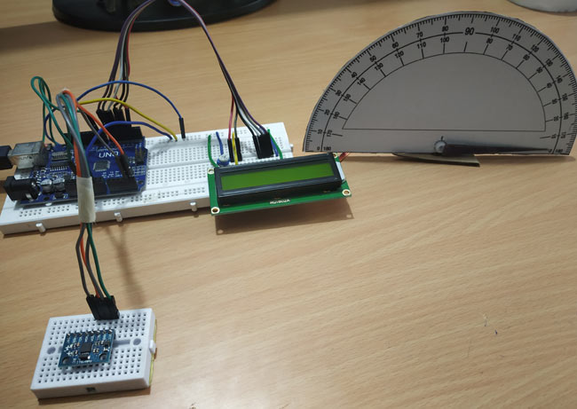
Components Required
- Arduino UNO
- MPU6050 Gyroscope Module
- 16x2 LCD Display
- Potentiometer 10k
- SG90-Servo Motor
- Protractor Image
Circuit Diagram
Circuit diagram for this DIY Arduino Protractor is given below:

Circuit Connections between Arduino UNO and MPU6050:
MPU6050 | Arduino UNO |
VCC | +5V |
GND | GND |
SCL | A5 |
SDA | A4 |
Circuit Connections between Arduino UNO and Servo Motor:
Servo Motor | Arduino UNO |
RED (VCC) | +5V |
ORANGE (PWM) | 9 |
BROWN (GND) | GND |
Circuit Connections between Arduino UNO and 16x2 LCD:
LCD | Arduino Nano |
VSS | GND |
VDD | +5V |
V0 | To Potentiometer Centre PIN For Controlling Contrast of the LCD |
RS | 2 |
RW | GND |
E | 3 |
D4 | 4 |
D5 | 5 |
D6 | 6 |
D7 | 7 |
A | +5V |
K | GND |
Programming Explanation
As usual the complete program with a Demonstration video is given at the end of this tutorial.
Here servo motor is connected with Arduino and its shaft is projected on protractor image indicating the angle of the inclined MPU6050. Programming for this tutorial is simple. Let’s see it in detail.
First include all the required libraries - Servo Motor library for using Servo, LCD library for using LCD and Wire library for using I2C communication.
The MPU6050 uses I2C Communication and hence, it must be connected only to the I2C Pins of the Arduino. So, Wire.h library is used to establish communication between Arduino UNO and MPU6050. We previously interfaced MPU6050 with Arduino and displayed the x,y,z coordinate values on 16x2 LCD.
#include <Servo.h>
#include <LiquidCrystal.h>
#include <Wire.h>
Next define LCD display pins RS, E, D4, D5, D6, D7 that are connected with Arduino UNO.
LiquidCrystal lcd(2,3,4,5,6,7);
Next the I2C address of the MPU6050 is defined.
const int MPU_addr=0x68;
Then initialize myservo object for using Servo class and three variables to store X, Y and Z axis values.
Servo myservo;
int16_t axis_X,axis_Y,axis_Z;
Next minimum and maximum value is set as 265 and 402 for measuring angle from 0 to 360.
int minVal=265;
int maxVal=402;
void setup():
In void setup function first I2C communication is started and transmission has begun with MPU6050 with address of 0x68.
  Wire.begin();
  Wire.beginTransmission(MPU_addr);
Put the MPU6050 in Sleep Mode by writing 0x6B and then awake the it by writing 0
Wire.write(0x6B);
Wire.write(0);
After making MPU6050 active, end the transmission
Wire.endTransmission(true);
Here the PWM pin of Servo motor is connected with Arduino UNO pin 9.
myservo.attach(9);
As soon as we power up the circuit the LCD displays a welcome message and clear it after 3 seconds
 lcd.begin(16,2);                 //Sets LCD in 16X2 Mode
  lcd.print("CIRCUIT DIGEST");
  delay(1000);
  lcd.clear();
  lcd.setCursor(0,0);
  lcd.print("Arduino");
  lcd.setCursor(0,1);
  lcd.print("MPU6050");
  delay(3000);
lcd.clear();
void loop():
Again, the I2C communication is begun with MPU6050.
Wire.beginTransmission(MPU_addr);
Then start with register 0x3B (ACCEL_XOUT_H)
Wire.write(0x3B);
Now the process is restarted by set end transmission as false but the connection is active.
Wire.endTransmission(false);
After that now request the data from the 14 registers.
Wire.requestFrom(MPU_addr,14,true);
Now respected axis register values (x, y, z) are obtained and stored in variables axis_X,axis_Y,axis_Z.
  axis_X=Wire.read()<<8|Wire.read();
  axis_Y=Wire.read()<<8|Wire.read();
  axis_Z=Wire.read()<<8|Wire.read();
Then map those values from 265 to 402 as -90 to 90. This is done for all the three axes.
    int xAng = map(axis_X,minVal,maxVal,-90,90);
    int yAng = map(axis_Y,minVal,maxVal,-90,90);
    int zAng = map(axis_Z,minVal,maxVal,-90,90);
Formula to calculate x value in degree (0 to 360) is given below. Here we convert only x because the servo motor rotation is based on x value movement.
x= RAD_TO_DEG * (atan2(-yAng, -zAng)+PI);
X angle value, from 0 to 360 deg, is converted into 0 to 180.
int pos = map(x,0,180,0,180);
Then write the angle value to rotate the servo on protractor image and Print those values on the 16x2 LCD display.
 myservo.write(pos);
lcd.setCursor(0,0);
lcd.print("Angle");
lcd.setCursor(0,1);
lcd.print(x);
delay(500);
lcd.clear();
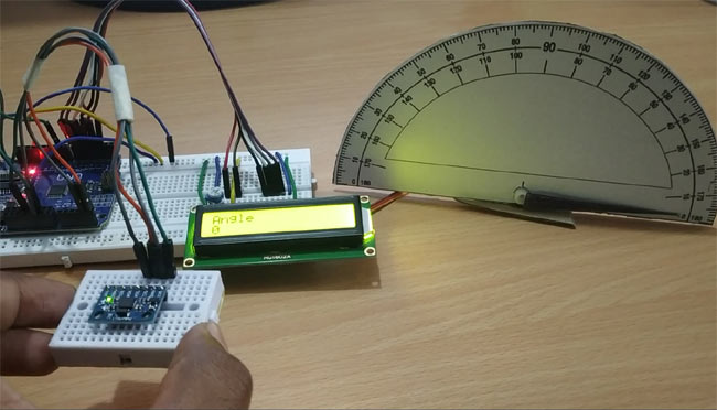
So this is how MPU6050 with Arduino can be used to measure the angle. Complete code and video for this project is given below.
Complete Project Code
#include <Servo.h>                 //Include Servo Motor library for using Servo
#include <LiquidCrystal.h>         //Include LCD library for using LCD
#include <Wire.h>                  //Include WIre library for using I2C
LiquidCrystal lcd(2,3,4,5,6,7);   //Define LCD display pins RS,E,D4,D5,D6,D7
const int MPU_addr=0x68;         //I2C MPU6050 Address
Servo myservo;                  //myservo object for class servo
int16_t axis_X,axis_Y,axis_Z;
int minVal=265;
int maxVal=402;
double x;
double y;
double z;
int pos = 0;
void setup()
{
  Wire.begin();                        //Begins I2C communication
  Wire.beginTransmission(MPU_addr);    //Begins Transmission with MPU6050
  Wire.write(0x6B);                    //Puts MPU6050 in Sleep Mode
  Wire.write(0);                       //Puts MPU6050 in power mode
  Wire.endTransmission(true);          //Ends Trasmission

  myservo.attach(9);               //Servo PWM pin as 9 in UNO
  lcd.begin(16,2);                 //Sets LCD in 16X2 Mode
  lcd.print("CIRCUIT DIGEST");
  delay(1000);
  lcd.clear();
  lcd.setCursor(0,0);
  lcd.print("Arduino");
  lcd.setCursor(0,1);
  lcd.print("MPU6050");
  delay(2000);
  lcd.clear();
}
void loop()
{
  Wire.beginTransmission(MPU_addr); //Begins I2C transmission
  Wire.write(0x3B);                 //Start with register 0x3B (ACCEL_XOUT_H)
  Wire.endTransmission(false);
  Wire.requestFrom(MPU_addr,14,true); //Request 14 Registers from MPU6050

  axis_X=Wire.read()<<8|Wire.read(); //Obtain 0x3B (ACCEL_XOUT_H) & 0x3C (ACCEL_XOUT_L)
  axis_Y=Wire.read()<<8|Wire.read(); //0x3B (ACCEL_YOUT_H) & 0x3C (ACCEL_YOUT_L)
  axis_Z=Wire.read()<<8|Wire.read(); //0x3B (ACCEL_ZOUT_H) & 0x3C (ACCEL_ZOUT_L)

    int xAng = map(axis_X,minVal,maxVal,-90,90);
    int yAng = map(axis_Y,minVal,maxVal,-90,90);
    int zAng = map(axis_Z,minVal,maxVal,-90,90);
   x= RAD_TO_DEG * (atan2(-yAng, -zAng)+PI);     //Formula to calculate x values in degree
     int pos = map(x,0,180,0,180); // As X value is from 0 to 360 deg
     myservo.write(pos);           // Write angle obtained 0 to 180 to servo
     lcd.setCursor(0,0);
     lcd.print("Angle");
     lcd.setCursor(0,1);
     lcd.print(x);
     delay(500);
     lcd.clear();
}

Awesome project Pramoth! I didn't understand the part "Next minimum and maximum value is set as 265 and 402 for measuring angle from 0 to 360" though. Could you explain how setting the minimum and maximum values to 265 and 402 correspond to a measuring angle from 0 to 360 degrees?