

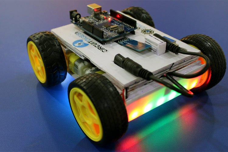
For many years, robots have been a popular topic among students, hobbits, and DIYers. If you are a beginner and enjoy building robots, this is likely the first project you will do after learning the basics, which is why we decided to build a Wireless Bluetooth Controlled Robot Car Using Arduino. This robot car can be controlled wirelessly with Bluetooth and an android app, and other than that we have placed RGB Neopixel LEDs on the front, back, and bottom of the robot to make it look cool. We will also build a custom android app with the MIT app inventor so that we can send commands directly via Bluetooth and control the robot's movements and also control the LEDs on the robot. You can check out the video given at the bottom of this page for complete build details.
Previously we made some other robotic projects, if you want to build something different and easier you can check out our other projects linked down below.
Automatic Surface Disinfecting Robot using Ultraviolet Lights
DIY Smart Vacuum Cleaning Robot using Arduino
WiFi Controlled Robot using Arduino
Build a Simple Arduino RC Boat that can be Controlled Wirelessly using 433 MHz RF Modules
Components & Tools Required to Build Wireless Arduino Bluetooth Robot
- Arduino UNO *1
- HC05 Module *1
- L298N Motor driver *1
- NeoPixel LED x as required
- Lithium ion 18650 battery with protection circuit *1
- BO Motors with wheels *4
- Perf board big *1
- Perfboard small *1
- Toggle switch *1
- DC female jack *1
- Relimate connector pair *1
- Male bergstrip *1
- Female Bergstip *2
- Single Strand Wires of various colors * as required
- Sunboard of medium thickness * as required
- Paper Cutter, Hot Glue, Feviquick, Ruler, Marker, Wirecutter, Screwdriver
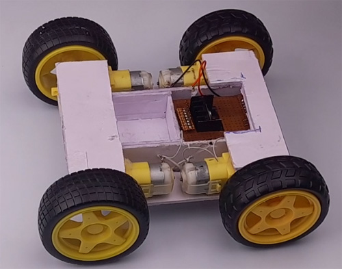
Building the Chassis for Arduino based Bluetooth Robot
Chassis of the Robot is the base/main part of the bot that holds all the circuits of the bot. So, we will be using sunboards to make a reliable and strong chassis.
These boards are equally strong as cardboards but they are lightweight and cost-effective. We will require half of the full sheet for our whole construction.
Note: I recommend cutting extra pieces of the sunboards so that you can replace them easily if they get broken during the building process.
Cut out the pieces of given dimensions:
- Rectangular piece of 10.5 X 13.5 cm (2 pcs)
- Strips of 7.5 X 2.3 cm (2 pcs)
- Strip of 11.5 X 2.3 cm (2 pcs)
- 4.3 X 2.3 cm (1 pc)
- 10.5 X 3.5 cm (2 pcs)
It will look like this-
Connecting Motors
Now all four motors will be connected in such a way that they will be formed into two pairs and each pair will be connected in parallel to each other. Likewise, Right side motors are connected in parallel drive and same with the left one.
Tip: If you connect the motor in the corresponding cross direction then it will be connected in parallel. Please refer to the video for more information.
Attaching motor to the motor driver
Since we are using the L298N Module, we have 2 screw terminals on both sides for connecting the motors. Just randomly attach the motors with the driver as the polarity and direction can be controlled using the input pins attached with the Arduino. This we discuss in upcoming steps.
Motor driver attachment
I have made a separate Hardware attachment for the motor driver that will provide the connections to the Arduino Uno board.
Arduino UNO Protoshield
Since Arduino Protoshield can be used for direct connection of IN1, IN2, IN3, IN4 of the motor diver, and other connections but I had tried to make my own protoshield for the onboard connections. For the connectivity, I have used Female berstrips, male berstrips, and relimate connector onboard.
Arduino Bluetooth Car Circuit Diagram
The complete circuit diagram for the Arduino Bluetooth Car is shown below. This circuit is made out of generic components and can be found in your local store or it's easily available on any online store so the replication process becomes easier.

The working of this circuit is very simple and easy to understand. First, we have the Arduino which is working as the brains of the circuit. Next, we have the Bluetooth module. The Bluetooth module is connected to pin 13 and 10 of the Arduino that we are using as the software serial. Next, we are using pins 11,12,8, and 7 to connect our WS2812B RGB leds. Finally, we are using pins 9, 6, 5and 4 to connect the L298N motor driver IC that is driving four of our motors. Finally, to power it all up, we are using a 9V battery.
|
Arduino |
L298N |
|
3 |
IN1 |
|
9 |
IN2 |
|
5 |
IN3 |
|
6 |
IN4 |
|
VIN |
+5V |
|
GND |
GND |
|
Arduino |
HC05 |
|
10 |
Tx |
|
11 |
Rx |
|
+5V |
VCC |
|
GND |
GND |
|
Arduino |
NeoPixel |
|
8 |
Left LED |
|
7 |
Right LED |
|
12 |
Front LED Data |
|
13 |
Back LED Data |
The working of this circuit is very easy.
Arduino Code for Bluetooth Controlled Robot
The code for the Arduino, and Bluetooth-based robot is a little bit complicated, so we separate the total code into three separate files this way we can change things quickly in the code if needed. We will start with the main file.
arduino_bluetooth_bot_main:
As we all know the Bluetooth module uses serial communication to communicate with the Arduino, and as the Arduino has only one serial port or TX, and RX port we need to use SoftwareSerial.h library of the Arduino to communicate with the Bluetooth module. So in the void setup() function, we begin hardware serial at 9600 baud for debugging and we open software serial at 38400 baud to communicate with the Bluetooth. Then we check if the Bluetooth module is working or not by sending AT command to the Bluetooth module. If the Bluetooth module returns an OK command, then surely the Bluetooth module is working exactly as intended. Once that was done we called LED_setup() function to set up the neo pixel LEDs which we will discuss later.
#include <SoftwareSerial.h>
SoftwareSerial mySerial(10, 11); // RX, TX
void setup() {
  // Open serial communications and wait for port to open:
  Serial.begin(9600);
  mySerial.begin(38400);
  while (!Serial) {
    ; // wait for serial port to connect. Needed for native USB port only
  }
  Serial.println("Sending AT...");
  mySerial.write("AT");
  if (mySerial.available()>0) {
    Serial.write(mySerial.read());
  }
  // set the data rate for the SoftwareSerial port
    Serial.println("loop begins");
     LED_setup();
}
Next, we have to initialize three global variables, the first one is called rcd and it's a character type variable that will hold the received data from the Bluetooth module. Next, we define an integer type variable spd that will hold the speed data of the car. Then we have a long type variable time_now variable which we will be using to hold time data. Now the code is very simple. We check the rcd variable that it is receiving and execute an if condition accordingly. We continue this process for all the RGB LEDs and robot movements. And that marks the end of our loop function.
void loop() { // run over and over
  if (mySerial.available()) {
    rcd = mySerial.read();
    Serial.write(rcd);
  }
  unsigned long time_now = 0;
  if (rcd == 'O')
  {
    R_LED(1);
    L_LED(1);
    F_LED(1);
    B_LED(1);
  }
  if (rcd == 'o')
  {
    R_LED(0);
    L_LED(0);
    F_LED(0);
    B_LED(0);
  }
  if (rcd == 'X')
  { L_LED(1);
  }
  if (rcd == 'x')
  {
    L_LED(0);
  }
  if (rcd == 'P')
  {
    R_LED(1);
  }
  if (rcd == 'p')
  { R_LED(0);
  }
  if (rcd == 'W')
  { F_LED(1);
  }
  if (rcd == 'w')
  { F_LED(0);
  }
  if (rcd == 'U')
  { B_LED(1);
  }
  if (rcd == 'u')
  { B_LED(0);
  }
  if (rcd == '0')
  { spd = 80;
  }
  if (rcd == '1')
  { spd = 100;
  }
  if (rcd == '3')
  { spd = 120;
  }
  if (rcd == '5')
  { spd = 180;
  }
  if (rcd == 'q')
  { spd = 255;
  }
  if (rcd == 'F')
  { Forward();
    time_now = millis();
    while (millis() < time_now + 100) {}
  }
  else if (rcd == 'B')
  { time_now = millis();
    while (millis() < time_now + 100) {}
    Backward();
  }
  else if (rcd == 'I')
  { time_now = millis();
    while (millis() < time_now + 100) {}
    FdRight();
  }
  else if (rcd == 'J')
  { time_now = millis();
    while (millis() < time_now + 100) {}
    BkRight();
  }
  else if (rcd == 'R')
  { time_now = millis();
    while (millis() < time_now + 100) {}
    SharpRight();
  }
  else if (rcd == 'L')
  { time_now = millis();
    while (millis() < time_now + 100) {}
   SharpLeft();
  }
  else if (rcd == 'G')
  { time_now = millis();
    while (millis() < time_now + 100) {}
   FdLeft();
  }
  else if (rcd == 'H')
  { time_now = millis();
    while (millis() < time_now + 100) {}
    BkLeft();
  }
  else
    Stop();
}
led_control:
Inside the led controller file we have set up, declared, and defined the pins where the neopixel LEDs are connected. To control the neopixels we have used the Adafruit_NeoPixel library.
#include <Adafruit_NeoPixel.h>
#ifdef __AVR__
#include <avr/power.h>
#endif
#define F_LED_PIN        12 //Front LED
#define F_LED_PIXEL       6
#define B_LED_PIN        13  //Back LED
#define B_LED_PIXEL       6
#define R_LED_PIN        7 //Right LED
#define R_LED_PIXEL       1
#define L_LED_PIN        8 //Left LED
#define L_LED_PIXEL       1
Adafruit_NeoPixel F_LED_STRIP(F_LED_PIXEL, F_LED_PIN, NEO_GRB + NEO_KHZ800);
Adafruit_NeoPixel B_LED_STRIP(B_LED_PIXEL, B_LED_PIN, NEO_GRB + NEO_KHZ800);
Adafruit_NeoPixel R_LED_STRIP(R_LED_PIXEL, R_LED_PIN, NEO_GRB + NEO_KHZ800);
Adafruit_NeoPixel L_LED_STRIP(L_LED_PIXEL, L_LED_PIN, NEO_GRB + NEO_KHZ800);
Next inside this file, we have LED_setup() function. Inside this function, we have initialized all the neopixels LEDs and cleared them out with the default function provided by Adafruit, so that the neopixels don't light up randomly at the start of the code.
void LED_setup()
{
  #if defined(__AVR_ATtiny85__) && (F_CPU == 16000000)
  clock_prescale_set(clock_div_1);
#endif
  F_LED_STRIP.begin();
  B_LED_STRIP.begin();
  R_LED_STRIP.begin();
  L_LED_STRIP.begin();
  R_LED_STRIP.clear();
  L_LED_STRIP.clear();
  F_LED_STRIP.clear();
  B_LED_STRIP.clear();
}
Next, we have another four functions that control all the LEDs. Those functions are attached to the robot and are called R_LED, L_LED, F_LED, B_LED respectively.
void R_LED(int a)
{
  if(a==1)
  {
    R_LED_STRIP.clear();
    R_LED_STRIP.setPixelColor(0, R_LED_STRIP.Color(0, 255, 255));
   R_LED_STRIP.show();   // Send the updated pixel colors to the hardware.
  }
  else {
    R_LED_STRIP.clear();
     R_LED_STRIP.show();
  }
}
void L_LED(int a)
{
  if(a==1)
  {
    L_LED_STRIP.clear();
    L_LED_STRIP.setPixelColor(0, L_LED_STRIP.Color(0, 255, 255));
   L_LED_STRIP.show();   // Send the updated pixel colors to the hardware.
  }
  else
  {
     L_LED_STRIP.clear();
     L_LED_STRIP.show();
  }
}
void F_LED(int a)
{
  if(a==1)
  {
    F_LED_STRIP.clear();
    F_LED_STRIP.setPixelColor(0, F_LED_STRIP.Color(255, 255, 255));
    F_LED_STRIP.setPixelColor(1, F_LED_STRIP.Color(0, 0, 50));
    F_LED_STRIP.setPixelColor(2, F_LED_STRIP.Color(0, 0, 50));
    F_LED_STRIP.setPixelColor(3, F_LED_STRIP.Color(0, 0, 50));
    F_LED_STRIP.setPixelColor(4, F_LED_STRIP.Color(0, 0, 50));
    F_LED_STRIP.setPixelColor(5, F_LED_STRIP.Color(255, 255, 255));
   F_LED_STRIP.show();   // Send the updated pixel colors to the hardware.
  }
  else if(a==0)
  {
    F_LED_STRIP.clear();
    F_LED_STRIP.show();
  }
}
void B_LED(int a)
{
  if(a==1)
  {
    B_LED_STRIP.clear();
    B_LED_STRIP.setPixelColor(0, B_LED_STRIP.Color(255, 0, 0));
    B_LED_STRIP.setPixelColor(1, B_LED_STRIP.Color(0, 50, 0));
    B_LED_STRIP.setPixelColor(2, B_LED_STRIP.Color(0, 50, 0));
    B_LED_STRIP.setPixelColor(3, B_LED_STRIP.Color(0, 50, 0));
    B_LED_STRIP.setPixelColor(4, B_LED_STRIP.Color(0, 50, 0));
    B_LED_STRIP.setPixelColor(5, B_LED_STRIP.Color(255, 0, 0));
    B_LED_STRIP.show();   // Send the updated pixel colors to the hardware.
  }
  else if(a==0)
  {
    B_LED_STRIP.clear();
    B_LED_STRIP.show();
  }
}
This marks the end of the led_control code portion.
Movements :
Next, we have our movement files. In this particular file, we have defined functions to control the movement of the robot. In the function shown below, we have used analogWrite(5, spd) function and passed the pin and speed value so that it can generate a PWM signal. After that we are driving a motor driver IC and that in turn drives the motor.
void Forward()
{
  analogWrite(5, spd);
  digitalWrite(6, 0);
  analogWrite(9, spd);
  digitalWrite(3, 0);
  //  delay(50);
}
void Backward()
{
  digitalWrite(5, 0);
  analogWrite(6, spd);
  digitalWrite(9, 0);
  analogWrite(3, spd);
}
void Stop()
{
  analogWrite(5, 0);
  digitalWrite(6, 0);
  analogWrite(9, 0);
  digitalWrite(3, 0);
}
void FdRight()
{
  analogWrite(5, spd);
  digitalWrite(6, 0);
  digitalWrite(9, 0);
  analogWrite(3, 0);
}
void BkRight()
{
  analogWrite(5, 0);
  digitalWrite(6, 0);
  digitalWrite(9, 0);
  analogWrite(3, spd);
}
void SharpRight()
{
  analogWrite(5, spd);
  digitalWrite(6, 0);
  digitalWrite(9, 0);
  analogWrite(3, spd);
}
void SharpLeft()
{
  digitalWrite(5, 0);
  analogWrite(6, spd);
  analogWrite(9, spd);
  digitalWrite(3, 0);
}
void BkLeft()
{
  digitalWrite(5, 0);
  analogWrite(6, spd);
  analogWrite(9, 0);
  digitalWrite(3, 0);
}
void FdLeft()
{
  digitalWrite(5, 0);
  analogWrite(6, 0);
  analogWrite(9, spd);
  digitalWrite(3, 0);
}
That's all there is for the code part and we can move on to the android app part.
Building the Android App for our Bluetooth Controlled Robot
Building the android application was very simple with the app inventor. First, we started by designing the user interface. As you can see on the left-hand side of the image the screenshot is taken from the web GUI of the MIT app inventor and the right-hand side of the image is a screenshot from the phone. Once we were satisfied with the GUI, we proceeded with the logical part of the app.
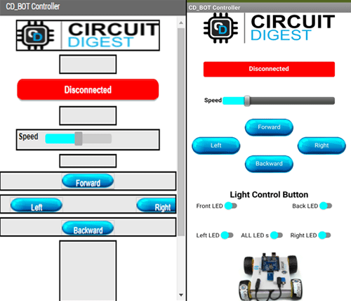
In the logical part, there is nothing much. We use standard app inventor methods to connect to the HC-05 Bluetooth and once the connection is done, we just send some specific commands to move the robot and control the LEDs in the robot. The aia file for the android app is given, you can download and edit it to your heart's content. Screenshot of the MIT app inventor logical part is given below-

That concludes the app-building process.

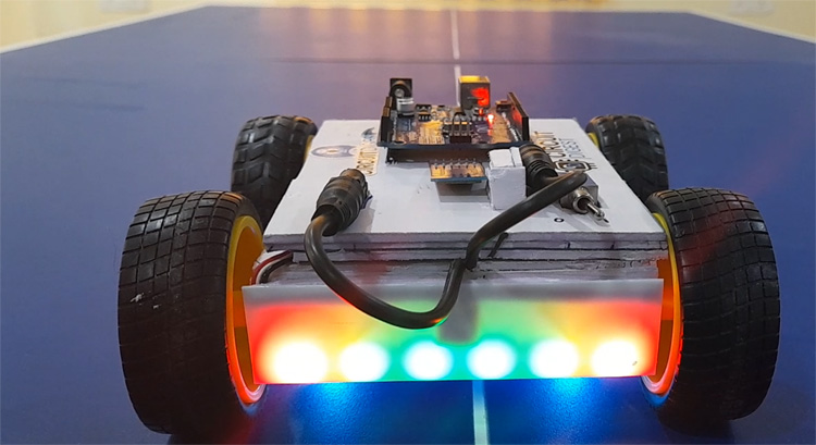
Bluetooth Controlled Robot - In action
For the testing part, we made the circuit beforehand and tested every part differently, so we can determine any faults in our part. Once every part was tested, we started to build the robot by first measuring and then cutting the sunboard according to the dimension. Once everything was finished the bot looks something like the image below.
With this, we are concluding our project Arduino-based android and Bluetooth controlled robot car. Hope you have enjoyed reading this and learned something useful. Now it’s time for you to build it on your own and let us know what you are doing with this project in the comment section below. If you have any questions, you can use our forum to get in touch with us.
Complete Project Code
Arduino_Bluetooth_Bot_main
#include <SoftwareSerial.h>
SoftwareSerial mySerial(10, 11); // RX, TX
void setup() {
  // Open serial communications and wait for port to open:
  Serial.begin(9600);
  mySerial.begin(38400);
  while (!Serial) {
    ; // wait for serial port to connect. Needed for native USB port only
  }
  Serial.println("Sending AT...");
  mySerial.write("AT");
  if (mySerial.available() > 0) {
    Serial.write(mySerial.read());
  }
  // set the data rate for the SoftwareSerial port
  Serial.println("loop begins");
  LED_setup();
}
char rcd = ' ';
int spd = 100;
unsigned long time_now = 0;
void loop() { // run over and over
  if (mySerial.available()) {
    rcd = mySerial.read();
    Serial.write(rcd);
  }
  unsigned long time_now = 0;
  if (rcd == 'O')
  {
    R_LED(1);
    L_LED(1);
    F_LED(1);
    B_LED(1);
  }
  if (rcd == 'o')
  {
    R_LED(0);
    L_LED(0);
    F_LED(0);
    B_LED(0);
  }
  if (rcd == 'X')
  { L_LED(1);
  }
  if (rcd == 'x')
  {
    L_LED(0);
  }
  if (rcd == 'P')
  {
    R_LED(1);
  }
  if (rcd == 'p')
  { R_LED(0);
  }
  if (rcd == 'W')
  { F_LED(1);
  }
  if (rcd == 'w')
  { F_LED(0);
  }
  if (rcd == 'U')
  { B_LED(1);
  }
  if (rcd == 'u')
  { B_LED(0);
  }
  if (rcd == '0')
  { spd = 80;
  }
  if (rcd == '1')
  { spd = 100;
  }
  if (rcd == '3')
  { spd = 120;
  }
  if (rcd == '5')
  { spd = 180;
  }
  if (rcd == 'q')
  { spd = 255;
  }
  if (rcd == 'F')
  { Forward();
    time_now = millis();
    while (millis() < time_now + 100) {}
  }
  else if (rcd == 'B')
  { time_now = millis();
    while (millis() < time_now + 100) {}
    Backward();
  }
  else if (rcd == 'I')
  { time_now = millis();
    while (millis() < time_now + 100) {}
    FdRight();
  }
  else if (rcd == 'J')
  { time_now = millis();
    while (millis() < time_now + 100) {}
    BkRight();
  }
  else if (rcd == 'R')
  { time_now = millis();
    while (millis() < time_now + 100) {}
    SharpRight();
  }
  else if (rcd == 'L')
  { time_now = millis();
    while (millis() < time_now + 100) {}
    SharpLeft();
  }
  else if (rcd == 'G')
  { time_now = millis();
    while (millis() < time_now + 100) {}
    FdLeft();
  }
  else if (rcd == 'H')
  { time_now = millis();
    while (millis() < time_now + 100) {}
    BkLeft();
  }
  else
    Stop();
}

LED_Control
#include <Adafruit_NeoPixel.h>
#ifdef __AVR__
#include <avr/power.h>
#endif
#define F_LED_PIN        12 //Front LED
#define F_LED_PIXEL       6
#define B_LED_PIN        13  //Back LED
#define B_LED_PIXEL       6
#define R_LED_PIN        7 //Right LED
#define R_LED_PIXEL       1
#define L_LED_PIN        8 //Left LED
#define L_LED_PIXEL       1
Adafruit_NeoPixel F_LED_STRIP(F_LED_PIXEL, F_LED_PIN, NEO_GRB + NEO_KHZ800);
Adafruit_NeoPixel B_LED_STRIP(B_LED_PIXEL, B_LED_PIN, NEO_GRB + NEO_KHZ800);
Adafruit_NeoPixel R_LED_STRIP(R_LED_PIXEL, R_LED_PIN, NEO_GRB + NEO_KHZ800);
Adafruit_NeoPixel L_LED_STRIP(L_LED_PIXEL, L_LED_PIN, NEO_GRB + NEO_KHZ800);
void LED_setup()
{
  #if defined(__AVR_ATtiny85__) && (F_CPU == 16000000)
  clock_prescale_set(clock_div_1);
#endif
  F_LED_STRIP.begin();
  B_LED_STRIP.begin();
  R_LED_STRIP.begin();
  L_LED_STRIP.begin();
  R_LED_STRIP.clear();
  L_LED_STRIP.clear();
  F_LED_STRIP.clear();
  B_LED_STRIP.clear();
}
void R_LED(int a)
{
  if(a==1)
  {
    R_LED_STRIP.clear();
    R_LED_STRIP.setPixelColor(0, R_LED_STRIP.Color(0, 255, 255));
   R_LED_STRIP.show();   // Send the updated pixel colors to the hardware.
  }
  else {
    R_LED_STRIP.clear();
     R_LED_STRIP.show();
  }
}
void L_LED(int a)
{
  if(a==1)
  {
    L_LED_STRIP.clear();
    L_LED_STRIP.setPixelColor(0, L_LED_STRIP.Color(0, 255, 255));
   L_LED_STRIP.show();   // Send the updated pixel colors to the hardware.
  }
  else
  {
     L_LED_STRIP.clear();
     L_LED_STRIP.show();
  }
}
void F_LED(int a)
{
  if(a==1)
  {
    F_LED_STRIP.clear();
    F_LED_STRIP.setPixelColor(0, F_LED_STRIP.Color(255, 255, 255));
    F_LED_STRIP.setPixelColor(1, F_LED_STRIP.Color(0, 0, 50));
    F_LED_STRIP.setPixelColor(2, F_LED_STRIP.Color(0, 0, 50));
    F_LED_STRIP.setPixelColor(3, F_LED_STRIP.Color(0, 0, 50));
    F_LED_STRIP.setPixelColor(4, F_LED_STRIP.Color(0, 0, 50));
    F_LED_STRIP.setPixelColor(5, F_LED_STRIP.Color(255, 255, 255));
   F_LED_STRIP.show();   // Send the updated pixel colors to the hardware.
  }
  else if(a==0)
  {
    F_LED_STRIP.clear();
    F_LED_STRIP.show();
  }
}
void B_LED(int a)
{
  if(a==1)
  {
    B_LED_STRIP.clear();
    B_LED_STRIP.setPixelColor(0, B_LED_STRIP.Color(255, 0, 0));
    B_LED_STRIP.setPixelColor(1, B_LED_STRIP.Color(0, 50, 0));
    B_LED_STRIP.setPixelColor(2, B_LED_STRIP.Color(0, 50, 0));
    B_LED_STRIP.setPixelColor(3, B_LED_STRIP.Color(0, 50, 0));
    B_LED_STRIP.setPixelColor(4, B_LED_STRIP.Color(0, 50, 0));
    B_LED_STRIP.setPixelColor(5, B_LED_STRIP.Color(255, 0, 0));
    B_LED_STRIP.show();   // Send the updated pixel colors to the hardware.
  }
  else if(a==0)
  {
    B_LED_STRIP.clear();
    B_LED_STRIP.show();
  }
}

Movements
void Forward()
{
  analogWrite(5, spd);
  digitalWrite(6, 0);
  analogWrite(9, spd);
  digitalWrite(3, 0);
  //  delay(50);
}
void Backward()
{
  digitalWrite(5, 0);
  analogWrite(6, spd);
  digitalWrite(9, 0);
  analogWrite(3, spd);
}
void Stop()
{
  analogWrite(5, 0);
  digitalWrite(6, 0);
  analogWrite(9, 0);
  digitalWrite(3, 0);
}
void FdRight()
{
  analogWrite(5, spd);
  digitalWrite(6, 0);
  digitalWrite(9, 0);
  analogWrite(3, 0);
}
void BkRight()
{
  analogWrite(5, 0);
  digitalWrite(6, 0);
  digitalWrite(9, 0);
  analogWrite(3, spd);
}
void SharpRight()
{
  analogWrite(5, spd);
  digitalWrite(6, 0);
  digitalWrite(9, 0);
  analogWrite(3, spd);
}
void SharpLeft()
{
  digitalWrite(5, 0);
  analogWrite(6, spd);
  analogWrite(9, spd);
  digitalWrite(3, 0);
}
void BkLeft()
{
  digitalWrite(5, 0);
  analogWrite(6, spd);
  analogWrite(9, 0);
  digitalWrite(3, 0);
}
void FdLeft()
{
  digitalWrite(5, 0);
  analogWrite(6, 0);
  analogWrite(9, spd);
  digitalWrite(3, 0);
}
Comments
hello, the MIT app…
hello,
the MIT app inventor app does not exist in the link provided above , please help me to find the file to complete this project.
best regards
Hi, you can download the MIT…
Hi, you can download the MIT app inventor file from the Building the Android App for our Bluetooth Controlled Robot section in the above article. The link is checked and verified to be working.

Hello,
I have designed the RC car as per the description also downloaded the app code compiled it with MIT inventor. installed app , LED is blowing in aurdino as well as in bluetooth. but car is not responding as per the back and forth button pressed from the app. Please do needful.
Thank you