

The TDA7294 IC is a popular sound amplifier IC with low cost that has a ton of power handling capacity, 100W to be exact. For this tutorial, we are going to use two of those TDA7294 ICs in a bridge configuration to build an even more powerful amp that can handle up to 170W of RMS power. Throughout this tutorial we will walk you through the building process and first, we will show you how you can calculate the voltage and current that is required for your power supply, then we will find how to get a proper heatsink as per the thermal data given in the datasheet of the TDA7294 IC and finally, we will discuss how you can change the gain of the amplifier by tweaking the values of the circuit a little. So, without further ado, let’s get right into it.
Also, check our other Audio Amplifier Circuits where we have built 25w, 40w, 100w audio amplifier circuits using op-amps, MOSFETs, and IC like TDA2030, TDA2040, and TDA2050.
Important Parameters to Consider Before we Start
Before we begin, it’s a good idea to consider how much output power we want from the amplifier, as we have discussed earlier it would be around 150W to 170W RMS power, you should also know the impedance of the speaker and the input voltage of the audio source that you can find in the datasheet of TDA7294 IC. In this configuration, the load must not be lower than 8 Ω for dissipation and current capability reasons. The TDA7294 IC can output 170W of power in a 16 Ω speaker with 0.5% distortion on a ± 35V power supply. For the audio source, we'll be using a smartphone that can easily produce the 500-900mV peak power output.
Choosing an Adequate Power Supply for the Project and Calculation
The TDA7294 IC can be powered from a dual or split power supply, in this way the performance and the efficiency of the device increase greatly. That's why we'll be using a split power supply rather than a single one. The goal here is to find the right transformer, which can provide sufficient voltage and current to drive the amplifier properly.
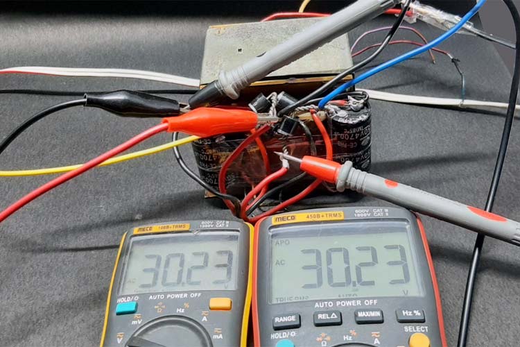
If we consider the 30-0-30 transformer shown above, it will output more or less 30-0-30V AC if the input supply voltage is 230V. But as AC mains input always drifts, the output will also drift. Taking that fact into consideration, now we can calculate the supply voltage for the amplifier. The transformer gives us AC voltage and if we convert that into DC voltage, we will get
VsupplyDC = 30*(1.41) = 42.3VDC
This value is a little bit more than what we were targeting initially but it is within the absolute maximum rating of the device according to the datasheet. It can be clearly stated that the transformer can deliver 42.3VDC when the input is 230V AC. Now if we consider voltage drift of 5%, we can see that the maximum output voltage becomes
VmaxDC = (42.3 +2.4) = 44.77V
Which is well within the maximum supply voltage range of the TDA7294 IC.
Thermal Requirements (Finding a Suitable Heat Sink)
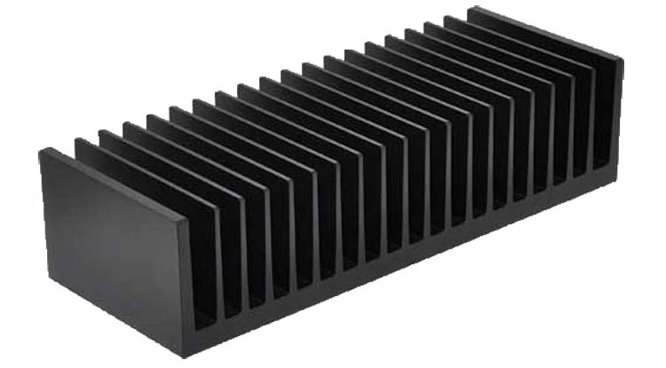
Now that we have calculated the maximum power requirements, we can turn our focus into finding out a suitable heatsink for our amp circuit. For this build, I have chosen an aluminum, extrusion-type heat sink. Aluminum is a well-known substance for heat-sink because it's relatively inexpensive and exhibits good thermal performance. To verify the maximum junction temperature of the TDA7294 IC, we can use the popular thermal equations, which you can find in this Wikipedia link.
We use the general principle that the temperature drop ΔT across a given absolute thermal resistance RØ with a given heat flow Q through it. And the final formula would be,
Qmax = (TJmax – (Tamb + ΔTHS)) / (RØJC + RØB + RØHA)
TJmax = 150 °C (typical for a silicon device)
Tamb = 29 °C (room temperature)
RØJC = 1.5 °C/W (for a typical TO-220 package)
RØB = 0.1 °C/W (typical value for an elastomer heat transfer pad for a TO-220 package)
RØHA = 2 °C/W
So, the final result becomes
Q = (150 - 29) / (1.5+0.1+2) = 15.14W
This means we have to dissipate 15.14 watts or more to prevent the device from overheating and getting damaged.
Note: Please note that at the time of making this project I didn't have any other big heat sink in my stockpile so I had to use the biggest one I have, for a smooth operation a bigger heat sink is recommended.
TDA7294 Based Amplifier Circuit Diagram
The circuit diagram for the TDA7294 amplifier circuit is given below:

Components Required to Build TDA7294 Based Amplifier Circuit
This circuit is very easy to replicate because we used generic components to build it, you can find the pars requirements for this project in this section.
- TDA7294 IC - 2
- Screw Terminal 2.54 mm - 2
- Screw Terminal 5mm - 1
- 22k Ohms Resistor - 5
- 680 Ohm Resistor - 2
- 33k Ohm Resistor - 1
- 10k Ohm Resistor - 1
- 0.56uF Capacitor - 2
- 22µF Capacitor - 4
- Clad Board 50x 50mm - 1
- 6Amp Diode - 4
- 2200µF Capacitor - 2
- 0.22uF Capacitor - 2
- Heat Sink - 1

Detailed Explanation of TDA7294 Based Amplifier Circuit
Now as we have seen the complete schematic of the circuit, we can understand how the circuit works. We will start off with setting the gain of the amplifier as it’s the most important part.
Setting Gain for Amplifier
Setting up the gain for the amplifier is the most important step of the build, as a low gain setting may not provide enough power. And a high gain setting will certainly distort the amplified output signal of the circuit. With my experience, I can tell that setting the gain in between 30 to 35 dB is good for playing audio with a smartphone or a USB audio kit. That is why we are going to focus on that.
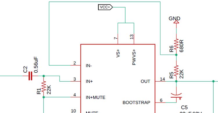
In the above circuit, the output from pin 14 is fed back to pin 2 with a voltage divider configuration
Note: For setting up the amplifiers gain 1% or 0.5%, resistors must be used otherwise the stereo channels will produce different outputs.
Setting Input Filter for Amplifier
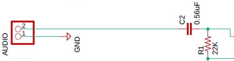
The Resistor R1 in conjunction with C2 acts as a high pass filter that determines the lower end of the bandwidth. Other than that, the capacitor C2 acts as a DC blocking capacitor.
The cut-off frequency of the amplifier can be found by using the following formula shown below.
FC = 1 / (2πRC)
Where R and C are the values of the components.
To find the values of C, we have to rearrange the equation to:
C = 1 / (2π x 22000R x 3.5Hz) = 4.7uF
Note: It is recommended to use metal film oil capacitors for the best audio performance.
Setting Output and Configuring the Bootstrap
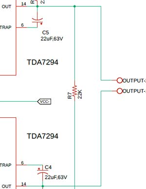
Next, we will set the output by configuring the bootstrap pin of the TDA7294 IC.
As you can clearly see that pin 6 of the IC is the bootstrap pin of the amplifier, which needs to be connected to the output pin (pin 14) of the IC and that's how this IC will get to know that it is configured in a bootstrap configuration.
Single Signal ST-BY/MUTE Control Circuit
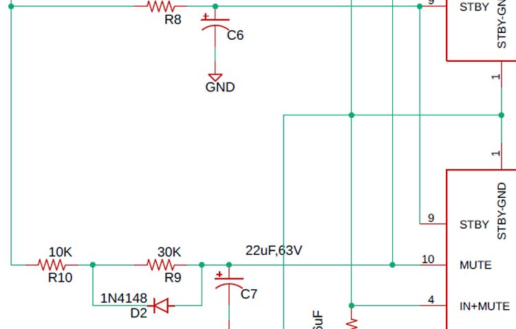
The above figure shows the possibility of using only one command for both st-by and mute functions. On both the pins, the maximum applicable range corresponds to the operating supply voltage which means by applying a range of input voltage this device can be put to standby or Mute mode.
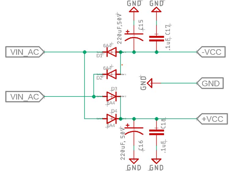
Power Supply for Amplifier
A dual polarity power supply with proper decoupling capacitors is required to power the amplifier, and the schematic is shown below. Though the power supply section is not a part of the schematic, we are going to use this bridge rectifier configuration to power the circuit.
Circuit Construction
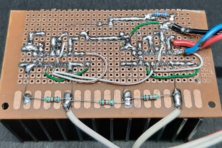
For the demonstration, the circuit is constructed on a handmade dotted perf board with the help of schematic. Please note that if we are connecting a big load to the output of the amplifier, a huge amount of current will flow through, and to overcome that we have used a single strand of CAT6 cable to connect the power line in the perf board.
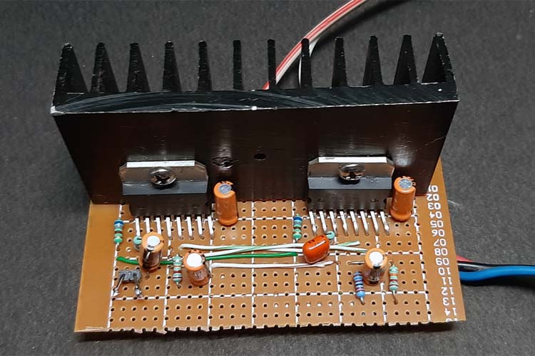
In order to make the circuit a little bit smaller and reduce complexity, I soldered some of the resistors to the backside of the perf board as shown in the below image.
Testing of TDA7294 Amplifier Circuit
The testing process will be very simple, we will connect the power supply and a load to the amplifier. Also, we will connect a temperature sensor with the amplifier to monitor the temperature and we will let it run.
To test the circuit, the following apparatus was used.
- A transformer which has a 30-0-30 Tap
- A 16Ω 180W speaker system as a load
- Meco 108B+TRMS Multimeter as the temperature sensor
- And my Samsung phone as an audio source
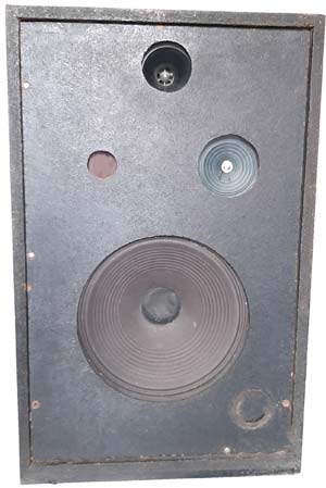
The Speaker System used is shown below. As mentioned earlier this is a 180 Watt speaker system with a 150 Watt RMS main speaker, a 15Watt tweeter for treble, and another 10 Watt of speaker to output the vocal.
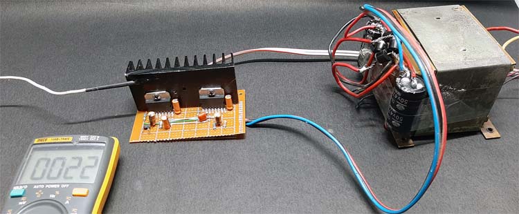
Also, you can see the room temperature was 22°C during the time of testing. At this moment, the amplifier was in an off state and the Multimeter was just showing the room temperature. Generally, the audio output of this amplifier is very good and can be improved by adding an Audio Tone Control Circuit alongside it.
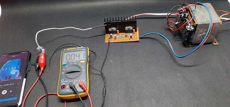
You can see from the above image; the results were more or less great and the temperature of the IC didn't go beyond 41 °C during the testing. After using it for an hour the temperature did not move over 55°C.
This is how you can design a TDA7294 based High Power Audio Amplifier. If you have any questions, please leave them in the comment section below or use our forum to start a discussion on this.
Comments
Hi and good day I have…
Hi and good day
I have build this circuit but it is not working
All resistor and capacitor values were double checked
Supply is symmetrical
The problem is that at low volume the circuit is operating fine but the moment i push up the volume the left hand side IC gets extremley hot and it sound like the circuit starts to clip and muting itself
Even if i push up the bass at low volume it does the same
Voltage levels remain at about +34 0 -34 VDC
I have build 2 of them and the other one does exactly the same as the first one
What could be the cause of this
Kind Regards
Hi,my greetings out there…
Hi,my greetings out there,its nice to be part of this,would you mind if I ask a little bit of technical advise,
I have finish assemble tda7294 ,its both working but the problem is on the right channel there is a hum,all connection are in the right position,whats use to be the problem?
I'll appreciate any advise you will give,thanks in advance.
One thing i have noticed…
One thing i have noticed that on my supply is on the negative rail that the ac ripple is higher and varies a bit
Positive side about 6mv ac and Negative side 150mv
I do not have access to a ossciliscope
Any thoughts on how to reduce this please
I have also tried to built…
I have also tried to built stereo bridge board with TDA 7294, but all four ic's are showing continuity with each other from the body case. Can anyone pls help me out rectifying this...
Regards

projeto bem pratico com esse tda vou desenvolver esse projeto e por em pratica