

Well, IoT is trending everywhere and is one of the greatest things that can be used to make life easier. There are many IoT based home automation projects available on the internet but none of them provides you an option to control the speed of fan over the internet. So here, in this project, we’ll be making an IoT fan speed control circuit to control the speed of a regular fan or other appliances using Blynk. This circuit differs from others in two ways firstly, it is a TRIAC based control and secondly, it is very easy to install. We have designed the complete system to fit into a compact enclosure making it easy to install and mount it with your ceiling or wall fan. This compact design was made possible by the PCB boards fabricated by PCBWay, we will also show you how the board was designed and ordered from PCBway. So, let's take a look at the project plan and build a well-crafted IoT based fan regulator.
We also build a modular home automation system that can convert your ordinary ceiling fan into smart fan that can be controlled via smartphone.
Components Required for Building the IoT Based Fan Speed Controller
Here, we will use a low-cost IoT based control system that will be useful for the following applications:
- Simple products that will take AC input and control Output.
- Act just like a series device between appliances
- Ready to go without any modifications.
- Use an internet connection and connect to the nearby Wi-Fi network to get internet connectivity.
- Use Mobile application (not custom but readymade tool).
- Control up to 250 Watt of appliances on a single go and without much modifications.
- Have a Buzzer that will notify the user when any changes in the state are happening.
To deliver the above project requirements following components are needed:
|
Qty |
Value |
Device |
Package |
Parts |
|
2 |
Screw Terminal 3.5mm Pitch |
Connector |
W237-132 |
X1, X2 |
|
1 |
*DNP* - Short this |
Jumper |
0805 |
R3 |
|
1 |
0.1uF / 400VAC / Polyester Film |
Capacitor |
C150-054X183 |
C2 |
|
1 |
0.1uF / 6.3V |
Capacitor |
0603 |
C4 |
|
2 |
0.1uF / 6.3V |
Capacitor |
0805 |
C1, C7 |
|
1 |
100R |
Resistor - TH - 0.25W |
0309/10 |
R6 |
|
1 |
100R |
Resistor |
0603 |
R5 |
|
1 |
10K |
Resistor |
0805 |
R23, R17 |
|
1 |
10nF 400V |
Capacitor |
C075-052X106 |
C3 |
|
1 |
10uF / 6.3V |
Capacitor |
0805 |
C8 |
|
5 |
12k |
Resistor |
0805 |
R18, R19, R20, R21, R22 |
|
1 |
1K |
Resistor |
0805 |
R25, R4 |
|
1 |
2.2uF / 6.3V |
Capacitor |
0805 |
C6 |
|
1 |
220uF 12v |
Capacitor |
E2,5-7 |
C15 |
|
1 |
2N7002 |
MOSFET |
SOT23 |
Q2 |
|
1 |
4.7mH 0.4A |
EMI Choke |
U9.8 |
L4 |
|
2 |
47k |
Resistor |
0805 |
R1, R2 |
|
1 |
56R |
Resistor-TH-0.25W |
0309/10 |
R7 |
|
1 |
56R/2W |
Resistor - TH - 2W |
0309/10 |
R12 |
|
1 |
AMS1117-3.3V |
Regulator - 3.3V |
SOT229P700X180-4N |
U2 |
|
1 |
BC847ALT1SMD |
Transistor |
SOT23 |
Q1 |
|
1 |
BT136 |
TRIAC |
TO220CS |
T1 |
|
1 |
ESP-12E/F |
WiFi driver & MCU |
ESP-12E |
IC1 |
|
1 |
HLK-5M05 |
SMPS Module |
CONV_HLK-5M05 |
PS1 |
|
1 |
MB10S |
Diode Bridge |
SOIC-4 |
B1 |
|
1 |
MOC3021M |
TRIAC Driver |
DIL06 |
OK1 |
|
1 |
PC817 |
Opto-Coupler |
DIL04 |
OK2 |
|
1 |
Buzzer |
Buzzer |
12mm Round |
LS1 |
|
1 |
PCB |
PCB |
2 - Layer - 70um |
|
|
1 |
Enclosure |
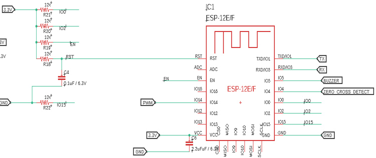
IoT Based Fan Speed Controller Schematic Diagram
The complete circuit diagram for IoT based Fan controller is given below:

Well, the working of the circuit is not so complex and is pretty straightforward. The circuit consists of the following things:
- AC to DC Converter
- Zero crossing circuit
- TRIAC and the Driving circuit
- Buzzer
- Microcontroller
AC to DC Converter:
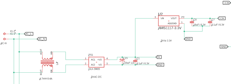
Two voltage levels are required to run the circuit. Here, PS1 is the power supply unit that is converting AC to 5V 1A, which is used for circuit-level operation. However, since we are using ESP12F, we require 3.3V to run the microcontroller unit. The Hi-Link 5V 1A module is used to convert AC 230V mains to the DC 5V 1A. This is further converted to the required 3.3V for the microcontroller using the AMS1117-3.3V LDO regulator U2.
The purpose of L4 is to reduce the common-mode EMI to be entered in the SMPS module. If you are new to EMI, you can check out the article on basics of Electromagnetic Interference and also the Design Techniques for Reducing EMI in SMPS.
Zero-Crossing Circuit:
A zero-crossing circuit is used to detect the time or event whenever the sinusoidal wave crosses the zero region. But why should we do it? Its because we have to switch (increase/decrease) this AC voltage to control the speed of our fan. The best time to start switching an AC wave is when it is crossing the zero point. For beginners, this might be confusing so, please go through the zero-crossing tutorial to understand the basics.
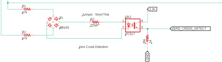
In this circuit, the diode bridge converts the AC sinusoidal wave to an equivalent pulse that will occur 100 times in a second. Because a 50 Hz sinusoidal wave crosses the zero 100 times in a second, which is further converted to a 3.3V logic level using the optocoupler. The optocoupler is used for two reasons. First is to convert the high voltage DC to a low voltage logic level and the other reason is to isolate the high voltage line from the low voltage microcontroller section. The two resistors, R1 and R2 are used to limit the Optocoupler LED current.
TRIAC and the Driving Circuit:
TRIAC is a bidirectional device that conducts current on both sides of the Terminals. The bidirectional feature of TRIACs is very useful for controlling alternating-current (AC) operated devices. Therefore, by using AC Phase Angle Control on a TRIAC, we can control the average current flowing into a load. Thus, detecting the zero crossing, if we turn on the TRIAC with some delay, the load current can be controlled. Here, we are detecting the zero-crossing and turning on the TRIAC with some delay and controlling the current flowing to the fan.
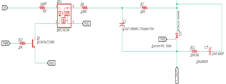
Since FAN is an inductive load, the RC Snubber circuit R12 and C3 are used to protect the TRIAC from generating the back EMF. The resistor R6 and R7 are used to control the trigger current of the TRIAC.
However, the TRIAC can be BTA16 or BT136. Both are suitable. Here we are using BT136 which has 4A of maximum terminal current. The gate threshold voltage of the BT136 is also very less so, can also be driven by digital circuits.
The BC847 is the transistor that conducts the MOC3021 and TRIAC based Opto Isolator which is used to turn on the TRIAC.
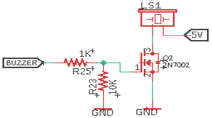
Buzzer Circuit:
The Buzzer circuit is a standard round buzzer that is controlled using a MOSFET 2N7002.
Microcontroller:
The Microcontroller that is used for this project is the widely popular ESP12. It has Wi-Fi and is very cheap as well. The required Pull-up circuits are given for proper working of the module.
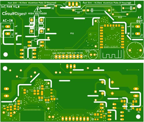
Fabricating PCB for IoT Fan Controller Circuit
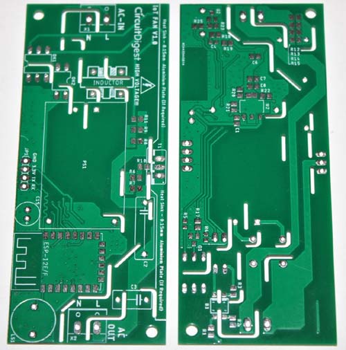
The PCB is designed with proper isolation from AC to DC voltage. However, this is the updated PCB from the one that is used for testing purposes. Few components are made through holes to compensate for the clearance issue rather than the SMD small footprint components. Also, the Boot and RST pin section is given to connect buttons that will be useful during programming purposes. Below are the 3D model views of the top layer and bottom layer of the PCB:
The PCB layout for the above circuit is also available for download as Gerber from the link given below:
Ordering PCB from PCBWay
Now, after finalizing the design, you can proceed with ordering the PCB:
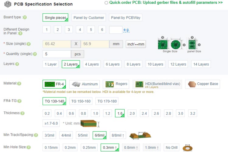
Step 1: Get into https://www.pcbway.com/, sign up if this is your first time. Then, in the PCB Prototype tab, enter the dimensions of your PCB, the number of layers, and the number of PCB you require.

Step 2: Proceed by clicking on the ‘Quote Now’ button. You will be taken to a page to set a few additional parameters like the Board type, Layers, Material for PCB, Thickness, and More, most of them are selected by default, if you are opting for any specific parameters, you can select it here.
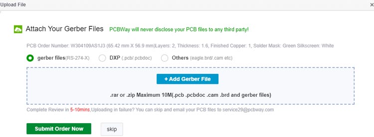
Step 3: The final step is to upload the Gerber file and proceed with the payment. To make sure the process is smooth, PCBWAY verifies if your Gerber file is valid before proceeding with the payment. This way, you can be sure that your PCB is fabrication friendly and will reach you as committed.
Assembling the Fan Controller PCB
After the board was ordered, it reached me after some days through courier in a neatly labeled well-packed box. The PCB quality was good as always. The top layer and the bottom layer of the board are shown below:
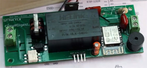
After making sure the tracks and footprints were correct. I proceeded with the assembling of PCB. The completely soldered board looks like the below:

Configuring Blynk to Control Fan Speed
Now that we have the PCB assembled, we can proceed with configuring the Blynk app and programming the ESP. For those who don’t know Blynk is an application that can run over Android and iOS devices to control any IoT devices and appliances using smartphones. First of all, a Graphical User Interface (GUI) needs to be created to control the Fan. Before the setup, download the Blynk Application from the Google Play store (iOS users can download from App Store). After installation, sign-up using your email-id and password.
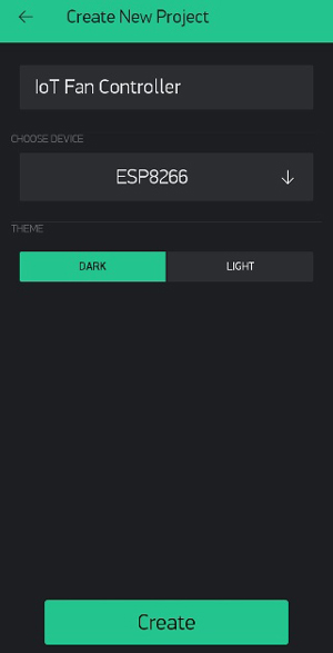
After successful installation, open the application, and there we will get a screen with an option “New Project”. Click on it and it will pop up a new screen, where we need to set the parameters like Project Name, Board, and Connection Type. In our project, select the device as “ESP8266” and connection type as “Wi-Fi” and click on “Create”.
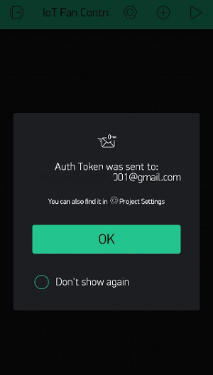
After the successful creation of the project, you will get an Authenticate ID in our registered mail. Save the Authenticate ID for future reference.
Now, the next step is adding the widgets to control the Fan speed and turning on/off the fan. For that, click on the + sign and add the Slider widget.
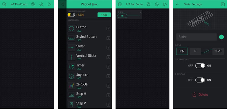
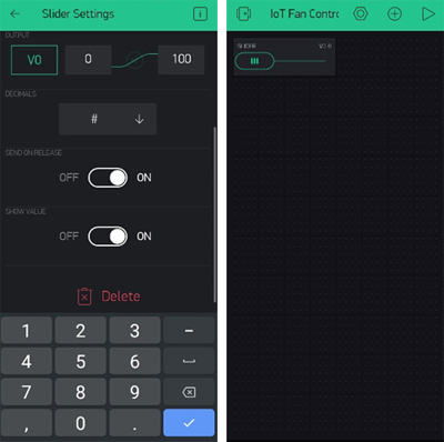
After dragging the widgets to our project, now we have to set its parameters which are used to send the slider values to ESP. Click on slider, then we will get a screen named slider setting. Click on the PIN and select the PIN type as Virtual and the Pin name as V0. This Pin will be accessed by the BLYNK App.
Then choose the Slider range from 0 to 100.
Code for IoT Based Fan Speed Controller
The complete code for AC fan speed control using ESP8266 can be found at the end of the document. To understand how this Fan controller code works, here we are going to explain the code in small snippets. Firstly, thanks to RobotDynOfficial for excellent library support of AC dimmer using TRIAC and Zero Cross Detection. The library that is used, can be installed from the below GitHub link.
https://github.com/RobotDynOfficial/RBDDimmer
Since we used Blynk, the code architecture is used from Blynk example - Virtual Pin Read
BLYNK_WRITE(V0)
{
  int pinValue = param.asInt(); // assigning incoming value from pin V1 to a variable
  pwm = pinValue;
  buzz_notify();
  Serial.println("PWM value received - ");
  Serial.println(pwm);
  Serial.println("\n");
}
The above function is getting called whenever a new value or slider is changed on the Blynk app and the PWM output value is set. During these changes, the Buzzer starts to beep.
void loop()
{
  Blynk.run();
  map_pwm = map(pwm, 0, 100, 0, 87); // analogRead(analog_pin), min_analog, max_analog, 0%, 100%);
  dimmer.setPower(map_pwm); // name.setPower(0%-100%)
}
87% is used as during testing the maximum power is reached at 87%. For a detailed code explanation kindly go through the code comments in the code section at the bottom of this page.
Controlling Fan Speed using Blynk and ESP-12E
With my IoT based fan controller circuit ready for action, I went to my wall fan, traced its wires and connected the Fan controller setup as shown in below image. With this done, now I can control my fan from my phone.
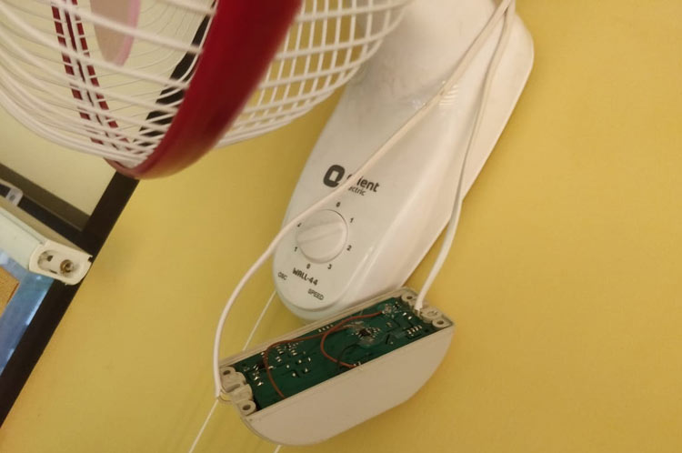
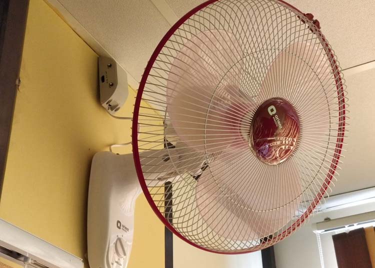
Similarly, you can control your fan wirelessly using your phone or laptop. You can also set timers on the blynk application to automatically turn on/off the fan at a particular time of the day. A full working video and code can be found below. Hope you enjoyed the project and learned something useful, if you have any questions, please leave them in the comment section below or use our forum to start a discussion on this.
Complete Project Code
#define BLYNK_PRINT Serial
#include <ESP8266WiFi.h>
#include <BlynkSimpleEsp8266.h>
#include <RBDdimmer.h>
#define outputPin  14
#define zerocross  4 // for boards with CHANGEABLE input pins
#define buzz 5
//#define TRIAC 14
int pwm=0;
int map_pwm=0;
// You should get Auth Token in the Blynk App.
// Go to the Project Settings (nut icon).
char auth[] = "BLYNK TOKEN";
// Your WiFi credentials.
// Set password to "" for open networks.
char ssid[] = "xxxx";
char pass[] = "xxxxxx";
//void ICACHE_RAM_ATTR ISRoutine();
dimmerLamp dimmer(outputPin, zerocross); //initialase port for dimmer for ESP8266, ESP32, Arduino due boards
int outVal = 0;
void buzz_notify (void){
  digitalWrite(buzz, HIGH);
  delay(1000);
  digitalWrite(buzz, LOW);
  delay(1000);
}
BLYNK_WRITE(V0)
{
  int pinValue = param.asInt(); // assigning incoming value from pin V1 to a variable
  pwm = pinValue;
  buzz_notify();
  Serial.println("PWM value received - ");
  Serial.println(pwm);
  Serial.println("\n");
}
void setup()
{
  // Debug console
  pinMode(buzz,OUTPUT);
  Serial.begin(115200);
  buzz_notify ();
  Blynk.begin(auth, ssid, pass);
  dimmer.begin(NORMAL_MODE, ON); //dimmer initialisation: name.begin(MODE, STATE)
// void ICACHE_RAM_ATTR ISRoutine();
  // You can also specify server:
  //Blynk.begin(auth, ssid, pass, "blynk-cloud.com", 80);
  //Blynk.begin(auth, ssid, pass, IPAddress(192,168,1,100), 8080);
}
void loop()
{
  Blynk.run();
  map_pwm = map(pwm, 0, 100, 0, 87); // analogRead(analog_pin), min_analog, max_analog, 100%, 0%);
dimmer.setPower(map_pwm); // name.setPower(0%-100%)
}
Comments
Will this dimmer work with
Will this dimmer work with nin inductive load?
I tried uploading the library to nodemcu but MCU keep crashing.
Hi Raj, can you share the
Hi Raj, can you share the error message displayed on serial monitor when NodeMCU crashes.

If we install same circuit for the Ceiling fan, will it make the humming sound? I had tried making a similar circuit, however, after installing for a ceiling fan, fan made humming noise for lower speeds. How can this noise be reduced / eliminated ?