
IoT and home automation have come a long way since they first gained popularity in 2014, thanks to the debut of a game-changing IC called the ESP8266 by espressif systems. Today we know it as the nodeMCU module and in many of our projects, we have used this IC to build many home automation projects where our focus was on building AC Motor Speed Control or Phase Angle Control systems. But one of the major problems we faced doing it was the noise it generated and the vibration that the motor had due to timing issues introduced by the microcontroller. That's why in this article, we are going to solve this problem by introducing a second microcontroller in our circuit, while also ensuring that the BOM remains as cheap as possible. Also the whole module is made snug and fits perfectly into an enclosure thanks to the wonderful PCBs fabricated by PCBway. So without further ado let's get right into it.
Why are we Doing Another Home Automation Project?
If you are a regular follower of circuit digest you might know that we have built a lot of home automation projects like-
IoT Based Smart Fan Control using ESP8266 and Blynk
Compact Smart Switch with 3D Printed Enclosure
ESP8266 based Smart Plug to Make Your Home Appliances IoT Enabled
You might be asking yourself why we are doing another home automation project. The answer to this question is simple, we wanted to rectify some existing problems that came along with building some of those projects. Some of those projects were big and bulky, for others, you need to completely rewire your existing switch box to fit the circuit board inside. But the biggest problem lies with phase angle control. In this project, we wanted to solve all these issues and we also wanted to make it compact and modular so that it could solve the installation issues.
How does the Modular Automation Circuit Work?
Before we proceed any further in the article let's see how this circuit works. The working of the circuit is very simple and easy to understand. To solve the above-mentioned noise problem we are using two microcontrollers in which one is a PIC microcontroller and the other is the ESP8266 microcontroller. The ESP generates a PWM signal that is filtered by a RC filter network and gets smoothed out to a DC signal. This DC signal is fed to the ADC of the PIC microcontroller and the PIC controls the speed of the ceiling fan by reading the ADC value. We also have an onboard temperature sensor and a buzzer. The onboard temperature sensor is used to get the temperature data and the buzzer beeps every time the user interacts with the web interface.
Components Required to Build IoT based Modular Automation System
The components required to build the IoT-based modular automation system are listed below. Most of the components are generic and can be found in any online store which makes the replication process very easy.
- ESP8266-01 Wifi Module - 1
- PIC12F675 Microcontroller - 1
- DHT11 Temperature and Humidity Sensor - 1
- MB10S Bridge Rectifier - 1
- PC817 Optocoupler - 1
- BT136 Triac - 1
- MOC3021 Triac Driver - 1
- HLK-PM03 Hi-Link - 3.3V - 1
- MMBT2222A Transistor - 1
- Buzzer 12mm - 1
- 10uF Capacitor - 1
- 1K Resistor - 1
- 47R Resistor - 2
- 470R Resistor - 1
- 102pF,2KV Capacitor - 1
- 10K Resistor - 1
- 100K Resistor - 2
Schematic of IoT Enabled Fan Speed Regulator
The complete circuit diagram of the IoT-enabled Modular home automation system is shown below.

As you can see the circuit is very simple and does not need many components to build. Let's start our explanation with the ESP8266-01 Wi-Fi module. You can also check out the video at the bottom of the page for a more detailed project explanation. To program the module, you need to first flash the firmware on the ESP8266 module and you also need to flash the firmware on the PIC12F675 module before doing anything.
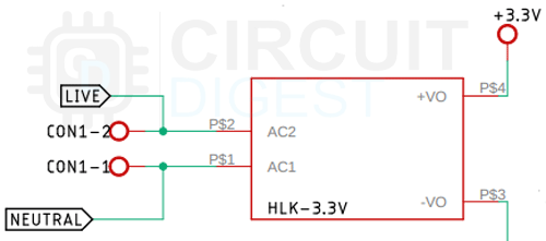
First, we have our power supply module, we are using a 220V to 3.3V hylink power Supply module to power the whole project.
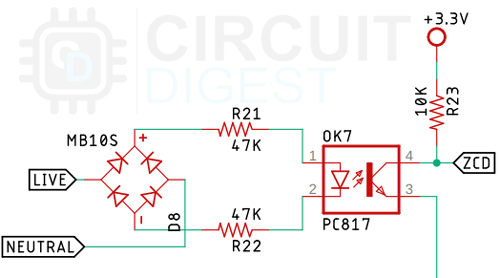
Next, we have our zero-crossing detection circuit. The zero-crossing detection circuit is used to generate interrupts, these interrupts are detected by the PIC microcontroller, and then it is used to trigger the triac circuit.
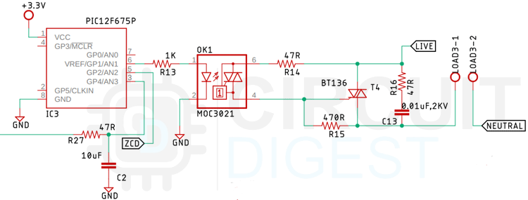
Next, we have our triggering circuit for TRIAC, the whole phase angle control system is monitored and supervised by this PIC microcontroller. This controller drives a MOC3021 opto triac driver and that in turn drives the BT136 TRIAC. This TRIAC also has a Resistor and a capacitor as snubber circuit prevents noise introduced by the phase angle control circuit.
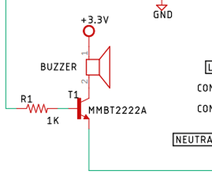
Next, we have our buzzer, we are using a MMB2222A transistor to drive the buzzer and to limit the current through the transistor base, we are using a 1K resistor.
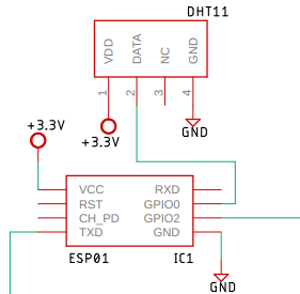
Next, we have the ESP8266-01 module and the DHT11 Temperature and Humidity Sensor that is connected to the GPIO0 of the ESP8266-01 Module. This is possible because the pin of the esp module always stays high and the ESP GP0 pin should be kept high to put the device in normal operation mode.
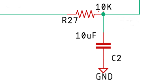
Finally, we have a RC filter that is connected from the ESP-01 to the PIC microcontroller. This filter is responsible for converting the PWM signal generated by the ESP to a smooth DC signal that the PIC microcontroller is going to read through the ADC.
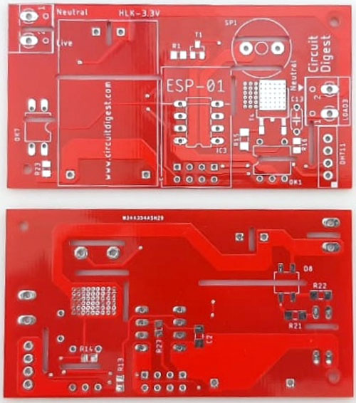
PCB Design for Modular Home Automation
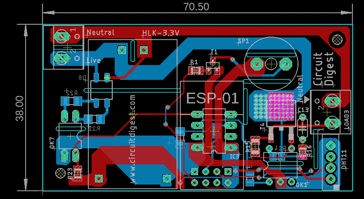
As you can see in the above image, the PCB is designed with EAGLE PCB design software and it has a dimension of 70.5mm X 38mm.
Top Side of the Modular Home Automation PCB:
The top side of the PCB is shown above, it's a double layer PCB with proper isolation on the high voltage and low voltage sides. As we are using eagle PCB design software, it gives us the flexibility to get a 2D view of the PCB so it's shown in the image above.
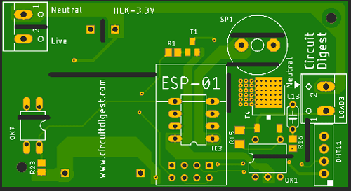
Bottom Side of the Modular Home Automation PCB:
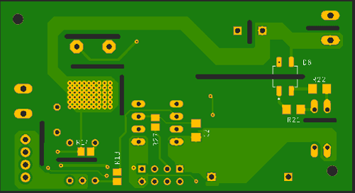
The bottom side of the PCB is shown above, as you can also see we have placed some SMD components at the bottom of the PCB and we have used the Via Stitching method in place of the TRIAC that is T4 on the board. We did so to improve the thermal of the PCB.
Ordering the Home Automation PCB from PCBWay
After finalizing the design, you can proceed with ordering the PCB:
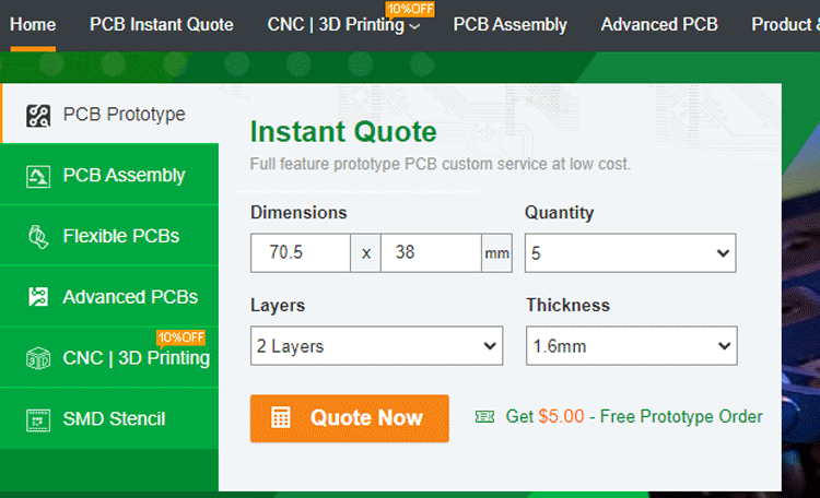
Step 1: Go to https://www.pcbway.com/, and sign up if this is your first time. Then, in the PCB Prototype tab, enter the dimensions of your PCB, the number of layers, and the number of PCBs you require.
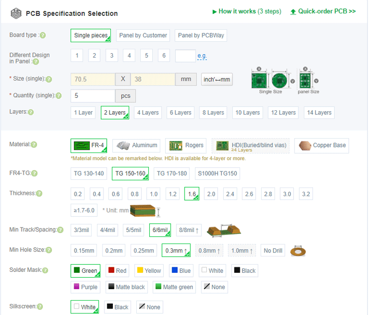
Step 2: Proceed by clicking on the ‘Quote Now’ button. You will be taken to a page where you need to set a few additional parameters like the Board type, Layers, Material for PCB, Thickness, and more. Most of them are selected by default, but if you are opting for specific parameters, you can select them here.
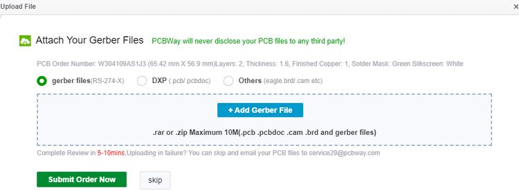
Step 3: The final step is to upload the Gerber file and proceed with the payment. To make sure the process is smooth, PCBWAY verifies if your Gerber file is valid before proceeding with the payment. This way, you can be sure that your PCB is fabrication-friendly and you will receive it as committed.
Assembling our Modular Automation PCB
After a few days, we received our PCB in a neat package and the PCB quality was good as always. The top layer and the bottom layer of the board are shown below:
After making sure the tracks and footprints were correct, I proceeded with assembling the PCB. The image here shows how the completely soldered board looks like.
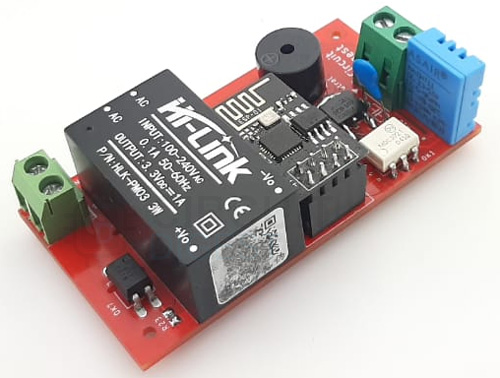
As you can see in the image, all the components are soldered properly. As mentioned earlier, all the components for this project are easily available so the replication project is very easy. You can also download the Gerber File so you can order your PCB if you need to.
Programming onboard PIC12F675 Microcontroller and ESP12-E Microcontroller
The code section for this project will be divided into three sections because we are using two microcontrollers in our schematic, first one is an ESP8266 microcontroller and the second is a PIC microcontroller as you can see from the schematic. So the code for those two microcontrollers will be different and there will be another section where we will explain all the details about the webpage section.
Understanding the code for PIC Microcontroller:
In this section, we will explain how the code for the PIC microcontroller works. We start our code by including all the required libraries in which some are builtin libraries and some are custom libraries. We also define all the required variables.
#include <xc.h>
#include "config.h"
#include "pinmanager.h"
#include "peripherals.h"
unsigned int ADC_AVG;
Next, we declare and define all the required functions that are needed for this code to work. The functions are enable_interrupt(): which is used to enable the external interrupt in the PIC Microcontroller. We also have disable_interrupt(): that is used to disable interrupt.
void enable_interrupt(){
    INTERRUPT_EDGE = FALLING;
    GLOBAL_INTERRUPT = ENABLE;
    EXTERNAL_INTERRUPT = ENABLE;
}
void disable_interrupt(){
    GLOBAL_INTERRUPT = DISABLE;
    EXTERNAL_INTERRUPT = DISABLE;
}
Next, we have our ADCInit() function that is used to configure the ADC for the PIC microcontroller.
void ADCInit()
{
   ADCON0bits.ADFM = 0; // Right Justified bit 7
   ADCON0bits.VCFG = 0; // Voltage Reference VDD bit 6
   ADCON0bits.CHS1 = 1; //set AN3 as input
   ADCON0bits.CHS0 = 1;//set AN3 as input
   ADCON0bits.ADON = 1;
   ADC_PORT = INPUT;
   ANSELbits.ANS3 = 1;
}
Up next we have our __custom_delay(unsigned int delay_data) function, in PIC microcontroller with XC8 we don't have the option to pass variables with the built-in delay function so this becomes necessary.
void __custom_delay(unsigned int delay_data){
    for(int i =0; i < delay_data; i++)
    {
        __delay_us(1);
    }
}
Next, we have defined the function through which we are processing the incoming ADC data from the pin of the microcontroller and that returns 8-bit ADC data.
unsigned int GetAdcvalue()
{
    ADCON0bits.GO = 1; //start the conversion
    __delay_us(200);
    while(ADCON0bits.GO==1){}; //wait for the conversion to end
    return ADRESH; //take the most significant bytes
}
Finally, we have our interrupt function, in the interrupt function the whole TRIAC control happens. As a rule of thumb, you should not put any code inside the ISR function, but the timing of the Phase Angle Control is so critical that you need to execute the function in the interrupt service routine, otherwise there will be vibration and jitters.
void __interrupt() my_isr(){
    if(EXTERNAL_INTERRUPT_FLAG)
    {
        disable_interrupt();
        EXTERNAL_INTERRUPT_FLAG =0;
        for(int j = 0; j<10; j++)
        {
            ADC_AVG = ADC_AVG + GetAdcvalue();
            __delay_us(50);
        }
        ADC_AVG = ADC_AVG / 10;
        __custom_delay(ADC_AVG);
        TRIAC_PIN = HIGH;
        __delay_us(50);
        TRIAC_PIN = LOW;
        enable_interrupt();
   }
}
Next, we have the main function, in the main function we call all the init functions and we set up the GPIO Interrupts and ADC. And we left the while loop inside the main empty.
void main(void) {
    GP0_GP1_as_io();
    init();
    enable_interrupt();
    ADCInit();
  while(1)
    ;
    return;
}
This marks the end of our code for the PIC microcontroller section and we can move on to the code for the ESP8266 Microcontroller.
Understanding the code for ESP8266-01 Microcontroller:
The ESP8266 is the brain of the circuit and it serves many purposes. It serves the webpage, generates the PWM signal for the PIC microcontroller, and powers the buzzer to let the user know when a command is received.
We start our code by including all the required libraries: ESP8266WiFi, ESP8266mDNS, ArduinoOTA, Adafruit_Sensor, DHT, ESPAsyncTCP, and ESPAsyncWebServer and ESP_EEPROM.
// Import required libraries
#include <ESP8266WiFi.h>
#include <ESPAsyncTCP.h>
#include <ESPAsyncWebServer.h>
#include <Adafruit_Sensor.h>
#include <DHT.h>
#include <Hash.h>
#define DHTPIN 0
#include <ESP_EEPROM.h>
Next, we have defined the type of DHT sensor that we are using for this. We are using the DHT11 sensor, so we have defined just that.
#define DHTTYPE DHT11
Next, we have defined all the required variables in this project. In this section, we have first defined SSID and Password, then we have defined the pwm output pin and the DHT pin of the sensor. Next, we define sliderValue and variables for temperature and humidity. Next, we declare another three variables temp_low, temp_high, and temp_range that are going to be used to store the data input by the user. Next, we have our three variables one of them is auto_manual_mode which stores the mode data of the module and the final two variables are used to control the buzzer in the circuit.
float t = 0.0;
unsigned long previousMillis = 0;
const long interval = 5000;
const char* ssid = "Fan Speed Controller";
//const char* password = "12345678";
const char* password = "12345678";
const int output_pin = 2;
String sliderValue = "0";
String temp_min, temp_max;
const char* PARAM_INPUT = "value";
const char* Temp_Min = "tempMin";
const char* Temp_Max = "tempMax";
float temp_range;
bool auto_manual_mode = 0; // 1 is auto mode o is manual mode
int tmp_mode, tmp_slider = 0;
Next, we initialize the DHT instance and pass on the DHT pin and DHT type which we have declared at the start of the code, after that we also initialize the AsyncWebServer server(80) instance on port 80.
 DHT dht(DHTPIN, DHTTYPE);
// Create AsyncWebServer object on port 80
AsyncWebServer server(80);
Next, we have our setup function, in the setup function at first we set the TX pin of the ESP as IO and we set it as output and set that to LOW so that the buzzer won't beep immediately as the ESP boots up. Next, we initialize the serial for debugging and we also begin the EEPROM. Next, we call the EEPROM.get method. The idea is that in times of a power cut the module will resume its operation.
 // Serial port for debugging purposes
  pinMode(1, FUNCTION_3);
  pinMode(3, FUNCTION_3);
  pinMode(1, OUTPUT);
  pinMode(3, OUTPUT);
  digitalWrite(1, HIGH);
  Serial.begin(115200);
  EEPROM.begin(30);
  EEPROM.get(0, auto_manual_mode);
  float a, b;
  int c;
  EEPROM.get(4, a);
  EEPROM.get(12, b);
  EEPROM.get(20, c);
  temp_min = String(a);
  temp_max = String(b);
  sliderValue = String(c);
//  Serial.println("\n");
//  delay(2000);
//  Serial.println(auto_manual_mode);
//  Serial.println(temp_min);
//  Serial.println(temp_max);
//  Serial.println(sliderValue);
Next, we apply the changes by calling the main_loop() function and we set up the ESP as access point mode. Next, we initialize all the servers on instances of the ESP. With help of this, we will control the slider, get data from the form and we will also display the temperature reading on the webpage.
 main_loop();
  WiFi.mode(WIFI_AP);
  WiFi.softAP(ssid, password); / Set access point
  // Route for root / web page
  server.on("/", HTTP_GET, [](AsyncWebServerRequest * request) {
    request->send_P(200, "text/html", index_html, processor);
  });
  // Send a GET request to <ESP_IP>/slider?value=<inputMessage>
  server.on("/slider", HTTP_GET, [] (AsyncWebServerRequest * request) {
    String inputMessage;
    // GET input1 value on <ESP_IP>/slider?value=<inputMessage>
    if (request->hasParam(PARAM_INPUT)) {
      inputMessage = request->getParam(PARAM_INPUT)->value();
      sliderValue = inputMessage;
      auto_manual_mode = 0; // set to manual mode
      EEPROM.put(0, auto_manual_mode);
      EEPROM.put(20, sliderValue.toInt());
      Serial.println(auto_manual_mode);
      boolean ok2 = EEPROM.commit();
      Serial.println((ok2) ? "Second commit OK" : "Commit failed");
    }
    else {
      inputMessage = "No message sent";
    }
    Serial.println(inputMessage);
    request->send(200, "text/plain", "OK");
  });
  server.on("/temperature", HTTP_GET, [](AsyncWebServerRequest * request) {
    request->send_P(200, "text/plain", String(t).c_str());
  });
  // Send a GET request to <ESP_IP>/get?inputString=<inputMessage>
  server.on("/get", HTTP_GET, [] (AsyncWebServerRequest * request) {
    String inputMessage;
    // GET inputString value on <ESP_IP>/get?inputString=<inputMessage>
    if (request->hasParam(Temp_Min)) {
      inputMessage = request->getParam(Temp_Min)->value();
      temp_min = inputMessage;
      EEPROM.put(4, temp_min.toFloat());
      EEPROM.commit();
      Serial.println(temp_min);
      //writeFile(SPIFFS, "/inputString.txt", inputMessage.c_str());
    }
    // GET inputInt value on <ESP_IP>/get?inputInt=<inputMessage>
    if (request->hasParam(Temp_Max)) {
      inputMessage = request->getParam(Temp_Max)->value();
      temp_max = inputMessage;
      EEPROM.put(12, temp_max.toFloat());
      EEPROM.commit();
      Serial.println(temp_max);
      // writeFile(SPIFFS, "/inputInt.txt", inputMessage.c_str());
    }
    // GET inputFloat value on <ESP_IP>/get?inputFloat=<inputMessage>
    else {
      inputMessage = "No message sent";
    }
    //Serial.println(inputMessage);
    //request->send(200, "text/text", "<html><body><h3>Data Set to ESP</h3></body></html>");
    auto_manual_mode = 1; // set to auto mode
    EEPROM.put(0, auto_manual_mode);
    Serial.println(auto_manual_mode);
    boolean ok1 = EEPROM.commit();
    Serial.println((ok1) ? "First commit OK" : "Commit failed");
  });
  // Start server
  server.begin();
}
Next, we have the loop function, in the loop function we first call the main_loop() function. We make the TX pin of the device Low so that the buzzer won't make a sound. Next, we check the auto manual mode flag and check it with the previous value, this is done so that we could detect any changes that happen, and if we detect any changes, we beep the buzzer. If we detect the user-enabled auto mode, we beep the buzzer twice.
void loop() {
  main_loop();
  digitalWrite(1, HIGH);
  if (auto_manual_mode != tmp_mode) {
    if (auto_manual_mode == 1) {
      digitalWrite(1, LOW);
      delay(500);
      digitalWrite(1, HIGH);
      delay(500);
      digitalWrite(1, LOW);
      delay(500);
      digitalWrite(1, HIGH);
      delay(500);
    }
    tmp_mode = auto_manual_mode;
  }
  if (sliderValue.toInt() != tmp_slider)
  {
    digitalWrite(1, LOW);
    delay(500);
    digitalWrite(1, HIGH);
    tmp_slider = sliderValue.toInt();
  }
}
Next, we have the main loop function, inside this function, we first get the current timer value with the mills() function, and check if the timer counter exceeds the interval value. If so, we set the previousMillis value to currentMillis and get the temperature data from the DHT11 sensor.
Understand the Webpage made with HTML and CSS:
We are using a web page made with HTML and CSS to make a web interface through which we can control all the features of the modular home automation device. Inside the index_html.h file, we are going to define all the CSS that is required to make the webpage look clean and we will explain the html code next.
We start our code by index html and after that, we use the <meta> tag to make your web page responsive in any browser.
<meta name="viewport" content="width=device-width, initial-scale=1">
Between the <style></style> tags, we add some CSS to style the web page.
body{
  margin:0;
  padding: 0;
  color:#1c1c1c;
  font-family: roboto;
  position: relative;
  text-align:center;
}
p{margin:0;padding:0;}
.clr{
  clear:both;
}
@font-face {
  font-family: quartz;
  src: url(fonts/quartz.ttf);
}
#bg_mob{
  background-color: #f4f4f4;
  max-width: 540px;
  margin:0 auto;
  height:100vh;
}
.mob_inner{
  padding: 15px;
}
#espRange {
  -webkit-appearance: none;
  width: 100%;
  height: 15px;
  border-radius: 5px;
  background: #0e3d79;
  outline: none;
}
.slideresp:hover {
  opacity: 1;
}
.slideresp::-webkit-slider-thumb {
  -webkit-appearance: none;
  appearance: none;
  width: 28px;
  height: 28px;
  border-radius: 50%;
  background: #00acec;
  cursor: pointer;
}
.slideresp::-moz-range-thumb {
  width: 28px;
  height: 28px;
  border-radius: 50%;
  background: #00acec;
  cursor: pointer;
}
.value{
    width: 100px;
    background: #ff7700;
    margin: 0 auto;
    padding: 5px;
    margin-top: 10px;
    color: white;
}
#temperature_sec{margin: 30px 0;}
.form_max-min input
    padding: 6px 4px;
    border: 1px solid #c8c8c8;
}
#esp-submit{
    background-color: #ff7700;
    color: white;
    border: none;
    padding: 5px 10px;
    font-size: 16px;
}
.form_max-min{margin:35px 0;}
input[type=number]::-webkit-inner-spin-button,
input[type=number]::-webkit-outer-spin-button {
  -webkit-appearance: none;
}
  </style>
Inside this we customize the slider, we set the temperature display box and set the form as we desire and we also set all the colors, height, width, and padding parameters.
Inside the <body></body> tags, we add contents for our webpage. The two div tags give the body an id and a class through which we can implement styling to the whole body of the webpage.The <h2></h2> tags add a heading to the web page. In this case, the “ESP Fan Speed Controller” text,
<div id="bg_mob">
    <div class="mob_inner">
      <div class="slidecontainer">
        <h2>ESP Fan Speed Controller</h2>
Next, we create a slider, To create a slider in HTML you use the <input> tag. The <input> tag specifies a field where the user can enter data. If you are looking for input types, there are many input types to make a slider, you need to use the type attribute with range value. In the slider, you also need to define the min and max range of the slider. For our case, it's 0 to 100. Additionally, you need to specify ID, class, on change, and more. The onchange type is used to call a function so that we could commit the changes in the esp.
<input type="range" onchange="updateSliderPWM(this)" id="espRange" min="0" max="100" value="%SLIDERVALUE%" step="1" class="slideresp" style="height:18px;width:290px; border-radius:5px;background:#0e3d79;outline:none;">
Next, we have a paragraph tag that will show the slider value when the user is changing the slider in real-time.
<p style="width: 60px;background: #ff7700;margin: 0 auto;padding: 6px 12px;color: white;"><span id="textSliderValue">%SLIDERVALUE%</span></p>
Like this, we do the same to display the temperature and we also do the same for setting up the form.
</div>
<hr style="margin-top: 35px;border: 1px solid #e6e5e5;">
<div id="temperature_sec">
<div>
<h2><i class="fa fa-thermometer-half" style="color: #ec5a00;margin-right: 10px;"></i>Room Temperature <span id="temperature" style="background:#dddddd;padding: 3px 12px;">%TEMPERATURE%<sup class="units">°C</sup></span></h2>
</div>
</div>
<hr style="margin-top: 35px;border: 1px solid #e6e5e5;">
<form action="/get" class="form_max-min">
<label><b>Min: </b> </label>
<input type="number" id="quantity" min="10" placeholder="Min 10" name="tempMin"><br><br>
<label><b>Max: </b> </label>
<input type="number" id="quantity" max="60" placeholder="Max 60" name="tempMax"><br><br>
<input type="submit" id="esp-submit" value="Enable Auto Mode" onclick="submitMessage()">
</form>
<p style="text-align: left;background: #e8e8e8;padding: 10px;font-size: 14px;line-height: 22px;color: black;"><b>Note :</b> This device features an auto and manual mode function; users can enable auto speed control mode by inputting the desired temperature range(Min and Max Value) and clicking on the Enable Auto Mode button. If the slider is moved while auto mode is enabled the device automatically reverts back to manual speed control mode.</p>
</div>
</div>
Finally, we make all the functions that are defined inside the body of the html file and we make a get request using the new XMLHttpRequest(); function.
<script>
function updateSliderPWM(element) {
  var sliderValue = document.getElementById("espRange").value;
  document.getElementById("textSliderValue").innerHTML = sliderValue;
  console.log(sliderValue);
  var xhr = new XMLHttpRequest();
  xhr.open("GET", "/slider?value="+sliderValue, true);
  xhr.send();
}
setInterval(function ( ) {
  var xhttp = new XMLHttpRequest();
  xhttp.onreadystatechange = function() {
    if (this.readyState == 4 && this.status == 200) {
      document.getElementById("temperature").innerHTML = this.responseText;
    }
  };
  xhttp.open("GET", "/temperature", true);
  xhttp.send();
}, 5000 ) ;
function submitMessage() {
      alert("Saved value to ESP SPIFFS");
      setTimeout(function(){ document.location.reload(false); }, 500);
    }
</script>
</body>
</html>
)rawliteral";
This way, when the ESP8266 receives the GET request, it can retrieve the value parameter in the URL and control the PWM signal accordingly as we’ll see in the next sections.
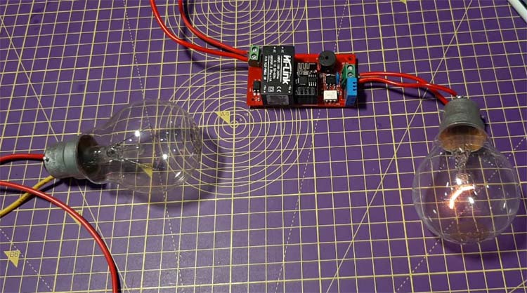
Testing the Modular Home Automation PCB
Once the PCB was done, we uploaded the code for both the PIC microcontroller and the ESP8266 microcontroller and we started testing the PCB. For our first test, we connected a 100Watt bulb in series with the circuit so that if anything goes wrong the bulb will protect the circuit.
Next, we disconnected the series bulb and tested the circuit if it was working properly or not and sure enough the circuit was working properly.
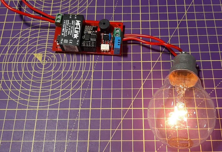
Then we tested the auto and manual mode functionality of the circuit and it was also working properly.
This marks the end of our article. If you have any questions regarding the project you can post them in the comment section below or use our technical forum to start a discussion.
Complete Project Code
// Import required libraries
#include <ESP8266WiFi.h>
#include <ESPAsyncTCP.h>
#include <ESPAsyncWebServer.h>
#include <Adafruit_Sensor.h>
#include <DHT.h>
#include <Hash.h>
#define DHTPIN 0
#include <ESP_EEPROM.h>
#include"index_html.h"
#define DHTTYPE    DHT11
float t = 0.0;
unsigned long previousMillis = 0;
const long interval = 3000;
const char* ssid = "Fan Speed Controller";
const char* password = "12345678";
const int output_pin = 2;
String sliderValue = "0";
String temp_min, temp_max;
const char* PARAM_INPUT = "value";
const char* Temp_Min = "tempMin";
const char* Temp_Max = "tempMax";
float temp_range;
bool auto_manual_mode = 0; // 1 is auto mode o is manual mode
int tmp_mode, tmp_slider = 0;
DHT dht(DHTPIN, DHTTYPE);
// Create AsyncWebServer object on port 80
AsyncWebServer server(80);
String processor(const String& var) {
  //Serial.println(var);
  if (var == "SLIDERVALUE") {
    return sliderValue;
  }
  else if (var == "TEMPERATURE") {
    return String(t);
  }
  else if (var == "tempMin") {
    return temp_min;
  }
  else if (var == "tempMax") {
    return temp_max ;
  }
  return String();
}
void main_loop();
void setup() {
  // Serial port for debugging purposes
  pinMode(1, FUNCTION_3);
  pinMode(3, FUNCTION_3);
  pinMode(1, OUTPUT);
  pinMode(3, OUTPUT);
  digitalWrite(1, HIGH);
  dht.begin();
  Serial.begin(115200);
  EEPROM.begin(30);
  EEPROM.get(0, auto_manual_mode);
  float a, b;
  int c;
  EEPROM.get(4, a);
  EEPROM.get(12, b);
  EEPROM.get(20, c);
  temp_min = String(a);
  temp_max = String(b);
  sliderValue = String(c);
  //  Serial.println("\n");
  //  delay(2000);
  //  Serial.println(auto_manual_mode);
  //  Serial.println(temp_min);
  //  Serial.println(temp_max);
  //  Serial.println(sliderValue);
  main_loop();
  WiFi.mode(WIFI_AP);
  WiFi.softAP(ssid, password);
  // Route for root / web page
  server.on("/", HTTP_GET, [](AsyncWebServerRequest * request) {
    request->send_P(200, "text/html", index_html, processor);
  });
  // Send a GET request to <ESP_IP>/slider?value=<inputMessage>
  server.on("/slider", HTTP_GET, [] (AsyncWebServerRequest * request) {
    String inputMessage;
    // GET input1 value on <ESP_IP>/slider?value=<inputMessage>
    if (request->hasParam(PARAM_INPUT)) {
      inputMessage = request->getParam(PARAM_INPUT)->value();
      sliderValue = inputMessage;
      auto_manual_mode = 0; // set to manual mode
      EEPROM.put(0, auto_manual_mode);
      EEPROM.put(20, sliderValue.toInt());
      Serial.println(auto_manual_mode);
      boolean ok2 = EEPROM.commit();
      Serial.println((ok2) ? "Second commit OK" : "Commit failed");
    }
    else {
      inputMessage = "No message sent";
    }
    Serial.println(inputMessage);
    request->send(200, "text/plain", "OK");
  });
  server.on("/temperature", HTTP_GET, [](AsyncWebServerRequest * request) {
    request->send_P(200, "text/plain", String(t).c_str());
  });
  // Send a GET request to <ESP_IP>/get?inputString=<inputMessage>
  server.on("/get", HTTP_GET, [] (AsyncWebServerRequest * request) {
    String inputMessage;
    // GET inputString value on <ESP_IP>/get?inputString=<inputMessage>
    if (request->hasParam(Temp_Min)) {
      inputMessage = request->getParam(Temp_Min)->value();
      temp_min = inputMessage;
      EEPROM.put(4, temp_min.toFloat());
      EEPROM.commit();
      Serial.println(temp_min);
      //writeFile(SPIFFS, "/inputString.txt", inputMessage.c_str());
    }
    // GET inputInt value on <ESP_IP>/get?inputInt=<inputMessage>
    if (request->hasParam(Temp_Max)) {
      inputMessage = request->getParam(Temp_Max)->value();
      temp_max = inputMessage;
      EEPROM.put(12, temp_max.toFloat());
      EEPROM.commit();
      Serial.println(temp_max);
      // writeFile(SPIFFS, "/inputInt.txt", inputMessage.c_str());
    }
    // GET inputFloat value on <ESP_IP>/get?inputFloat=<inputMessage>
    else {
      inputMessage = "No message sent";
    }
    //Serial.println(inputMessage);
    //request->send(200, "text/text", "<html><body><h3>Data Set to ESP</h3></body></html>");
    auto_manual_mode = 1; // set to auto mode
    EEPROM.put(0, auto_manual_mode);
    Serial.println(auto_manual_mode);
    boolean ok1 = EEPROM.commit();
  });
  // Start server
  server.begin();
}
void loop() {
  unsigned long currentMillis = millis();
  if (currentMillis - previousMillis >= interval) {
    // save the last time you updated the DHT values
    previousMillis = currentMillis;
    // Read temperature as Celsius (the default)
    // float temp_tmp = dht.readTemperature();
    t = dht.readTemperature();
  }
  main_loop();
  pinMode(1, FUNCTION_3);
  pinMode(3, FUNCTION_3);
  pinMode(1, OUTPUT);
  pinMode(3, OUTPUT);
  digitalWrite(1, HIGH);
  if (auto_manual_mode != tmp_mode) {
    if (auto_manual_mode == 1) {
      digitalWrite(1, LOW);
      delay(500);
      digitalWrite(1, HIGH);
      delay(500);
      digitalWrite(1, LOW);
      delay(500);
      digitalWrite(1, HIGH);
      delay(500);
    }
    tmp_mode = auto_manual_mode;
  }
  if (sliderValue.toInt() != tmp_slider)
  {
    digitalWrite(1, LOW);
    delay(500);
    digitalWrite(1, HIGH);
    tmp_slider = sliderValue.toInt();
  }
}
void main_loop()
{
  if (auto_manual_mode == 0) // thi is manual mode the value is 0
  {
    int val = map(sliderValue.toInt(), 0, 100, 255, 0);
    analogWrite(output_pin, val);
  }
  if (auto_manual_mode) // auto mode
  {
    temp_range = (temp_max.toFloat() - temp_min.toFloat()) / 10;
    if (temp_max.toFloat() <= t)
    {
      analogWrite(output_pin, 25);
    }
    else if ((temp_min.toFloat() + (temp_range * 9)) <= t)
    {
      analogWrite(output_pin, 50);
    }
    else if ((temp_min.toFloat() + (temp_range * 8)) <= t)
    {
      analogWrite(output_pin, 100);
    }
    else if ((temp_min.toFloat() + (temp_range * 7)) <= t)
    {
      analogWrite(output_pin, 125);
    }
    else if ((temp_min.toFloat() + (temp_range * 6)) <= t)
    {
      analogWrite(output_pin, 150);
    }
    else if ((temp_min.toFloat() + (temp_range * 5)) <= t)
    {
      analogWrite(output_pin, 175);
    }
    else if ((temp_min.toFloat() + (temp_range * 4)) <= t)
    {
      analogWrite(output_pin, 200);
    }
    else if ((temp_min.toFloat() + (temp_range * 3)) <= t)
    {
      analogWrite(output_pin, 225);
    }
    else if ((temp_min.toFloat() + (temp_range * 2)) <= t)
    {
      analogWrite(output_pin, 250);
    }
    else if ((temp_min.toFloat() + (temp_range * 1)) <= t)
    {
      analogWrite(output_pin, 255);
    }
  }
}
Comments
Would it be possible to make something similar for integrating with Home Assistant? This way there is no need for a webserver or 2nd microcontroller. The ESP8266 could be flashed with ESPhome, integrated with Homa Assistant and controlled from there on. This would make the design way easier. Unfortunately I lack the knowledge of changing this design in to a HA project. Do you guys have any Home Assistant knowledge or experience and willing to help?

How to import the above code to the equipment and how to get the webpage in mobile
Pls guide me