

Ever felt lazy in getting up from the comfort of your bed to turn off that light switch. So here we have a cost-effective DIY project to turn any traditional switch into a smart switch. This project doesn't require you to change switches in your AC switchboards. As the brain of the project, we will be using ESP8266-01, a solid-state relay for safe and efficient AC switching, and to power it all, a Hi-Link power supply. To keep it all safe and enclosed, we will also design a 3D-printed enclosure. Previously, we also build ESP8266 based Smart Plug to make home appliances IoT enabled.
The Brain of the Project
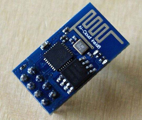
The ESP8266 is a low-cost Wi-Fi microchip with built-in TCP/IP networking software and microcontroller capability. The chip is also not very power-hungry. The ESP8266-01 is also one of the industry's most integrated Wi-Fi chips; it includes an antenna power amplifier, low noise receive amplifier, filters, and power management modules.
ESP-01 Pin Description
|
No. |
Pin Name |
Function |
|
1 |
GND |
GND |
|
2 |
GPIO2 |
GPIO,Internal Pull-up |
|
3 |
GPIO0 |
GPIO,Internal Pull-up |
|
4 |
RX |
UART0,data received pin RXD |
|
5 |
VCC |
3.3V power supply (VDD) |
|
6 |
RST |
External reset pin, active low |
|
7 |
CH_PD |
Chip enable pin. Active high |
|
8 |
TXD |
UART0,data send pin RXD |
Materials Required to build SOnOff Smart Switch
- ESP-01
- Hi-Link Power Supply (5V 0.6A)
- Solid State Relay
- Terminal Block
- Capacitor (100uF, 2.2uf)
- Resistor (100KΩ, 10KΩ, 1KΩ)
- BC557 Transistor
- AMS1117 3.3V Voltage Regulator
- Soldering Kit
- Connecting Wires
- Perf Board
Wi-Fi Smart Switch Circuit Diagram
The hardware for the project requires some simple connections to be made. A voltage regulator to power the ESP-01 and a PNP transistor-based relay driver circuit.
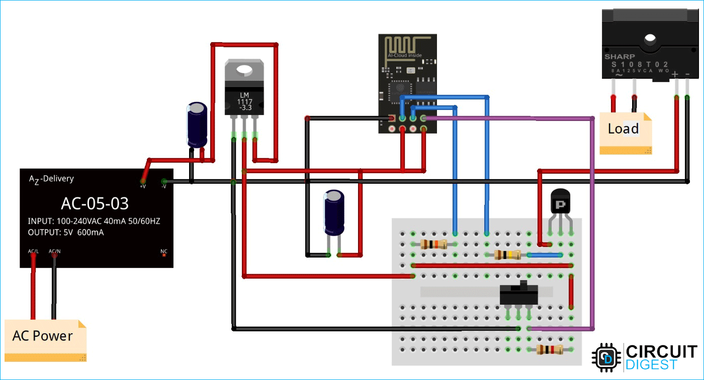
We will be using a Hi-Link (5V 0.6A) module to power everything up. As you know, ESP-01 operates on 3.3V; we will be using an LM1117 3.3V linear voltage regulator and filtering capacitors on both the input and output sides. To power, the ESP-01, connect the output of LM1117 to the Vcc and ground. Also, join the EN pin to Vcc to enable the board. GPIO 0 is pulled high with a 10kΩ resistor. GPIO 2 is connected to the base of the BC557 PNP transistor, whose emitter is connected to +5V, and the collector is connected to the positive line of the relay. Without damaging the ESP-01 at 3.3V, this transistor acts as a switch and allows us to drive a 5V relay using a 3.3V logic microcontroller. GPIO 3 is connected to the toggle switch, and the other end of the switch is connected to the ground. When the switch connects the GPIO 2 to the ground, the load is turned on; GPIO 3 is also pulled high using an inline 1KΩ resistor to bring it back to the high state once the switch is turned off. I have used terminal block to make it safer while connecting the wires.
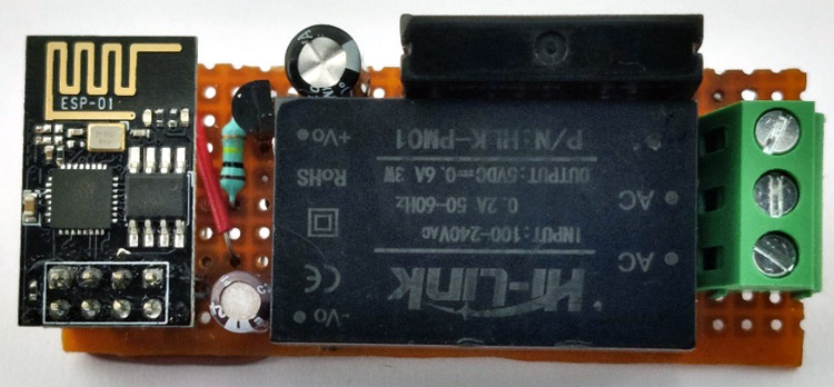
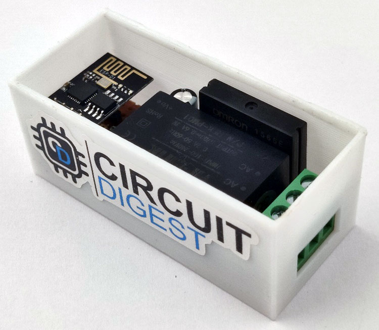
Once you are done with soldering and assembling everything, it should look something like this.
Programming the ESP for Smart Switch
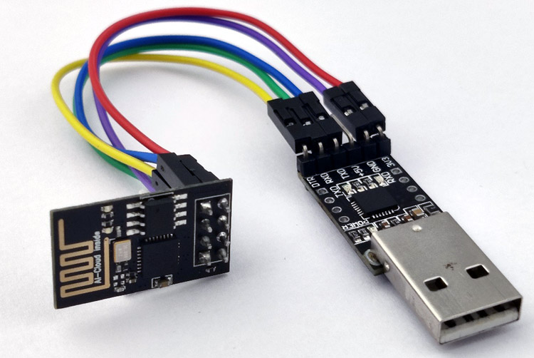
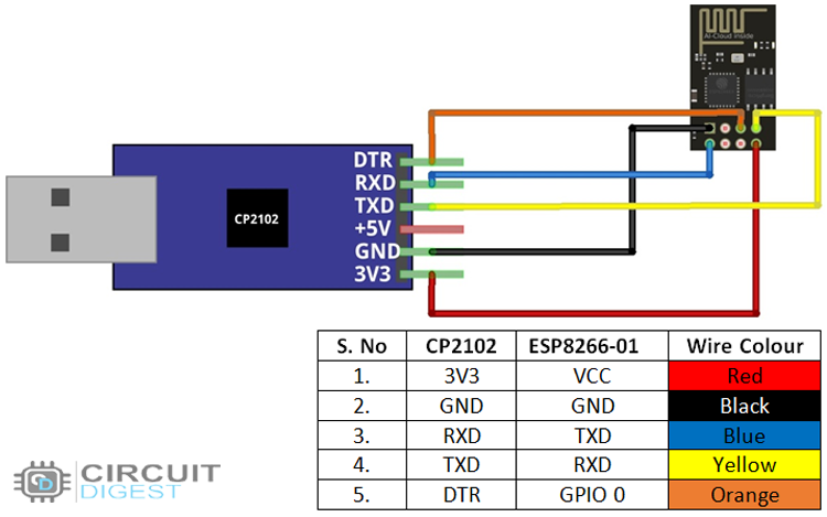
To program the ESP-01 and connect it to the PC, we need a CP2102 USB breakout board. Make the below connection and plug it into the PC.
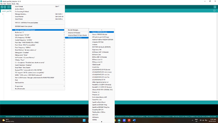
Here you can find more information on how to program the ESP-01 board using Arduino IDE. Make sure the board configuration is same as the below image.
Smart Wi-fi SONOFF Smart Switch Code
Depending on the board, you use different libraries. Here we are using an ESP-01, so we will be using the following library.
For ESP-01, install the ESPAsyncWebServer and the ESPAsyncTCP libraries from github to your Arduino IDE.
#include <ESP8266WiFi.h>
#include <ESPAsyncTCP.h>
#include <ESPAsyncWebServer.h>
Remember to provide your network credentials in the variables below so that the ESP can connect to your network.
const char* ssid = "SSID";
const char* password = "Password";
When the web server first starts, it is set to HIGH. So as to keep the load off when the system is turned on or in case of a power failure.
int ledState = HIGH;
The buttonState and lastButtonState variables are used to determine whether or not the switch has been pressed.
int buttonState;
int lastButtonState = HIGH;
CSS for styling the webpage and buttons-
<style>
    html {font-family: Arial; display: inline-block; text-align: center;}
    h2 {font-size: 3.0rem;}
    p {font-size: 3.0rem;}
    body {max-width: 600px; margin:0px auto; padding-bottom: 25px;}
    .switch {position: relative; display: inline-block; width: 108px; height: 50px}
    .switch input {display: none}
    .slider {position: absolute; top: 0; left: 0; right: 0; bottom: 0; background-color: #ccc; border-radius: 34px}
    .slider:before {position: absolute; content: ""; height: 40px; width: 40px; left: 6px; bottom: 5px; background-color: #fff; -webkit-transition: .4s; transition: .4s; border-radius: 68px}
    input:checked+.slider {background-color: #2196F3}
    input:checked+.slider:before {-webkit-transform: translateX(52px); -ms-transform: translateX(52px); transform: translateX(52px)}
    h4{font-size:28px;}
    #outputState{background:gainsboro;padding:2px 18px;font-size:28px;margin-left:10px;border-radius:3px;}
  </style>
The toggleCheckbox() function is invoked when you push the button. To switch the relay on or off, this method will send requests to several URLs.
function toggleCheckbox(element) {
  var xhr = new XMLHttpRequest();
  if(element.checked){ xhr.open("GET", "/update?state=0", true); }
  else { xhr.open("GET", "/update?state=1", true); }
  xhr.send();
}
To keep the web server's output state updated, we use the following method, which makes a new request to the /state URL every second.
     setInterval(function ( ) {
  var xhttp = new XMLHttpRequest();
  xhttp.onreadystatechange = function() {
    if (this.readyState == 4 && this.status == 200) {
      var inputChecked;
      var outputStateM;
      if( this.responseText == 1){
        inputChecked = false;
        outputStateM = "Off";
      }
      else {
        inputChecked = true;
        outputStateM = "On";
      }
      document.getElementById("output").checked = inputChecked;
      document.getElementById("outputState").innerHTML = outputStateM;
    }
  };
  xhttp.open("GET", "/state", true);
 xhttp.send();
}, 1000 ) ;
Request handling, when the ESP8266-01 receives requests on those URLs, we need to manage it.
When a request for the root / URL is received, we deliver to both the HTML page and the processor.
  server.on("/", HTTP_GET, [](AsyncWebServerRequest *request){
    request->send_P(200, "text/html", index_html, processor);
Converts RX pin to GPIO 3. Because RX is now a GPIO pin and does not transmit Serial data, you will no longer be able to use the Serial Monitor.
pinMode(3, FUNCTION_3);
  pinMode(3, OUTPUT);
Enables the ESP to turn the load on or off, by detecting the Realtime position of the switch. Because we are using a PNP transistor when the GPIO goes HIGH, the transistor stops conducting which turns the relay off and when the GPIO goes LOW, the transistor starts conducting which in turn turns the relay on.
  if(digitalRead(buttonPin)==0)
        digitalWrite(output, HIGH);
        else
        if(digitalRead(buttonPin)==1)
        digitalWrite(output, LOW);
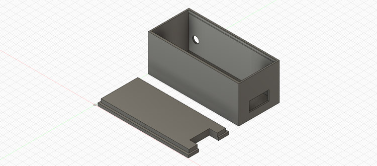
3D Printed Enclosure for Compact Smart Switch
Since the project handles AC and is needed to be placed inside a switchboard, it’s not safe to just place the circuit inside. To overcome this, I designed an enclosure in fusion 360 after taking the dimension of the device, with appropriate cut-outs to make the connections.
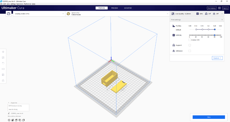
Then to get it ready for 3D printing I sliced it through Ultimake Cura.
Once its done 3D printing, you will have something like this with you. All that’s left to do is to place the device inside the enclosure.

Once assembled it looks something like this.
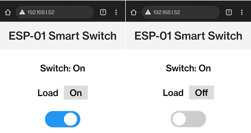
Testing Wireless Smart Switch
CONCLUSION
An ESP-based device was created to convert any standard switch into a smart switch.
You can also check out the demonstration video given below and if you have any doubt you can ask in the comment section below or use our Forum for technical discussion.
Complete Project Code
#include <ESP8266WiFi.h>

#include <ESPAsyncTCP.h>

#include <ESPAsyncWebServer.h>

const char* ssid = "SSID";

const char* password = "PASSWORD";

const char* PARAM_INPUT_1 = "state";

const int output = 2 ;

const int buttonPin = 3;

int ledState = HIGH;          // the current state of the output pin

int buttonState;             // the current reading from the input pin

int lastButtonState = HIGH;   // the previous reading from the input pin

unsigned long lastDebounceTime = 0;  // the last time the output pin was toggled

unsigned long debounceDelay = 10;    // the debounce time; increase if the output flickers

AsyncWebServer server(80);

const char index_html[] PROGMEM = R"rawliteral(

<!DOCTYPE HTML><html>

<head>

  <title>ESP Web Server</title>

  <meta name="viewport" content="width=device-width, initial-scale=1">

  <style>

    html {font-family: Arial; display: inline-block; text-align: center;}

    h2 {font-size: 3.0rem;}

    p {font-size: 3.0rem;}

    body {max-width: 600px; margin:0px auto; padding-bottom: 25px;}

    .switch {position: relative; display: inline-block; width: 108px; height: 50px}

    .switch input {display: none}

    .slider {position: absolute; top: 0; left: 0; right: 0; bottom: 0; background-color: #ccc; border-radius: 34px}

    .slider:before {position: absolute; content: ""; height: 40px; width: 40px; left: 6px; bottom: 5px; background-color: #fff; -webkit-transition: .4s; transition: .4s; border-radius: 68px}

    input:checked+.slider {background-color: #2196F3}

    input:checked+.slider:before {-webkit-transform: translateX(52px); -ms-transform: translateX(52px); transform: translateX(52px)}

    h4{font-size:28px;}

    #outputState{background:gainsboro;padding:2px 18px;font-size:28px;margin-left:10px;border-radius:3px;}

  </style>

</head>

<body>

  <h2 style="font-size:34px;color:#222;text-align:center; background-color:#f3f3f3;margin:0 0 30px 0;padding:20px 0;">ESP-01 Smart Switch</h2>

  <div style="font-size:28px;">

  </div>

  %BUTTONPLACEHOLDER%

<script>function toggleCheckbox(element) {

  var xhr = new XMLHttpRequest();

  if(element.checked){ xhr.open("GET", "/update?state=0", true); }

  else { xhr.open("GET", "/update?state=1", true); }

  xhr.send();

}

setInterval(function ( ) {

  var xhttp = new XMLHttpRequest();

  xhttp.onreadystatechange = function() {

    if (this.readyState == 4 && this.status == 200) {

      var inputChecked;

      var outputStateM;

      if( this.responseText == 1){

        inputChecked = false;

        outputStateM = "Off";

      }

      else {

        inputChecked = true;

        outputStateM = "On";

      }

      document.getElementById("output").checked = inputChecked;

      document.getElementById("outputState").innerHTML = outputStateM;

    }

  };

  xhttp.open("GET", "/state", true);

  xhttp.send();

}, 1000 ) ;

</script>

</body>

</html>

)rawliteral";

String processor(const String& var){

  if(var == "BUTTONPLACEHOLDER"){

    String buttons ="";

    String outputStateValue = outputState();

    if(buttonState){

    buttons+= "<h4>Switch: On </h4>";

    }

    else{

    buttons+= "<h4>Switch: Off </h4>";

    }

    buttons+= "<h4>Load <span id=\"outputState\"></span></h4><label class=\"switch\"><input type=\"checkbox\" onchange=\"toggleCheckbox(this)\" id=\"output\" " + outputStateValue + "><span class=\"slider\"></span></label>";

    return buttons;

  }

  return String();

}

String outputState(){

  if(digitalRead(output)==0){

    return "checked";

  }

  else {

    return "";

  }

  return "";

}

void setup(){

  pinMode(3, FUNCTION_3);

  pinMode(3, OUTPUT);

  pinMode(output, OUTPUT);

  digitalWrite(output, HIGH);

  pinMode(buttonPin, INPUT);

  WiFi.begin(ssid, password);

  while (WiFi.status() != WL_CONNECTED) {

    delay(1000);

    Serial.println("Connecting to WiFi..");

  }

  Serial.println(WiFi.localIP());

  server.on("/", HTTP_GET, [](AsyncWebServerRequest *request){

    request->send_P(200, "text/html", index_html, processor);

  });

  server.on("/update", HTTP_GET, [] (AsyncWebServerRequest *request) {

    String inputMessage;

    String inputParam;

    if (request->hasParam(PARAM_INPUT_1)) {

      inputMessage = request->getParam(PARAM_INPUT_1)->value();

      inputParam = PARAM_INPUT_1;

      digitalWrite(output, inputMessage.toInt());

      ledState = !ledState;

    }

    else {

      inputMessage = "No message sent";

      inputParam = "none";

    }

    Serial.println(inputMessage);

    request->send(200, "text/plain", "OK");

  });

  server.on("/state", HTTP_GET, [] (AsyncWebServerRequest *request) {

    request->send(200, "text/plain", String(digitalRead(output)).c_str());

  });

  server.begin();

}

void loop() {

  int reading = digitalRead(buttonPin);

  if (reading != lastButtonState) {

    lastDebounceTime = millis();

  }

  if ((millis() - lastDebounceTime) > debounceDelay) {

    if (reading != buttonState) {

      buttonState = reading;

        if(digitalRead(buttonPin)==0)

        digitalWrite(output, HIGH);

        else

        if(digitalRead(buttonPin)==1)

        digitalWrite(output, LOW);

      }

    }

    lastButtonState = reading;

  }
Comments
Hello I am elouazani, can you help me to simulate this circuit , on matlab if possible

Hello, my name is Alif. I am a student in Malaysia currently studying computer information and would like to ask about your project. I'm having issues with your circuit. I can't really understand the diagram as I'm not very good at reading them. I hope you can make a video showing step-by-step how to assemble it.