

Generally, the LM35 temperature sensor is used with microcontrollers to measure the temperature because it is cheap and easily available. But LM35 gives analog values and we need to convert them into digital using ADC (Analog to Digital Converter). But today we are using DS18B20 temperature sensor in which we don’t need an ADC conversion to get the temperature. Here we will use PIC Microcontroller with DS18B20 to measure the Temperature.
So here we are building a Thermometer with the following specification using PIC16F877A microcontroller unit from microchip.
- It will show Full range of temperature from -55 degree to +125 degree.
- It will only display the temperature if temperature changes + / - .2 degree.
Components Required:-
- Pic16F877A – PDIP40 package
- Bread Board
- Pickit-3
- 5V adapter
- LCD JHD162A
- DS18b20 temperature sensor
- Wires to connect peripherals.
- 4.7k Resistors – 2pcs
- 10k pot
- 20mHz Crystal
- 2 pcs 33pF ceramic capacitors
DS18B20 Temperature Sensor:
DS18B20 is an excellent sensor to accurately sense the temperature. This sensor provide 9bit to 12bit resolution on temperature sensing. This sensor communicates with only one wire and does not need any ADC to acquire analog temperatures and converting them in digitally.
The specification of the sensor is:-
- Measures Temperatures from -55°C to +125°C (-67°F to +257°F)
- ±0.5°C Accuracy from -10°C to +85°C
- Programmable Resolution from 9 Bits to 12 Bits
- No External Components Required
- The sensor use 1-Wire® Interface
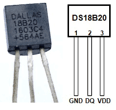
If we look at above pinout image from datasheet, we can see that the sensor looks exactly same like BC547 or BC557 package, TO-92. The first pin is Ground, Second pin is DQ or the data and the Third pin is VCC.
Below is the electrical specification from Datasheet which will be needed for our design. The rated supply voltage for the sensor is +3.0V to +5.5V. It’s also need pull up supply voltage which is same as the supply voltage stated above.
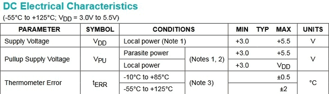
Also, there is an accuracy margin which is +-0.5 degree Celsius for the range of -10 Degree C to +85 Degree Celsius, and the accuracy changes for the full range margin, which is +-2 Degree for -55 Degree to +125 Degree range.
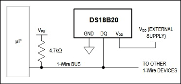
If we again look at the datasheet, we will see the connection specification of the sensor. We can connect the sensor in parasitic power mode where two wires are needed, DATA and GND, or we can connect the sensor using external power supply, where three separate wires are needed. We will use the second configuration.
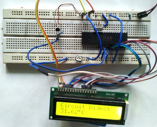
As we are now familiar with the power ratings of the sensor and connection related areas, we can now concentrate on making the schematic.
Circuit diagram:-

If we see the circuit diagram we will see that:-
16x2 character LCD is connected across PIC16F877A microcontroller, in which RB0, RB1, RB2 are connected to LCD pin RS, R/W , and E. And RB4, RB5, RB6 and RB7 are connected across LCD’s 4 pin D4, D5, D6, D7. The LCD is connected in 4bit mode or nibble mode.
A crystal Oscillator of 20MHz with two ceramic capacitor of 33pF is connected across OSC1 and OSC2 pin. It will provide constant 20Mhz clock frequency to the microcontroller.
DS18B20 is also connected as per the pin configuration and with a 4.7k pull up resistor as discussed before. I have connected all this in the breadboard.
If you are new to PIC Microcontroller than follow our PIC Microcontroller Tutorials stating with Getting started with PIC Microcontroller.
Steps or code flow:-
- Set the configurations of the microcontroller which include Oscillator configuration.
- Set the Desired port for LCD including TRIS register.
- Every cycle with ds18b20 sensor start with reset, so we will reset the ds18b20 and wait for the presence pulse.
- Write the scratchpad and set the resolution of the sensor 12bit.
- Skip the ROM read followed by a reset pulse.
- Submit convert temperature command.
- Read the temperature from the scratchpad.
- Check the temperature value whether negative or positive.
- Print the temperature on 16x2 LCD.
- Wait for the temperature changes for +/-.20 degree Celsius.

Code Explanation:
Full code for this Digital Thermometer is given at the end of this tutorial with a Demonstration Video. You will be needing some header files to run this program which can be downloaded from here.
First, we need to set the configuration bits in the pic microcontroller and then start with void main function.
Then below four lines are used for including library header file, lcd.h and ds18b20.h. And xc.h is for microcontroller header file.
#include <xc.h>
#include <string.h>
#include "supporting c files/ds18b20.h"
#include "supporting c files/lcd.h"
These definitions are used for sending command to the temperature sensor. The commands are listed in the sensor’s datasheet.
#define        skip_rom 0xCC
#define      convert_temp 0x44
#define      write_scratchpad 0x4E
#define      resolution_12bit 0x7F
#define        read_scratchpad 0xBE
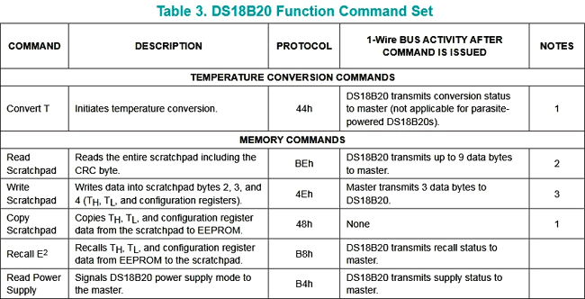
This Table 3 from the sensor’s datasheet is showing all commands where macros are used to sending respective commands.
The temperature will only display in the screen if the temperature changes +/- .20 degree. We can change this temperature gap from this temp_gap macro. By changing the value at this macro, the specification will be changed.
Other two float variables used for storing the displayed temperature data and differentiate them with the temperature gap
#define temp_gap  20
float pre_val=0, aft_val=0;
.
In void main() function, the lcd_init(); is a function to initialize LCD. This lcd_init() function is called from the lcd.h library.
TRIS registers are used to select I/O pins as input or output. Two unsigned short variable TempL and TempH are used for storing the 12bit resolution data from temperature sensor.
void main(void) {
    TRISD = 0xFF;
    TRISA = 0x00;
    TRISB = 0x00;
    //TRISDbits_t.TRISD6 = 1;
    unsigned short TempL, TempH;
                   unsigned int t, t2;
                   float difference1=0, difference2=0;
    lcd_init();
Let’s see the while loop, here we are breaking the while(1) loop into small chunks.
Those lines are used to sense the temperature sensor is connected or not.
while(ow_reset()){
                                    lcd_com(0x80);
                                    lcd_puts ("Please Connect   ");
                                    lcd_com (0xC0);
                                    lcd_puts("Temp-Sense Probe");
                        }
By using this segment of code we initialize the sensor and send command to convert the temperature.
lcd_puts ("                ");
                        ow_reset();
                        write_byte(write_scratchpad);
                        write_byte(0);
                        write_byte(0);
                        write_byte(resolution_12bit); // 12bit resolution
                        ow_reset();
                        write_byte(skip_rom);
                        write_byte(convert_temp);
This code is for storing the 12bit temperature data in two unsigned short variables.
                   while (read_byte()==0xff);
                                    __delay_ms(500);
                                    ow_reset();
                                    write_byte(skip_rom);
                                    write_byte(read_scratchpad);
                                    TempL = read_byte();
                                    TempH = read_byte();
Then if you check the complete code below, we have create if-else condition to find out the temperature sign whether it is positive or negative.
By using the If statement code, we manipulate the data and see whether the temperature is negative or not and determine the temperature changes is in +/- .20 degree range or not. And in else part we checked whether the temperature is positive or not and temperature changes detection.
code
Getting Data from DS18B20 Temperature Sensor:
Let’s see the time gap of 1-Wire® Interface. We are using 20Mhz Crystal. If we look inside the ds18b20.c file, we will see
#define _XTAL_FREQ 20000000
This definition is used for XC8 compiler delay routine. 20Mhz is set as the crystal frequency.
We made five functions
- ow_reset
- read_bit
- read_byte
- write_bit
- write_byte
1-Wire® protocol needs strict timing related slots to communicate. Inside the datasheet, we will get perfect time-slot related information.
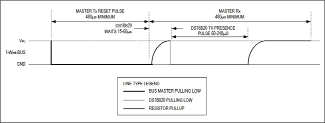
Inside the below function we created the exact time slot. It is important to create the exact delay for hold and release and control the TRIS bit of the respective sensor’s port.
unsigned char ow_reset(void)
{
    DQ_TRIS = 0; // Tris = 0 (output)
            DQ = 0; // set pin# to low (0)
            __delay_us(480); // 1 wire require time delay
            DQ_TRIS = 1; // Tris = 1 (input)
            __delay_us(60); // 1 wire require time delay

                        if (DQ == 0) // if there is a presence pluse
                        {
                        __delay_us(480);
                        return 0; // return 0 ( 1-wire is presence)
                        }
                        else
                        {
                        __delay_us(480);
                        return 1; // return 1 ( 1-wire is NOT presence)
                        }
} // 0=presence, 1 = no part
Now as per the below time slot description used in Read and Write, we created the read and write function respectively.
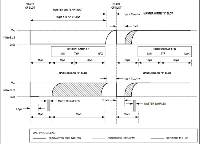
unsigned char read_bit(void)
{
            unsigned char i;
            DQ_TRIS = 1;
    DQ = 0; // pull DQ low to start timeslot
            DQ_TRIS = 1;
    DQ = 1; // then return high
            for (i=0; i<3; i++); // delay 15us from start of timeslot
            return(DQ); // return value of DQ line
}

void write_bit(char bitval)
{
            DQ_TRIS = 0;
    DQ = 0; // pull DQ low to start timeslot
            if(bitval==1) DQ =1; // return DQ high if write 1
            __delay_us(5); // hold value for remainder of timeslot
    DQ_TRIS = 1;
            DQ = 1;
}// Delay provides 16us per loop, plus 24us. Therefore delay(5) = 104us
Further check all the related header and .c files here.
So this is how we can use DS18B20 sensor to get the temperature with PIC Microcontroller.
If you want to build a simple Digital Thermometer with LM35, checkout below projects with other Microcontrollers:
Complete Project Code
/*
 * File:   main.c
 * Author: Sourav Gupta
 *
 * Created on 11 April 2018, 17:57
 */

/*
 * Configuration Related settings. Specific for microcontroller unit.
 */
#pragma config FOSC = HS        // Oscillator Selection bits (HS oscillator)
#pragma config WDTE = OFF       // Watchdog Timer Enable bit (WDT disabled)
#pragma config PWRTE = OFF      // Power-up Timer Enable bit (PWRT disabled)
#pragma config BOREN = ON       // Brown-out Reset Enable bit (BOR enabled)
#pragma config LVP = OFF         // Low-Voltage (Single-Supply) In-Circuit Serial Programming Enable bit (RB3/PGM pin has PGM function; low-voltage programming enabled)
#pragma config CPD = OFF        // Data EEPROM Memory Code Protection bit (Data EEPROM code protection off)
#pragma config WRT = OFF        // Flash Program Memory Write Enable bits (Write protection off; all program memory may be written to by EECON control)
#pragma config CP = OFF         // Flash Program Memory Code Protection bit (Code protection off)
#define _XTAL_FREQ 20000000
/*
 * System Header files inclusions
 */

#include <xc.h>
#include <string.h>
#include "supporting c files/ds18b20.h"
#include "supporting c files/lcd.h"

/*
 * Ds18b20 related definition
 */

#define skip_rom 0xCC
#define convert_temp 0x44
#define write_scratchpad 0x4E
#define resolution_12bit 0x7F
#define read_scratchpad 0xBE

/*
 * User interface related definitions
 */

#define temp_gap  20

float pre_val=0, aft_val=0;

/*
 * Program flow related functions
 */

void sw_delayms(unsigned int d);

/* Main function / single Thread*/
void main(void) {
    TRISD = 0xFF;
    TRISA = 0x00;
    TRISB = 0x00;
    //TRISDbits_t.TRISD6 = 1;
    unsigned short TempL, TempH;
unsigned int t, t2;
float difference1=0, difference2=0;
    lcd_init();
    while(1){
        float i=0;
/* This is for presence detection of temp-sensing probe*/
while(ow_reset()){
lcd_com(0x80);
lcd_puts ("Please Connect   ");
lcd_com (0xC0);
lcd_puts("Temp-Sense Probe");
}
/*------------------------------------------------------*/

        lcd_puts ("                ");
ow_reset();
write_byte(write_scratchpad);
    write_byte(0);
write_byte(0);
write_byte(resolution_12bit); // 12bit resolution
ow_reset();
write_byte(skip_rom);
write_byte(convert_temp);

while (read_byte()==0xff);
__delay_ms(500);
ow_reset();

write_byte(skip_rom);
write_byte(read_scratchpad);

TempL = read_byte();
TempH = read_byte();

/*This is for Negative temperature*/

/*If result  (TempH [Bitwise and] 1000 0000) = not 0
     *then this condition get true.
case1. -0.5 degree value = 1111 1111. [1111 1111 & 1000 0000 = 1000 0000 which is not 0.]
case2. -55 degree value = 1111 1100. [1111 1100 & 1000 0000 = 1000 0000 which is not 0]
0x80 = 1000 0000
Test Case -10.125  output 1111 1111 0101 1110*/

if((TempH & 0x80)!=0){    // If condition will execute as TempH = 1111 1111 & 1000 0000 = 1000 0000.
t=TempH;// Store tempH value in t = 1111 1111  .
        t<<=8;//after bitwise left shift 8 times value in t will be 1111 1111 0000 0000.
        t=t|TempL;// t = 1111 1111 0000 0000 | 0101 1110 [ result t = 1111 1111 0101 1110]
        t=t-1;//t = t-1 in this case t = 1111 1111 0101 1101.
        t=~t;// t = 0000 0000 1010 0010.
        t>>=4;// t = 0000 0000 0000 1010.
t=t*100;// t = 10 * 100 = 1000.
t2=TempL; //Store tempL value = 0101 1110.
t2=t2-1;// t2= 0101 1101
        t2=~t2;//t2 = 1010 0010
        t2=t2&0x0f;// t2 = 1010 0010 | 0000 1111 = 0000 0010
t2=t2 * 6.25; // 0000 00010 = 2 x 6.25 = 12.50
i=((unsigned int)t ) + (unsigned int)t2; //put both value in one variable 1000 + 12.5 = 1012.5

/*This if-else condition done because LCD would not refresh till temperature change -.20 or +.20 degree*/

pre_val=aft_val;

difference1 = pre_val - i;
difference2 = i - pre_val;

if(difference1 > temp_gap || difference2 > temp_gap){
aft_val = i;
lcd_com (0x80);
lcd_puts ("Circuit Digest");
lcd_com (0xc0);
lcd_puts("-");
lcd_bcd (5,aft_val);
lcd_data(223);
lcd_puts("C    ");
}
else{
lcd_com (0x80);
lcd_puts ("Circuit Digest");
lcd_com (0xc0);
lcd_puts("-");
lcd_bcd (5,pre_val);
lcd_data(223);
lcd_puts("C    ");


}
}
/*This is for positive Temperature*/
else {
i=((unsigned int)TempH << 8 ) + (unsigned int)TempL; //put both value in one variable
i = i * 6.25;   //calculations used from the table provided in the data sheet of ds18b20

/*This if-else condition done because LCD would not refresh till temperature change -.20 or +.20 degree*/
pre_val=aft_val;

difference1 = pre_val - i;
difference2 = i - pre_val;

if(difference1 > temp_gap || difference2 > temp_gap){
aft_val = i;
lcd_com (0x80);
lcd_puts ("Circuit Digest");
lcd_com (0xc0);
lcd_bcd (5,aft_val);
lcd_data(223);
lcd_puts("C    ");

}
else{
lcd_com (0x80);
lcd_puts ("Circuit Digest");
lcd_com (0xc0);
lcd_bcd (5,pre_val);
lcd_data(223);
lcd_puts("C    ");
}
        }
    }
    return;
}

void sw_delayms(unsigned int d){
int x, y;
for(x=0;x<d;x++)
for(y=0;y<=1275;y++);
}
Comments
good tutorial. Spend nearly one day to fix it and make it work. Basic read and write function works. read function needs to add delay .
Good job man.

hi. I try to simulate the code but it didn't work first time.
then I go through all data sheet and changed some part of the code . then succeed to run termometer on lcd. I also edit a bit header files lcd.h and also ds18b20.h .
it toke me a long time but good practice . my opinion about interfacing with this sensor and using it in real project is that its slow to respond to temperature changes because it has to through a procedure of sending and receiving data via 1-wire cable and we use __delay... function a lot of time to read and write.
and last ialways have question from the person who write the code why he want to use for loop to create delay where we can use __delay_us() and __delay_ms() . its so complecated to me to figure out how many instruction cycle should i count to get delay value by using for loop. easier to use __delay.. function .any one else done this project please share idea thanks