

Temperature and Humidity measurement is often useful in many applications like Home Automation, Environment Monitoring, Weather station, etc. The most popularly used Temperature sensor next to LM35 is the DHT11, we have previously built many DHT11 Projects by interfacing it with Arduino, with Raspberry Pi and many other development boards. In this article, we will learn how to interface this DHT11 with PIC16F87A which is an 8-bit PIC Microcontroller. We will use this microcontroller to read the values of Temperature and Humidity using DHT11 and display it on an LCD display. If you are completely new with using PIC microcontrollers you can make use of our PIC tutorial series to learn how to program and use PIC microcontroller, that being said, let's get started.
DHT11 – Specification and Working
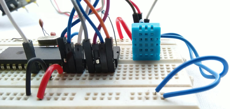
The DHT11 sensor is available either in module form or in sensor form. In this tutorial we are using the sensor, the only difference between the both is that in module form the sensor has a filtering capacitor and a pull-up resistor attached to the output pin of the sensor. So if you are using the module you need not add them externally. The DHT11 in sensor form is shown below.
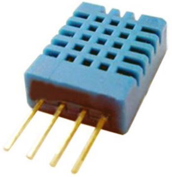
The DHT11 sensor comes with a blue or white color casing. Inside this casing, we have two important components that help us to sense the relative humidity and temperature. The first component is a pair of electrodes; the electrical resistance between these two electrodes is decided by a moisture-holding substrate. So the measured resistance is inversely proportional to the relative humidity of the environment. Higher the relative humidity lower will be the value of resistance and vice versa. Also, note that Relative humidity is different from actual humidity. Relative humidity measures the water content in the air relative to the temperature in the air.
The other component is a surface mounted NTC Thermistor. The term NTC stands for the Negative temperature coefficient, for the increase in temperature the value of resistance will decrease. The output of the sensor is factory calibrated and hence as a programmer we need not worry about calibrating the sensor. The output of the sensor given by 1-Wire communication, let's see the pin and connection diagram of this sensor.
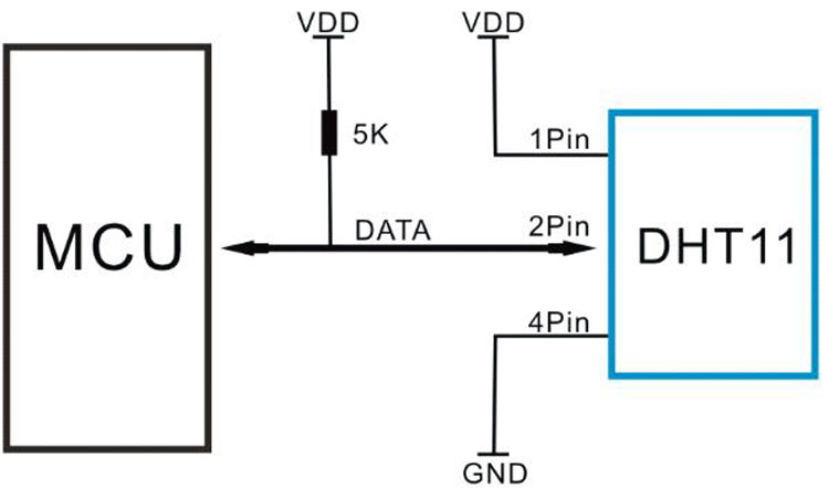
The product is in a 4pin single row package. 1st pin is connected across the VDD and the 4th pin is connected across the GND. The 2nd pin is the data pin, used for communication purposes. This data pin needs a pull-up resistor of 5k. However, others pull up resistors such as 4.7k to the 10k can also be used. The 3rd pin is not connected with anything. So it is ignored.
The datasheet provides technical specifications as well as interfacing information that can be seen in the below table-
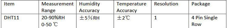
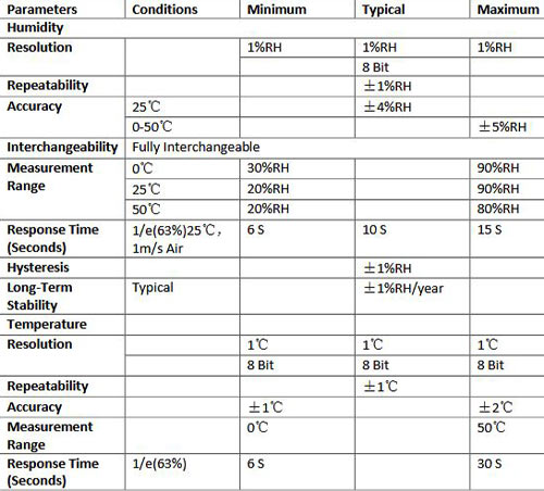
The above table is showing Temperature and Humidity measurement range and accuracy. It can measure temperature from 0-50 degrees Celsius with an accuracy of +/- 2-degree Celsius and relative humidity from 20-90%RH with an accuracy of +/- 5%RH. The detail specification can be seen in the below table.
Communicating with DHT11 Sensor
As mentioned earlier, in order to read the data from DHT11 with PIC we have to use PIC one wire Communication protocol. The details on how to perform this can be understood from the interfacing diagram of DHT 11 which can be found in its datasheet, the same is given below.
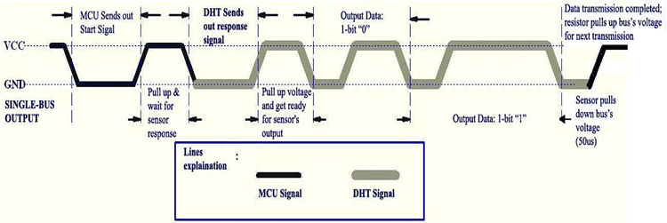
DHT11 needs a start signal from the MCU to start the communication. Therefore, every time the MCU needs to send a start signal to the DHT11 Sensor to request it to send the values of temperature and humidity. After completing the start signal, the DHT11 sends a response signal which includes the temperature and humidity information. The data communication is done by the single bus data communication protocol. The full data length is 40bit and the sensor sends higher data bit first.
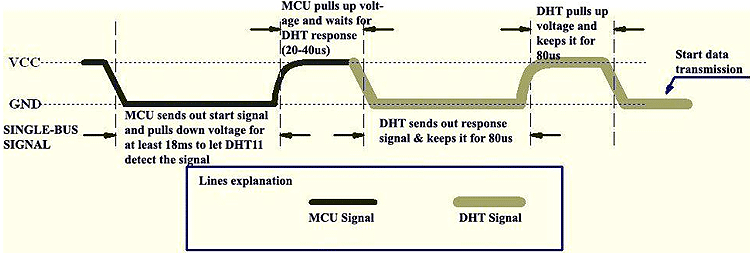
Due to the pull-up resistor, the data line always remains at the VCC level during idle mode. The MCU needs to pull down this voltage high to low for a minimum span of 18ms. During this time, the DHT11 sensor detects the start signal and the microcontroller makes the data line high for 20-40us. This 20-40us time is called a waiting period where the DHT11 starts to the response. After this waiting period, DHT11 sends the data to the microcontroller unit.
DHT11 Sensor DATA Format
The data consists of decimal and integral parts combined together. The sensor follows the below data format –
8bit integral RH data + 8bit decimal RH data + 8bit integral T data + 8bit decimal T data + 8bit checksum.
One can verify the data by checking the checksum value with the received data. This can be done because, if everything is proper and if the sensor has transmitted proper data, then the checksum should be the sum of “8bit integral RH data+8bit decimal RHdata+8bit integral T data+8bit decimal T data”.
Required components
For this project, below things are required -
- PIC microcontroller (8bit) programming setup.
- Breadboard
- 5V 500mA power supply unit.
- 4.7k resistor 2pcs
- 1k resistor
- PIC16F877A
- 20mHz crystal
- 33pF capacitor 2 pcs
- 16x2 character LCD
- DHT11 sensor
- Jumper wires
Schematic
The circuit diagram for interfacing DHT11 with PIC16F877A is shown below.

We have used a 16x2 LCD to display the temperature and humidity values that we measure from DHT11. The LCD is interfaced in 4-wire mode and both the sensor and LCD are powered by a 5V external power supply. I have used a breadboard to make all the required connections and have used an external 5V adapter. You can also use this breadboard power supply board to power your board with 5V.
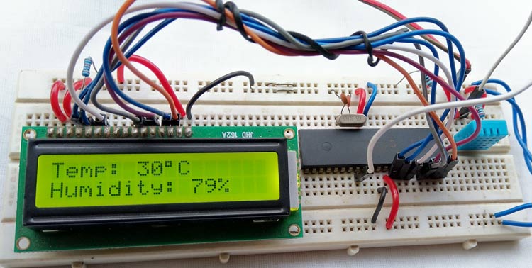
Once the circuit is ready, all we have to do is upload the code given at the bottom of this page and we can start reading the Temperature and Humidity like shown below. If you want to know how the code was written and how it works read further. Also you can find the complete working of this project in the video given at the bottom of this page.

DHT11 with PIC MPLABX Code explanation
The code was written using MPLABX IDE and compiled using the XC8 compiler both of which provided by Microchip itself and is free to download and use. Please refer to the basic tutorials to understand the basics of programming, only the three important functions which are required for communicating with the DHT11 sensor is discussed below. The functions are -
void dht11_init();
void find_response();
char read_dht11();
The first function is used for the start signal with dht11. As discussed before, every communication with DHT11 starts with a start signal, here the pin direction is changed at first to configure the data pin as output from the microcontroller. Then the data line is pulled low and keeps waiting for the 18mS. After that again the line is made high by the microcontroller and keeps waiting for up to 30us. After that waiting time, the data pin set as input to the microcontroller to receive the data.
void dht11_init(){
 DHT11_Data_Pin_Direction= 0; //Configure RD0 as output
 DHT11_Data_Pin = 0; //RD0 sends 0 to the sensor
 __delay_ms(18);
 DHT11_Data_Pin = 1; //RD0 sends 1 to the sensor
 __delay_us(30);
 DHT11_Data_Pin_Direction = 1; //Configure RD0 as input
 }
The next function is used for setting up a check bit depending on the data pin status. It is used to detect the response from DHT11 sensor.
 void find_response(){
 Check_bit = 0;
 __delay_us(40);
 if (DHT11_Data_Pin == 0){
 __delay_us(80);
 if (DHT11_Data_Pin == 1){
            Check_bit = 1;
 }
 __delay_us(50);}
 }
Finally the dht11 read function; here the data is read into an 8-bit format where the data is returned using bit shift operation depending on the data pin status.
char read_dht11(){
char data, for_count;
for(for_count = 0; for_count < 8; for_count++){
            while(!DHT11_Data_Pin);
            __delay_us(30);
            if(DHT11_Data_Pin == 0){
            data&= ~(1<<(7 - for_count)); //Clear bit (7-b)
            }
            else{
            data|= (1 << (7 - for_count)); //Set bit (7-b)
            while(DHT11_Data_Pin);
            }
            }
return data;
}
After that, everything is done into the main function. First, the system initialization is done where the LCD is initialized and the LCD pins port direction is set to the output. The application is running inside the main function
void main() {
 system_init();
 while(1){
            __delay_ms(800);
            dht11_init();
            find_response();
            if(Check_bit == 1){
            RH_byte_1 = read_dht11();
            RH_byte_2 = read_dht11();
            Temp_byte_1 = read_dht11();
            Temp_byte_2 = read_dht11();
            Summation = read_dht11();
            if(Summation == ((RH_byte_1+RH_byte_2+Temp_byte_1+Temp_byte_2) & 0XFF)){
            Humidity = Temp_byte_1;
            RH = RH_byte_1;
            lcd_com (0x80);
            lcd_puts("Temp: ");
            //lcd_puts("                 ");
            lcd_data(48 + ((Humidity / 10) % 10));
            lcd_data(48 + (Humidity % 10));
            lcd_data(0xDF);
            lcd_puts("C   ");
            lcd_com (0xC0);
            lcd_puts("Humidity: ");
            //lcd_puts("                 ");
            lcd_data(48 + ((RH / 10) % 10));
            lcd_data(48 + (RH % 10));
            lcd_puts("%  ");
            }
            else{
            lcd_puts("Checksum error");
            }
            }
            else {
            clear_screen();
            lcd_com (0x80);
            lcd_puts("Error!!!");
            lcd_com (0xC0);
            lcd_puts("No Response.");
            }
            __delay_ms(1000);
 }
}
The communication with the DHT11 sensor is done inside the while loop where the start signal is submitted to the sensor. After that, the find_response function is triggered. If the Check_bit is 1 then the further communication is carried otherwise the LCD will show error dialog.
Depending on the 40bit data, the read_dht11 is called 5 times (5 times x 8bit) and stored the data as per the data format provided in the datasheet. The checksum status is also checked and if errors are found, it will also notify in the LCD. Finally, the data is converted and transmitted to the 16x2 character LCD.
Complete code for this PIC Temperature and Humidity measurement can be downloaded from here. Also check the demonstration video given below.
Hope you understood the project and enjoyed building something useful. If you have any questions leave them in the comment section below or use our forums for other technical questions.
Complete Project Code
#include <xc.h>
#include <stdint.h>
#include "supporing_cfile/lcd.h"
#pragma config FOSC = HS        // Oscillator Selection bits (HS oscillator)
#pragma config WDTE = OFF       // Watchdog Timer Enable bit (WDT disabled)
#pragma config PWRTE = ON       // Power-up Timer Enable bit (PWRT enabled)
#pragma config BOREN = ON       // Brown-out Reset Enable bit (BOR enabled)
#pragma config LVP = OFF        // Low-Voltage (Single-Supply) In-Circuit Serial Programming Enable bit (RB3 is digital I/O, HV on MCLR must be used for programming)
#pragma config CPD = OFF        // Data EEPROM Memory Code Protection bit (Data EEPROM code protection off)
#pragma config WRT = OFF        // Flash Program Memory Write Enable bits (Write protection off; all program memory may be written to by EECON control)
#pragma config CP = OFF         // Flash Program Memory Code Protection bit (Code protection off)
/*
 Program Flow related definition
 */
#define DHT11_Data_Pin   PORTDbits.RD5
#define DHT11_Data_Pin_Direction  TRISDbits.TRISD5
#define FIRST_LINE 0x80
#define SECOND_LINE 0xC0
#define _XTAL_FREQ 20000000 //20 Mhz
unsigned char Check_bit, Temp_byte_1, Temp_byte_2, RH_byte_1, RH_byte_2;
unsigned char Himudity, RH, Sumation ;
//Dht11 related definition
void dht11_init();
void find_response();
char read_dht11();
// System related definitions
void system_init(void);
void introduction_screen(void);
void clear_screen(void);
void main() {
 system_init();
 while(1){
     __delay_ms(800);
    dht11_init();
    find_response();
    if(Check_bit == 1){
        RH_byte_1 = read_dht11();
        RH_byte_2 = read_dht11();
        Temp_byte_1 = read_dht11();
        Temp_byte_2 = read_dht11();
        Sumation = read_dht11();
        if(Sumation == ((RH_byte_1+RH_byte_2+Temp_byte_1+Temp_byte_2) & 0XFF)){
            Himudity = Temp_byte_1;
            RH = RH_byte_1;
            lcd_com (0x80);
            lcd_puts("Temp: ");
            //lcd_puts("                ");
            lcd_data(48 + ((Himudity / 10) % 10));
            lcd_data(48 + (Himudity % 10));
            lcd_data(0xDF);
            lcd_puts("C   ");
            lcd_com (0xC0);
            lcd_puts("Humidity: ");
             //lcd_puts("                ");
            lcd_data(48 + ((RH / 10) % 10));
            lcd_data(48 + (RH % 10));
            lcd_puts("%  ");
            }
        else{
            lcd_puts("Check sum error");
        }
    }
    else {
        clear_screen();
        lcd_com (0x80);
        lcd_puts("Error!!!");
        lcd_com (0xC0);
        lcd_puts("No Response.");
     }
    __delay_ms(1000);
 }
}
/*
 * This will initialize the dht22 sensor.
 */
void dht11_init(){
 DHT11_Data_Pin_Direction= 0; //Configure RD0 as output
 DHT11_Data_Pin = 0; //RD0 sends 0 to the sensor
 __delay_ms(18);
 DHT11_Data_Pin = 1; //RD0 sends 1 to the sensor
 __delay_us(30);
 DHT11_Data_Pin_Direction = 1; //Configure RD0 as input
 }
/*
 * This will find the dht22 sensor is working or not.
 */
 void find_response(){
 Check_bit = 0;
 __delay_us(40);
 if (DHT11_Data_Pin == 0){
 __delay_us(80);
 if (DHT11_Data_Pin == 1){
    Check_bit = 1;
 }
 __delay_us(50);}
 }
 /*
 This Function is for read dht22.
 */
 char read_dht11(){
 char data, for_count;
 for(for_count = 0; for_count < 8; for_count++){
     while(!DHT11_Data_Pin);
    __delay_us(30);
    if(DHT11_Data_Pin == 0){
        data&= ~(1<<(7 - for_count)); //Clear bit (7-b)
    }
    else{
        data|= (1 << (7 - for_count)); //Set bit (7-b)
        while(DHT11_Data_Pin);
    } //Wait until PORTD.F0 goes LOW
    }
 return data;
 }
 void system_init(){
     TRISB = 0; // LCD pins set to out.
     lcd_init();
     introduction_screen();
     //dht11_init();
 }
 /*
 This Function is for Clear screen without command.
 */
void clear_screen(void){
    lcd_com(FIRST_LINE);
    lcd_puts("                ");
    lcd_com(SECOND_LINE);
    lcd_puts("                ");
}
 /*
 This Function is for playing introduction.
 */
void introduction_screen(void){
    lcd_com(FIRST_LINE);
    lcd_puts("Welcome to");
    lcd_com(SECOND_LINE);
    lcd_puts("circuit Digest");
    __delay_ms(1000);
    __delay_ms(1000);
    clear_screen();
    lcd_com(FIRST_LINE);
    lcd_puts("DHT11 Sensor");
    lcd_com(SECOND_LINE);
    lcd_puts("with PIC16F877A");
    __delay_ms(1000);
    __delay_ms(1000);
}
Comments
won't compile
Didn't compile for me, but loaded the hex file with pickit3 and wired it up and it works just fine. My MPLab is v 5.20 and my XC8 compiler has the C99 option.
won't compile
Changed xc8 to c90 and it compiled ok. Could you explain your lcd_data statements. I gather the first one is the first digit of Temperature and the second one is the second digit, but what is the '48'? I understand the modulus sysmbol. Looked all over online and didn't see an answer for that.
Thanks,
Joe
It does not compile me due to
It does not compile me due to the lack of the header
"supporing_cfile / lcd.h" where can I find it
It does not compile me due to
It does not compile me due to the lack of the header
"supporing_cfile / lcd.h" where can I find it
you can downlad library using
you can downlad library using below link
https://github.com/jenschr/Arduino-libraries/blob/master/LiquidCrystal/…
can you please tell how to
can you please tell how to add this library so that the project will work. I am trying for the past 2 days and could not get it. I request you to kindly help me regarding this issue.

What version of MPLab are you using?