

Previously we have built simple Square Wave Generator circuit, today in this tutorial, we are going to show you how to generate Sine wave using few basic components like transistor, resistor and capacitor. Sine wave is most commonly known as waveform for Alternating Current. In this circuit we will also build that alternating waveform, we can adjust the frequency or reduce the noise of the sine wave just by varying the value of capacitors and resistors.
Components Required
- 2N2222 NPN-transistor
- Oscilloscope
- Resistor (510, 1k, 10k, and 2k)
- Capacitors (90nf, 100nf and 200nf)
- 12v supply
- Connecting wires
Circuit Diagram

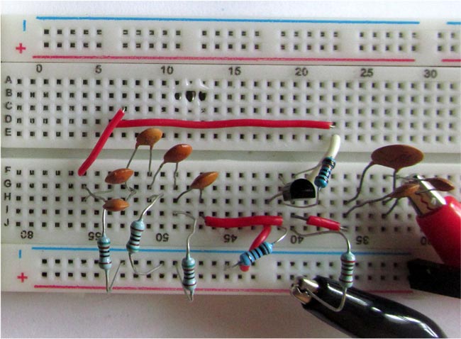
If you see the below picture of breadboard connections, you will find more capacitors than shown in the circuit diagram above. That’s because we have connected some capacitor in series and parallel to get the required values of capacitors shown in circuit diagram. You can also use any NPN-transistor instead of the above one in the circuit. Also you can change the value of resistor and capacitor to change the level of frequency.
Working of Sine Wave Generator Circuit:
Here we are giving 12v to the circuit and we cannot feed it directly to the transistor. So, for this we are using resistor R1 and R2, making a voltage divider circuit for biasing transistor Q1. We have used a NPN type transistor which conducts the current or get forward biased only when a positive signal is provided to its base pin, otherwise, it remains open or reverse biased.
The pair of three resistor (R3, R5, and R6) and capacitor (C1, C2, and C3) makes an RC oscillator circuit. It’s a type of feedback oscillator which consists of an amplifying device like transistor as used in our circuit or we can also use an op-amp.
Initially, the input at RC circuit is DC but after the first switch it is converted into sine wave and then it remains in the sine wave.
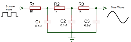
We have used three capacitors, each capacitor will give 60 degree of phase shift. So, the total phase shift we get is 180 degree which a sine wave requires.
In the RC Oscillator, some of the output energy is fed back to its input, for getting positive feedback, positive feedback helps the amplitude of the output to remain stable. Hence, the output of the RC circuit is sine wave with 180 degree of phase shift, which is fed to the transistor and here the transistor is working as an amplifier which amplifies the sine wave and we received it at output pin.
The capacitor C5 acts as coupling capacitor which blocks the DC and allows only sine wave to pass through it and resistor R4 is to limit the collector current.
Sine Wave Generator using 4047 IC
We can also use IC 4047 to generate sine wave. This IC is generally used in Inverter circuit and we have previously made a Square wave generator using this IC, by adding few resistors and capacitors in previous circuit, we can obtain sine wave with IC 4047, as shown in the circuit diagram below:


Below is that little circuit we need to add in our Square wave generator to convert the square wave into a sinusoidal wave.
Comments
Please what's the terminal
Please what's the terminal for input and output. And how do I increase the frequency to 50hz and also I want to use as inverter how do I increase the power rating. Thanks

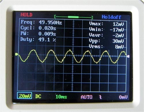
I spent a whole working day trying to get a 50Hz Sine Wave for PWM, with LM339 in Bubba Oscillator and RC Oscillator...but nothing achieved. Your circuit worked great, I have done little modifications but got 50Hz bang on!!! Thanks Bro...You're a life saver :)