

Sometimes, we might need an AC bulb flasher circuit that can blink a series of bulbs in a particular time interval for decorative purposes. By controlling the flashing time interval and sequence, we can make a series of bulbs look beautiful for outdoor decoration in Cafeteria, Restaurants, etc. or even used it for heavy Christmas light decoration, so here I have shared a simple and low-cost effective solution, which can also be built under a dollar. We just need a couple of very commonly available components for making this project. The circuit of this project consists of a potentiometer through which you can control the flashing speed of the AC bulb or LED chain lights. You can also check out the AC dimmer circuit, which combined with this circuit can not only flash the AC bulbs but can also control its intensity.
Note: Working with AC voltage can become seriously dangerous. Do not attempt this circuit if you do not have prior experience working with AC mains. You have been warned.
Components Required
| Sl. No | Component name | Value | Quantity |
| 1 | IC | LM555 | 1 |
| 2 | Optocoupler | Moc 3021 | 1 |
| 3 | Triac | Bt134 / bt 136 / bt139 | 1 |
| 4 | Resistance | 100 k | 2 |
| 5 | Resistance | 220 ohms | 2 |
| 6 | Resistance | 470 ohms | 1 |
| 7 | LED | 5mm | 1 |
| 8 | Ac bulb | 60w/100 w/ 200 w / 500w | 1 |
| 9 | Capacitor | 100 uf/ 25 v | 1 |
| 10 | Pot (VC) | 470k | 1 |
| 11 |
Some jumper wire, USB cable, mobile charger |
||
Circuit Diagram
The complete circuit diagram for the AC bulb blinking circuit can be found below. It is a simple circuit which consists of a 555 Timer IC to generate PWM pulse, this pulse is then used to control the blinking interval of the AC bulb through a TRIAC circuit which drives the AC bulb.

To help you with the connection, I have also provided a graphical representation of the same TRIAC Light Blink Circuit below.

Circuit Description
The circuit is very simple and easy. This is the application of the Astable multivibrator of NE555 Timer IC. According to the configuration of the NE555 timer IC, two external resistors and one capacitor (discharged) should be used. In the below part of the circuit, the resistance R1 (220 ohms) is connected from the IC discharged pin 7 to VCC positive 5V. Also, another resistance R5 (470K or 500 K) which we used as a variable resistance to control the output pulses, oscillator, and duty cycle & output frequency, connected from IC pin 7 to IC pin 2&6.
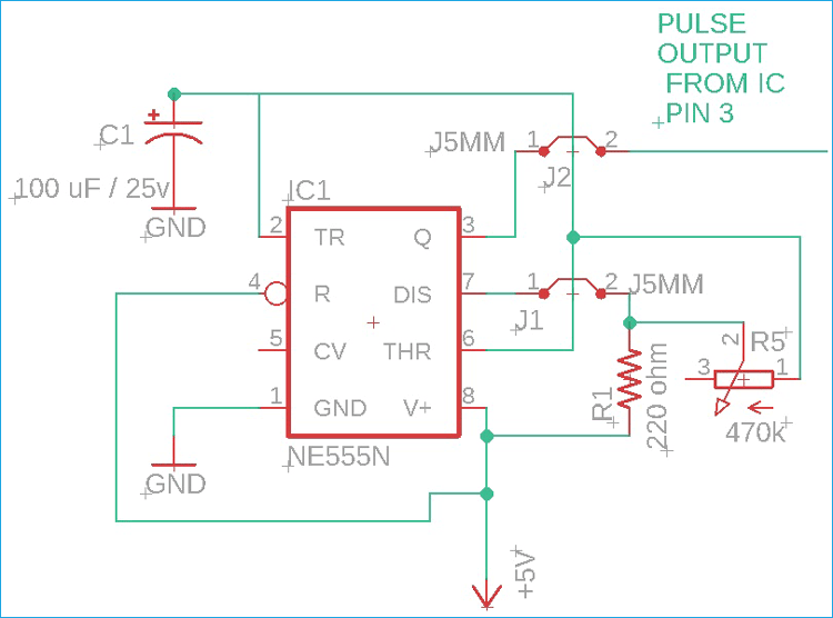
In this section of the circuit, we are getting Generated output pulse from the IC Output pin 3 which is applied to an L.E.D through a 220 ohms (R2) resistance, because of which the L.E.D gets on/off or High/Low according to the output pulse/frequency of the oscillations and the output pulse is also responsible for blinking or flashing of (dc side indicator) L.E.D and AC 220V bulb at the same time. This 220 ohms (R2) resistance is used just to resist the voltage for L.E.D or L.E.D protection purposes.
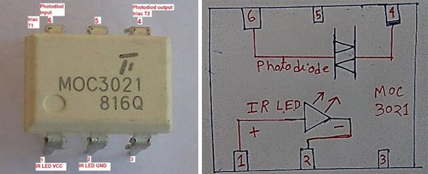
Also, the IC pulse output pin 3 is connected to MOC 3021 optocoupler VCC pin 1 through a 470 ohms (R3) resistance. This 470 ohms resistance is used for protection of optocoupler internal IR L.E.D, This MOC 3021 is a very advanced zero-crossing Triac driving Optocoupler which internally consists of an IR L.E.D and a photosensor or photoactive Triac, to understand the internal structure of optocoupler, you can follow my handmade diagram shown above.
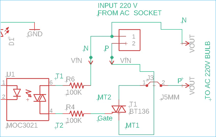
In the above section of the circuit, The T1 junction of the optocoupler (optocoupler pin 6) is connected with one of the AC terminals, which might be Neutral or Phase Line from the AC socket or outlets.
When the optocoupler internal IR L.E.D gets activated by receiving pulse voltage (through the resistance R3), internal IR LED radiates infrared which is sensed by the internal photosensitive Triac and allows conduction between T1 junction (optocoupler pin 6) and T2 junction (optocoupler pin 4).
From the optocoupler, T2 junction (optocoupler pin 4) voltage is applied to the Gate pin or middle pin of BT136 Triac through a 100 k resistance for Triac protection and the T1 terminal of BT136 connected with another AC terminal and we are taking the output from T2 terminal of the BT136 Triac for AC 220V Bulb or L.E.D chain Light.
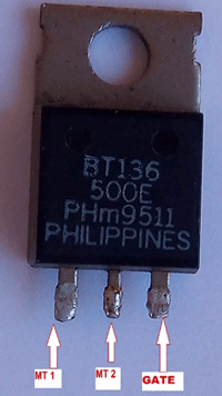
The Triac BT136 Capable of driving 4Amp of current, it means BT136 can handle up to 880 Watt of 220V AC Load.
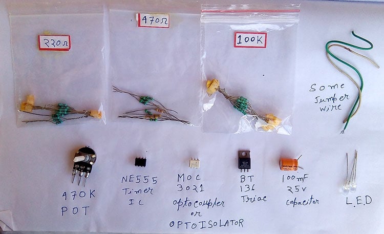
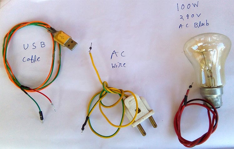
Collecting All the Components
All most of the components used in this project should be available easily in the local hardware shop. I have shown all the components that I have used below.
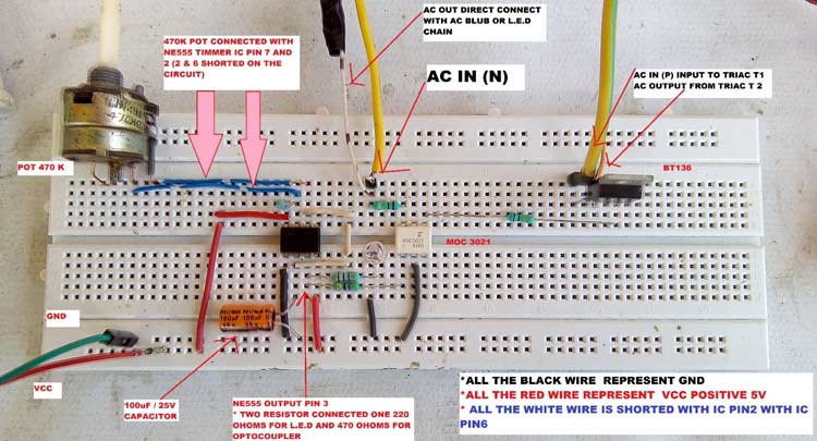
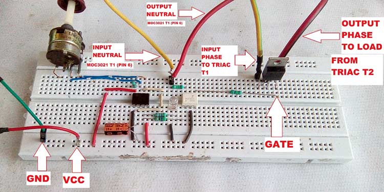
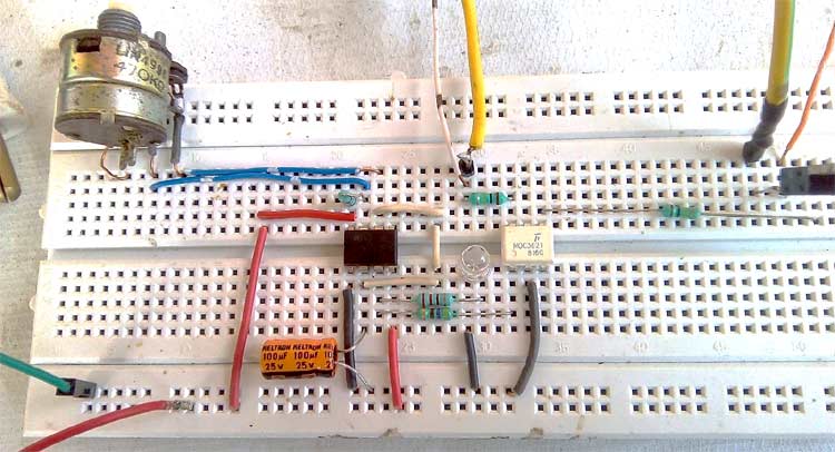
After collecting all the components and material, all the components are hooked up on my breadboard and the circuit looks like this.
Warning: Do not build AC circuits on a breadboard if you have an option. Try building it with a Perf Board. We have demonstrated with breadboard as temporary testing and demo.
The circuit should be easy to build, however, if you have some problem in getting it to work, check the following points.
- The variable resistance (R5) of 470k / 500 k / 330k / 1 Mega ohms can be used.
- For the pulse, indicator LED resistance R2 Value can be chosen from 220 ohms, 470 ohms, 330 ohms.
- For the MOC3021 internal IR L.E.D resistance, R3 value can be 470 Ohm or higher
- The AC load driving Triac can be chosen from BT136, BT139, BT134.
- Two 100K resistances, R6 and R4 are optional which are used for increased MOC3021 and BT136 Traic protection.
- Be careful during the operation of the circuit. Avoid touching optocoupler T1 or T2 or BT136 Triac terminal, otherwise, you may face an electric shock.
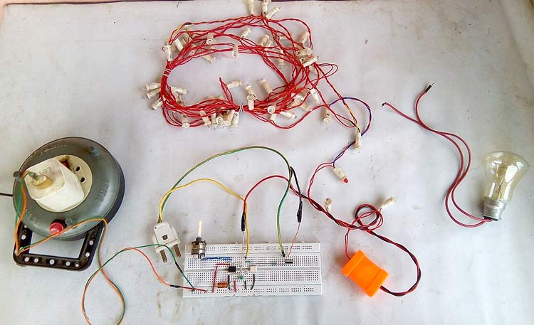
The 5V power for the circuit is taken from a 5v mobile charger which is connected to AC 220v outlet. An LED chain is connected as an output load with the circuit instead of a 100w bulb for testing purposes.
You can also check out the video below to see the entire working of this project where we demonstrate the circuit by controlling the flashing interval for both the AC bulb and the led chain. If you have any questions, you can leave that in the comment section below or write them on our forums.
Comments
Hi Robert. Did you ever get an answer to your question or get the circuit to work?
I am going to build this and see if it will work on 120 volt North American power. I may have to change the 100k series gate resistors to get enough gate current to trigger the triac.
Any thoughts?
Ken

This is a very interresting circuit and I've been looking for something like that for a while. Got all the components, followed the shcematic and built the breadboard for testing.
Unfortunately, it does not work. I can get the LED to blink at various rate using the variable resistance but the AC circuit refuses to work. I use 5vdc as input to the 555 timer (output is 2.9vdc into the optocoupler). since I am in Canada, it's 120VAC instead of 220 but I dont think it makes a difference. Also, I am using a LED house bulb instead of incandescent. Tried both to no avail. The TRIAC is a bt136 and tested OK.
Any Ideas....
Thanks
Robert