

Because of the COVID-19 virus, human lives and livelihoods change extensively and the only way to minimizing the spread of the virus is to maintain social distancing and follow guidelines proposed by our respective government. Not to mention sanitization and sterilization have become an indistinguishable part of our daily life. Talking about sanitization and sterilization, there is a problem, we can’t directly involve in the sterilization process, because there is a chance of getting the deadly virus from the contaminated space, but what we can do to solve this problem is to build a powerful, efficient, and autonomous robot, that can sterilize a place very easily without exposing ourselves. Robots are in use for several applications where humans can be at risk of exposure. So, in this tutorial will be building an ultraviolet sanitization robot that will be able to kill the coronavirus in the hospital and apartment building, and for that, we are going to be using an Arduino, some UV LEDs, and ultrasonic sensors.
In our previous article, we have made many bots like the Self Balancing Robot and the Obstacle Avoiding Robot, so do check those out if that sounds interesting to you.
Disclaimer: This is just a model project to understand the basics of a sanitization robot. We do not claim that the LEDs used in this project or the robot by itself can kill the CVOID-19 virus. This project is only for educational purposes.
How can UV Light Sterilize Viruses and Pathogens?
The primary function of the robot is to disinfect a room or a flat surface using ultraviolet germicidal irradiation. The robot has ultraviolet LEDs which is responsible for killing the virus. Bio-organisms such as bacteria, viruses are known to be deactivated when exposed to UV light. Ultraviolet light destroys the genetic material in pathogens—DNA in bacteria and RNA in viruses thus preventing them from reproducing. Virus-like COVID-19 can remain active on surfaces for a long time, and UV light has been proven to destroy the RNA in viruses, thus killing it in the process, which reduces the chance of transmission. If you are still curious to know how UV Lights can kill viruses, you can check out the linked article which explains in detail.
Working of the Ultraviolet Light Enabled Surface-Disinfecting Robot
This robot is completely automatic and it will detect obstacles and avoid those before a collision happen. there are many options to detect an obstacle, but for this project, we have chosen to do it with an ultrasonic sensor module because it has a lot more advantages over conventional IR based obstacle avoidance sensors, first is the range, it has a longer range compared to the range of an IR based proximity sensor. Second, like the IR sensor, sunlight doesn’t interfere with the sensing capabilities of the sensor. The image below shows all the sensors used in this project.
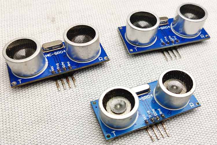
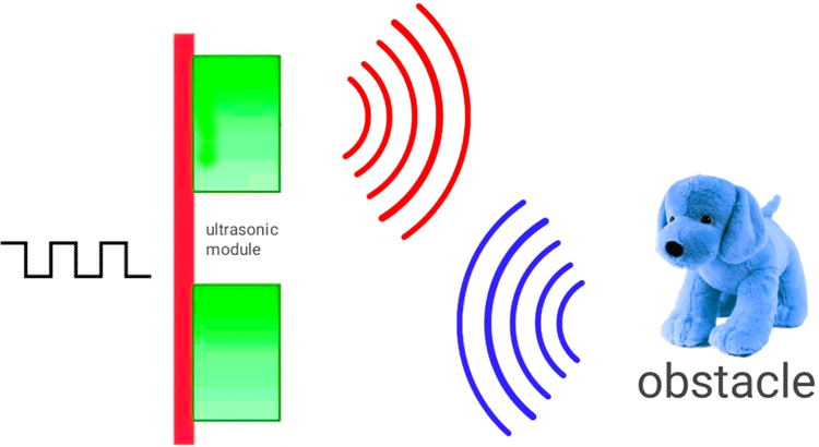
The HC-SR04 ultrasonic distance sensor module has 4 pins VCC, Trigger, Echo, and Ground. It has one ultrasonic transmitter and one receiver. The working is very simple, first module transmits ultrasonic wave which travels through air, hits an obstacle, and bounce back that is when the receiver receives that wave. To measure the distance of an object, we need to calculate the time taken to bounce back the wave. We can calculate this time with the help of a microcontroller and with the help of this equation Distance= speed of sound*time taken, we can calculate the distance of the obstacle.
If you did not hear about this sensor and want to learn more about it, do check out our take on Arduino Based Ultrasonic Distance Sensor project, there we have discussed the working principle of this sensor in detail.
In this robot, we have three ultrasonic sensors for detecting obstacles in the left, right, and front. When an obstacle comes in front of any sensor (at a certain distance) the robot will turn in to the opposite side and avoid that obstacle for example if an obstacle comes in front of the left sensor robot moves to the right.
While the robot is powered ON, the UV LEDs will stay ON and the sterilization process will continue. It has a total of ten UV LEDs (Two on each side and two on the downside) so this gives a 360°+ downside sterilization. This robot is 100% safe to operate and it will detect items in the environment for its operation and the safety of operators (obstacle avoidance). The robot is fully autonomous when UV irradiation is being performed this robot has a full 360-degree movement.
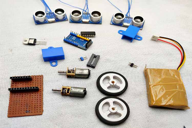
Components Needed to Build the Ultraviolet Light Enabled Surface-Disinfecting Robot
As we have used very generic components to build the control and hardware section of the robot, you should be able to find all of those in your local hobby store. which is why a complete list of required material with an image is shown below.
- Arduino Pro Mini (1)
- HC-SR04 Ultrasonic module (3)
- L293D Motor driver (1)
- 5Volt N20 motors and mounting brackets (2)
- N20 motor wheels (2)
- UV LEDs (8)
- 7805 Voltage Regulator (1)
- 7.4V Li-Ion Battery (1)
- 330R Resistor (10)
- Dotted Board (1)
- Foam Board or MDF (As per Requirement)
- castor wheel (1)
Circuit Diagram - Ultraviolet Light Enabled Surface-Disinfecting Robot

It looks complicated at first, but it's very simple. We have three ultrasonic sensors that detect the obstacles. As we are using three ultrasonic sensors, we connect all respective Ground and VCC pins, the Ground pin goes to the ground of the Arduino, the VCC pin goes to the VCC pin of the Arduino. Connect trigger and echo pins to Arduino PWM pins, as shown in the circuit diagram. We are using the popular L293D motor driver IC to drive the motors, connect the two enable pins of the motor driver to 5v, also we need to connect the driver voltage pin to 5V because we are using 5V compatible motors. We have connected all the UV LEDs in parallel each of which contains a current limiting resistor and we tied them all up to VCC and ground. In our case, we choose this resistor according to the LED type we are using, the LEDs are generic type so I am using a 330ohm resistor. The Arduino, Ultrasonic modules, motor driver, and motors work on 5 Volt higher voltage will kill it and we are using a 7.4-volt battery to convert that into 5 Volt, 7805 voltage regulator is used.
Building the Circuit For the Robot using Arduino Pro Mini and A Piece of Dotted Board
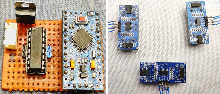
We are building a moving robot so we need to make everything as tiny as possible. To solder every component together, first, I took a very small dot PCB and place every component according to the circuit diagram, and solder everything. This part is very simple but do it with care. Also, try to use a female header pin for connecting Arduino pro mini and motors. After completing the soldering process, the board and the sensors look like the image shown below.

Building the Enclosure for Arduino Based Sterilizing Robot
We need to place the three ultrasonic sensor modules and hide all other circuitry for better finishing, that is why we need an enclosure. For our build, we decided to build it ourselves, while building, we have plenty of options, like foam sheet, MDF, cardboard, etc. Here we choose to go for a foam sheet because it's very easy to modify and the finishing looks great. If you have anything else in your mind, you can go for that.
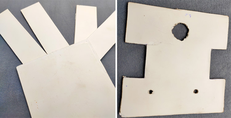
To build the enclose, first we took the form sheet and drawn all the necessary blocks, after which we cut them together for later use. The first four blocks we cut was 11 CM’s each, once that was done, we cut out the bottom of the bot using four, 3CM square blocks and we drilled all the necessary holes, the first big hole will be used for the castor wheel and the other two will hold the UV LEDs. You can check out the image for a better understanding.
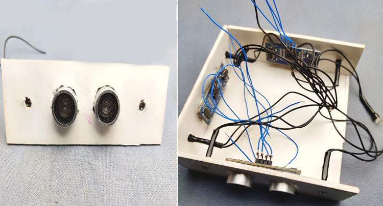
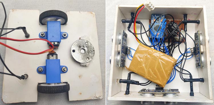
After cutting and drilling all the pieces, we mounted all the N20 motors on chase using its brackets. On the other square, we fixed four rectangles like a box and insert ultrasonic sensors and LEDs. After checking everything once again, we finally place the battery and close it with motor chases. But before closing, we put a switch outside. That's all about building the robot if you are confused with anything, you can refer to the images.
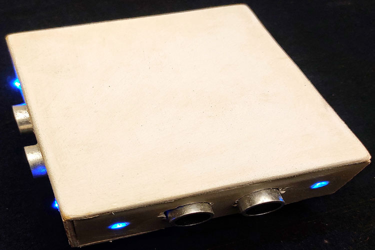
As you can see, the image below shows the final build and it looks and works great, you can find a video that shows the working of this robot.
Code Explanation - Ultraviolet Light Enabled Surface-Disinfecting Robot
Below we have described the code in a step-by-step manner. We are not using any extra libraries, to decode the distance data from the HC-SR04 sensor, because it's very simple. In the following, we described how first we need to define the Trigger Pin and Echo Pin which are connected to the Arduino board. In this project, we have three Echo Pins and three trigger pins. Note that 1 means left sensor, 2 is the front sensor, and 3 is the right sensor.
const  int trigPin1 = 3;
const int echoPin1 = 5;
const int trigPin2 = 6;
const int echoPin2 =9;
const int trigPin3 = 10;
const int echoPin3 = 11;
Then we defined variables for the distance which all are (int) type variables and for the duration, we chose to use (long). Again we have three of each.
long duration1;
 long duration2;
 long duration3;
int distanceleft;
int distancefront;
int distanceright;
Next, in the setup section, we need to make all the perspective pins as input or output using the pinModes() function. To send ultrasonic waves from the module, we need to enable trigger pin to high that is all trigger pins should define as OUTPUT. And to receive the echo, we need to read the state of echo pins so all echo pins should define as INPUT. Also, we enable the serial monitor for troubleshooting
pinMode(trigPin1, OUTPUT);
pinMode(trigPin2, OUTPUT);
pinMode(trigPin3, OUTPUT);
pinMode(echoPin1, INPUT);
pinMode(echoPin2, INPUT);
pinMode(echoPin3, INPUT);
Serial.begin(9600);
And these digital pins are defined as OUTPUT for the input of the motor driver.
pinMode(4, OUTPUT);
pinMode(7, OUTPUT);
pinMode(8, OUTPUT);
pinMode(12, OUTPUT);
In the main loop, we have three sections for three sensors. All the sections work the same but each for different sensors. In this section, we read the obstacle distance from each sensor and store it in each defined integer. To read the distance, first, we have to make sure that the trigger pins are clear, for that, we need to set the trigger pin to LOW for 2 µs. Now, for generating the ultrasonic wave, we need to turn the trigger pin HIGH for 10 µs. This will send the ultrasonic sound. And with the help of the pulseIn() function, we can read the travel time, and we store that value into the variable “duration”. This function has 2 parameters, the first one is the name of the echo pin and for the second one, you can write either HIGH or LOW. HIGH means that the pulseIn() function will wait for the pin to go HIGH caused by the bounced sound wave and it will start counting, then it will wait for the pin to go LOW when the sound wave will end which will stop the counting. And this function gives the length of the pulse in microseconds. For calculating the distance, we will multiply the duration by 0.034 (speed of sound in air is 340m/s ) and divide it by 2 (this is due to the back and forth traveling of the sound wave). Finally, we store the distance of each sensor in corresponding integers.
digitalWrite(trigPin1, LOW);
delayMicroseconds(2);
digitalWrite(trigPin1, HIGH);
delayMicroseconds(10);
digitalWrite(trigPin1, LOW);
duration1 = pulseIn(echoPin1, HIGH);
distanceleft = duration1 * 0.034 / 2;
Serial.print("Distance1: ");
Serial.println(distanceleft);
After getting distance from each sensor, we can control the motors with the help of an if statement, thus we control the movement of the robot. This is very simple, first, we gave an obstacle distance value in this case that is 15cm (change this value as your wish). Then we gave conditions according to that value. For example, when an obstacle comes in front of the left sensor (that is the distance of the left sensor should below or equals to 15 cm ) and the other two distances are high (that means no obstacle is in front of that's sensors), then with the help of digital write function, we can drive the motors to right.
if ((distanceleft <= 15 && distancefront <= 15 && distanceright > 15) || (distanceleft <= 15 && distancefront > 15 && distanceright > 15))
The above condition simply means if any obstacle comes in front of the right sensor (the distance of right sensor is less than 15 cm) and also in the front sensor AND if there are no obstacles present in front of the left sensors OR if an obstacle presents only in front of the left sensor.
Below we have separately explained the code used to move the motor Left, Right, and Forward.
This Section of the Code is Used to Move the Robot Right:
 digitalWrite(4, HIGH);
 digitalWrite(7, LOW);
 digitalWrite(8, HIGH);
 digitalWrite(12, LOW);
Similarly, I gave conditions for the right movement and straight movement.
This Section of the Code is Used to Move the Robot Left:
 if ((distanceleft > 15 && distancefront <= 15 && distanceright <= 15) || (distanceleft > 15 && distancefront > 15 && distanceright <= 15) ||  (distanceleft > 15 && distancefront <= 15 && distanceright > 15) )
 digitalWrite(4, LOW);
digitalWrite(7, HIGH);
digitalWrite(8, HIGH);
digitalWrite(12, LOW);
This Section of the Code is Used to Move the Robot Straight:
 if ((distanceleft <= 15 && distancefront > 15 && distanceright <= 15) || (distanceleft > 15 && distancefront > 15 && distanceright > 15))
  {
    digitalWrite(4, HIGH);
    digitalWrite(7, LOW);
    digitalWrite(8, HIGH);
    digitalWrite(12, LOW);
   }
That's it for this build. The complete working of the project can be found in the video linked at the bottom of this page. If you have any questions, comment on it.
Complete Project Code
// defining the pins
const int trigPin1 = 3;
const int echoPin1 = 5;
const int trigPin2 = 6;
const int echoPin2 = 9;
const int trigPin3 = 10;
const int echoPin3 = 11;
// defining variables
long duration1;
long duration2;
long duration3;
int distanceleft;
int distancefront;
int distanceright;
void setup() {
  pinMode(trigPin1, OUTPUT);
  pinMode(trigPin2, OUTPUT);
  pinMode(trigPin3, OUTPUT);// Sets the trigPin as an Output
  pinMode(echoPin1, INPUT); // Sets the echoPin as an Input
  pinMode(echoPin2, INPUT);
  pinMode(echoPin3, INPUT);
  Serial.begin(9600); // Starts the serial communication
  pinMode(4, OUTPUT);
  pinMode(7, OUTPUT);
  pinMode(8, OUTPUT);
  pinMode(12, OUTPUT);
}
void loop() {
  digitalWrite(trigPin1, LOW);
  delayMicroseconds(2);
  digitalWrite(trigPin1, HIGH);
  delayMicroseconds(10);
  digitalWrite(trigPin1, LOW);
  duration1 = pulseIn(echoPin1, HIGH);
  distanceleft = duration1 * 0.034 / 2;
  Serial.print("Distance1: ");
  Serial.println(distanceleft);
  digitalWrite(trigPin2, LOW);
  delayMicroseconds(2);
  digitalWrite(trigPin2, HIGH);
  delayMicroseconds(10);
  digitalWrite(trigPin2, LOW);
  duration2 = pulseIn(echoPin2, HIGH);
  distancefront = duration2 * 0.034 / 2;
  Serial.print("Distance2: ");
  Serial.println(distancefront);
  digitalWrite(trigPin3, LOW);
  delayMicroseconds(2);
  digitalWrite(trigPin3, HIGH);
  delayMicroseconds(10);
  digitalWrite(trigPin3, LOW);
  duration3 = pulseIn(echoPin3, HIGH);
  distanceright = duration3 * 0.034 / 2;
  Serial.print("Distance3: ");
  Serial.println(distanceright);
  if ((distanceleft <= 15 && distancefront > 15 && distanceright <= 15) || (distanceleft > 15 && distancefront > 15 && distanceright > 15))
  {
    digitalWrite(4, HIGH);
    digitalWrite(7, LOW);
    digitalWrite(8, HIGH);
    digitalWrite(12, LOW);
  }
  if ((distanceleft <= 15 && distancefront <= 15 && distanceright > 15) || (distanceleft <= 15 && distancefront > 15 && distanceright > 15))
  {
    digitalWrite(4, HIGH);
    digitalWrite(7, LOW);
    digitalWrite(8, LOW);
    digitalWrite(12, HIGH);
  }
  if ((distanceleft > 15 && distancefront <= 15 && distanceright <= 15) || (distanceleft > 15 && distancefront > 15 && distanceright <= 15) ||  (distanceleft > 15 && distancefront <= 15 && distanceright > 15) )
  {
    digitalWrite(4, LOW);
    digitalWrite(7, HIGH);
    digitalWrite(8, HIGH);
    digitalWrite(12, LOW);
  }
}Comments
how do we design pcb for this.
Can i use Arduino uno instead of pro mini
Is there any changes in programming?
battery mah?
hello, i tried the code in Arduino app , but it is not running properly. Can you please help me in it.

can u let me known if there are different program for different sensors used in the project