

Keypads are widely used input devices being used in various electronics and embedded projects. They are used to take inputs in the form of numbers and alphabets, and feed the same into system for further processing. In this tutorial we are going to interface a 4x4 matrix keypad with PIC16F877A.
Before going into the detail logic and learn how to use the keypad, we will need to know few things.
Why we need 4x4 Keypad:
Typically we use single I/O pin of a microcontroller unit to read the digital signal, like a switch input. In few applications where 9, 12, 16 keys are needed for input purposes, if we add each key in a microcontroller port, we will end up using 16 I/O ports. This 16 I/O ports are not only for reading I/O signals, but they can be used as peripheral connections too, like ADC supports, I2C, SPI connections are also supported by those I/O pins. As those pins are connected with the switches/keys, we can’t use them but only as I/O ports. This is makes no sense at all. So, how to reduce pin count? The answer is, using a hex keypad or matrix keypad; we can reduce pin counts, which associate 4x4 matrix keys. It will use 8 pins out of which 4 connected in rows and 4 connected in columns, therefore saving 8 pins of the microcontroller’s.
How 4x4 Matrix Keypad works:
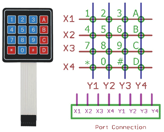
In the upper image a matrix keypad module is shown at the left. On the right the internal connection is shown as well as port connection. If we see the port there are 8 pins, first 4 from left to right are X1, X2, X3, and X4 are the rows, and last 4 from left to right are Y1, Y2, Y3, Y4 are four columns. If we make 4 rows or X side as output and make them logic low or 0, and make the 4 columns as input and read the keys we will read the switch press when correspondent Y gets 0.
Same thing will happen in n x n matrix where n is the number. That can be 3x3, 6x6 etc.
Now just think that 1 is pressed. Then the 1 is situated at X1 row and Y1 column. If X1 is 0, then the Y1 will be 0. By the same way we can sense each key in the X1 row, by sensing column Y1, Y2, Y3 and Y4. This thing happens for every switch and we will read the position of the switches in the matrix.
Each green circles is the switch and they both are connected together in the same way.
In this tutorial we will interface the key board with following specifications-
- We will use internal pull up
- We will add key de-bounce option
But when the switches are not pressed we need to make the Y1, Y2, Y3 and Y4 as high or 1. Otherwise we can’t detect the logic changes when the switch is being pressed. But we couldn’t make it by codes or program due to those pins are used as input, not output. So, we will use an internal operation register in the microcontroller and operate those pins as weak pull up enabled mode. By using this, there will be a logic high enable mode when it is in the default state.
Also, when we press key there are spikes or noise are generated with switch contacts, and due to this multiple switch press happens which is not expected. So, we will first detect the switch press, wait for few milliseconds, again check whether the switch is still pressed or not and if the switch is still pressed we will accept the switch press finally otherwise not. This is called as de-bouncing of the switches.
We will implement this all in our code, and make the connection on breadboard.
Also check how to interface 4x4 keypad with other Microcontrollers:
- Keypad Interfacing with Arduino Uno
- 4x4 Matrix Keypad Interfacing with 8051 Microcontroller
- 4x4 Keypad Interfacing with ATmega32 Microcontroller
- Raspberry Pi Digital Code Lock on Breadboard
Material Required:
- Breadboard
- Pic-kit 3 and development environment in your PC, i.e MPLABX
- Wires and connectors
- Character LCD 16x2
- 20Mhz Crystal
- 2 pcs 33pF ceramic disc cap.
- 4.7k resistor
- 10k preset (variable resistor)
- 4x4 Matrix keypad
- A 5 V adapter
Circuit Diagram:

We will connect the crystals and the resistor in the associated pins. Also, we will connect the LCD in 4 bit mode across PORTD. We connected the hex keypad or matrix keypad across the port RB4.
If you are new to PIC then start with Getting started with PIC Microcontroller: Introduction to PIC and MPLABX
Programming Explanation:
Complete code for interfacing Matrix Keypad with PIC Microcontroller is given at the end. Code is easy and self-explanatory. Keypad library is only thing to be understood in the code. Here we have used keypad.h and lcd.h Library to interface the keypad and 16x2 LCD. So lets see what is happening inside that.
Inside the keypad.h we will see that we have used xc.h header which is default register library, the crystal frequency is defined for the use for the use of delay used in kepad.c file. We defined the keypad ports at PORTRB register and defined individual pins as row (X) and columns (Y).
We also used two functions one for the keypad initialization which will redirect the port as output and input, and a switch press scan which will return the switch press status when called.
#include <xc.h>

#define _XTAL_FREQ 200000000 //Crystal Frequency, used in delay
#define X_1    RB0
#define X_2    RB1
#define X_3    RB2
#define X_4    RB3
#define Y_1    RB4
#define Y_2    RB5
#define Y_3    RB6
#define Y_4    RB7
#define Keypad_PORT          PORTB
#define Keypad_PORT_Direction     TRISB

void InitKeypad(void);
char switch_press_scan(void);
In the keypad.c we will see that below function will return the key press when the keypad scanner function not return ‘n’.
char switch_press_scan(void)                       // Get key from user
{
            char key = 'n';              // Assume no key pressed
            while(key=='n')              // Wait untill a key is pressed
            key = keypad_scanner();   // Scan the keys again and again
            return key;                  //when key pressed then return its value
}
Below is the keypad reading function. In each step we will make the row X1, X2, X3, and X4 as 0 and reading the Y1, Y2, Y3 and Y4 status. The delay is used for the debounce effect, when the switch is still pressed we will return the value associated with it. When no switch are pressed we will return ‘n ‘.
char keypad_scanner(void)
{
            X_1 = 0; X_2 = 1; X_3 = 1; X_4 = 1;
            if (Y_1 == 0) { __delay_ms(100); while (Y_1==0); return '1'; }
            if (Y_2 == 0) { __delay_ms(100); while (Y_2==0); return '2'; }
            if (Y_3 == 0) { __delay_ms(100); while (Y_3==0); return '3'; }
            if (Y_4 == 0) { __delay_ms(100); while (Y_4==0); return 'A'; }

            X_1 = 1; X_2 = 0; X_3 = 1; X_4 = 1;
            if (Y_1 == 0) { __delay_ms(100); while (Y_1==0); return '4'; }
            if (Y_2 == 0) { __delay_ms(100); while (Y_2==0); return '5'; }
            if (Y_3 == 0) { __delay_ms(100); while (Y_3==0); return '6'; }
            if (Y_4 == 0) { __delay_ms(100); while (Y_4==0); return 'B'; }

            X_1 = 1; X_2 = 1; X_3 = 0; X_4 = 1;
            if (Y_1 == 0) { __delay_ms(100); while (Y_1==0); return '7'; }
            if (Y_2 == 0) { __delay_ms(100); while (Y_2==0); return '8'; }
            if (Y_3 == 0) { __delay_ms(100); while (Y_3==0); return '9'; }
            if (Y_4 == 0) { __delay_ms(100); while (Y_4==0); return 'C'; }

            X_1 = 1; X_2 = 1; X_3 = 1; X_4 = 0;
            if (Y_1 == 0) { __delay_ms(100); while (Y_1==0); return '*'; }
            if (Y_2 == 0) { __delay_ms(100); while (Y_2==0); return '0'; }
            if (Y_3 == 0) { __delay_ms(100); while (Y_3==0); return '#'; }
            if (Y_4 == 0) { __delay_ms(100); while (Y_4==0); return 'D'; }

    return 'n';
}
We will also set the weak pull up on the last four bits, and also set the direction of the ports as last 4 input and first 4 as output. The OPTION_REG &= 0x7F; is used to set the weak pull up mode on the last pins.
void InitKeypad(void)
{
            Keypad_PORT                = 0x00;        // Set Keypad port pin values zero
            Keypad_PORT_Direction = 0xF0;      // Last 4 pins input, First 4 pins output
            OPTION_REG &= 0x7F;
}
In the main PIC program (given below) we first set the configuration bits and included few needed libraries. Then in void system_init functions we initialize the keypad and LCD. And finally in in the main function we have read the keypad by calling the switch_press_scan() function and returning the value to lcd.
Download the complete code with header files from here and check the Demonstration video below.
Complete Project Code
/*

 * File:   main.c

 * Author: Sourav Gupta

 * By:- circuitdigest.com

 * Created on April 13, 2018, 2:26 PM

 */
// PIC16F877A Configuration Bit Settings
// 'C' source line config statements
// CONFIG

#pragma config FOSC = HS        // Oscillator Selection bits (HS oscillator)

#pragma config WDTE = OFF       // Watchdog Timer Enable bit (WDT disabled)

#pragma config PWRTE = OFF      // Power-up Timer Enable bit (PWRT disabled)

#pragma config BOREN = ON       // Brown-out Reset Enable bit (BOR enabled)

#pragma config LVP = OFF         // Low-Voltage (Single-Supply) In-Circuit Serial Programming Enable bit (RB3/PGM pin has PGM function; low-voltage programming enabled)

#pragma config CPD = OFF        // Data EEPROM Memory Code Protection bit (Data EEPROM code protection off)

#pragma config WRT = OFF        // Flash Program Memory Write Enable bits (Write protection off; all program memory may be written to by EECON control)

#pragma config CP = OFF         // Flash Program Memory Code Protection bit (Code protection off)

#include <xc.h>

#include <stdio.h>

#include <string.h>

#include "supporing_cfile/lcd.h"

#include "supporing_cfile/Keypad.h"
/*

 Hardware related definition

 */

#define _XTAL_FREQ 200000000 //Crystal Frequency, used in delay
/*

 Other Specific definition

 */

void system_init(void);

void main(void){

    system_init();

    char Key = 'n';

    lcd_com(0x80);

    lcd_puts("CircuitDigest");

    lcd_com(0xC0);

    while(1){

        Key = switch_press_scan();

        lcd_data(Key);

    }
}
/*

 *  System Init

 */

void system_init(void){

    TRISD = 0x00;

    lcd_init(); // This will initialise the lcd

    InitKeypad();

}
Comments
What do you mean specifically
What do you mean specifically, the keypad has 8 pins and I am connecting them to PORTB on my PIC18F47K40
I am having trouble
I am having trouble displaying the values entered by the keypad. It seems like the keypad is not working.

i have used same code in pic16f887 controller but keypad is not work do you please tell the region behind that. for simulation i am using protious latest version