
Designers use many wireless communication systems like Bluetooth Low Energy (BLE 4.0), Zigbee, ESP8266 Wi-Fi Modules, 433MHz RF Modules, Lora, nRF etc. And the selection of medium depends on the type of application it is being used in. Among all, one popular wireless medium for local network communication is the nRF24L01. These modules operate on 2.4GHz (ISM band) with baud rate from 250Kbps to 2Mbps which is legal in many countries and can be used in industrial and medical applications. It is also claimed that with proper antennas these modules can transmit and receive signals upto a distance of 100 meters between them. We previously used nRF24L01 with Arduino to control servo motor and create a Chat Room.
Here we will use nRF24L01 – 2.4GHz RF Transceiver module with Arduino UNO and Raspberry Pi to establish a wireless communication between them. The Raspberry pi will act as a transmitter and Arduino Uno will listen to Raspberry Pi and print the message sent by Raspberry Pi using nRF24L01 on a 16x2 LCD. nRF24L01 also have inbuilt BLE capabilities and it can also communicate wirelessly using BLE.
The tutorial is divided into two sections. The first section will include the interfacing of nRF24L01 with Arduino to act as Receiver and the second section will include the interfacing of nRF24L01 with Raspberry Pi to act as Transmitter. The complete code for both of the section with working video will be attached at the end of this tutorial.
The nRF24L01 RF Module
The nRF24L01 modules are transceiver modules, meaning each module can both send and receive data but since they are half-duplex they can either send or receive data at a time. The module has the generic nRF24L01 IC from Nordic semi-conductors which is responsible for transmission and reception of data. The IC communicates using the SPI protocol and hence can be easily interfaced with any microcontrollers. It gets a lot easier with Arduino since the libraries are readily available. The pinouts of a standard nRF24L01 module is shown below
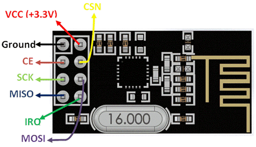
The module has on operating voltage from 1.9V to 3.6V (typically 3.3V) and consumes very less current of only 12mA during normal operation which makes it battery efficient and hence can even run on coin cells. Even though the operating voltage is 3.3V most of the pins are 5V tolerant and hence can be directly interfaced with 5V microcontrollers like Arduino. Another advantage of using these modules is that, each module has 6 Pipelines. Meaning, each module can communicate with 6 other modules to transmit or receive data. This makes the module suitable for creating star or mesh networks in IoT applications. Also they have a wide address range of 125 unique ID’s, hence in a closed area we can use 125 of these modules without interfering with each other.
Circuit Diagram
nRF24L01 with Arduino:
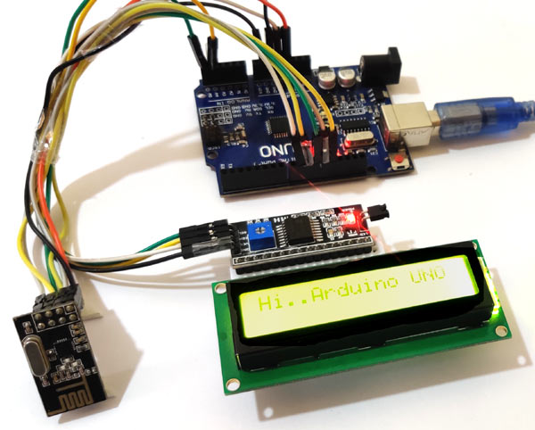
The circuit diagram for connecting nRF24L01 with Arduino is easy and doesn’t have much components. The nRF24l01 will be connected by SPI interface and the 16x2 LCD is interfaced with I2C protocol which uses only two wires.

nRF24L01 with Raspberry Pi:
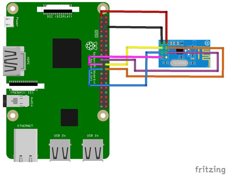
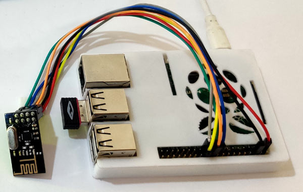
The circuit diagram for connecting nRF24L01 with Raspberry Pi is also very simple and only the SPI interface is used to connect Raspberry Pi and nRF24l01.
Programming Raspberry Pi to Send Message using nRF24l01
Programming of the Raspberry Pi will be done using Python3. You can also use C/C++ as Arduino. But there is already a library available for nRF24l01 in python which can be downloaded from github page. Note that the python program and the library should be on the same folder or the python program will not be able to find the library. After downloading the library just extract and make a folder where all programs and library files will be stores. When library installation is done, just start writing the program. The program start with the inclusion of libraries which will be used in code like import GPIO library for accessing the Raspberry Pi GPIOs and import time for accessing the time related functions. If you are new to Raspberry Pi then fall back to getting started with Raspberry pi.
import RPi.GPIO as GPIO
import time
import spidev
from lib_nrf24 import NRF24
Set the GPIO mode in "Broadcom SOC channel". This means that you are referring to the pins by the "Broadcom SOC channel" number, these are the numbers after "GPIO"( for e.g. GPIO01,GPIO02…). These are not the Board Numbers.
GPIO.setmode(GPIO.BCM)
Next we will set it up the pipe address. This address is important in order to communicate with the Arduino receiver. The address will be in the hex code.
pipes = [[0xE0, 0xE0, 0xF1, 0xF1, 0xE0], [0xF1, 0xF1, 0xF0, 0xF0, 0xE0]]
Begin the radio using GPIO08 as CE and GPIO25 as CSN pins.
radio.begin(0, 25)
Set payload size as 32 bit, channel address as 76, data rate of 1 mbps and power levels as minimum.
radio.setPayloadSize(32)
radio.setChannel(0x76)
radio.setDataRate(NRF24.BR_1MBPS)
radio.setPALevel(NRF24.PA_MIN)
Open the pipes to start writing the data and print the basic details of nRF24l01.
radio.openWritingPipe(pipes[0])
radio.printDetails()
Prepare a message in the string form. This message will be sent to Arduino UNO.
sendMessage = list("Hi..Arduino UNO")
while len(sendMessage) < 32:
    sendMessage.append(0)
Start writing to the radio and keep on writing the complete string till the radio is available. Along with it, note down the time and print a debug statement of message delivery.
while True:
    start = time.time()
    radio.write(sendMessage)
    print("Sent the message: {}".format(sendMessage))
send
    radio.startListening()
If the string is completed and pipe is closed then print a debug message of timed out.
while not radio.available(0):
        time.sleep(1/100)
        if time.time() - start > 2:
            print("Timed out.")  # print error message if radio disconnected or not functioning anymore
            break
Stop listening to the radio and close the communication and restart the communication after 3 seconds to send another message.
  radio.stopListening()     # close radio
    time.sleep(3)  # give delay of 3 seconds
The Raspberry program is simple to understand if you know the basics of python. Complete Python program is given at the end of tutorial.
Executing the Python Program in Raspberry Pi:
Executing the program is very easy after following the below steps:
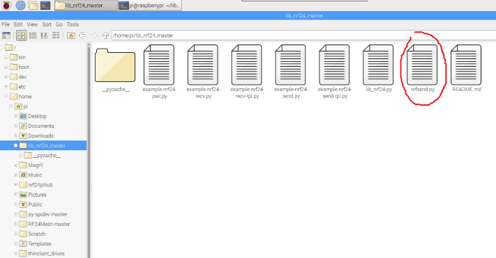
- Save the Python Program and Library files in the same folder.
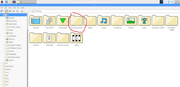
- My program file name for Sender is nrfsend.py and also every files are in the same folder
- Go to Command Terminal of Raspberry Pi. And locate the python program file by using “cd” command.
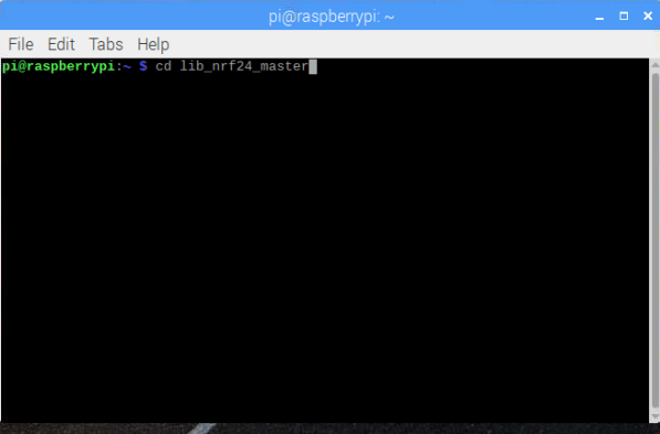
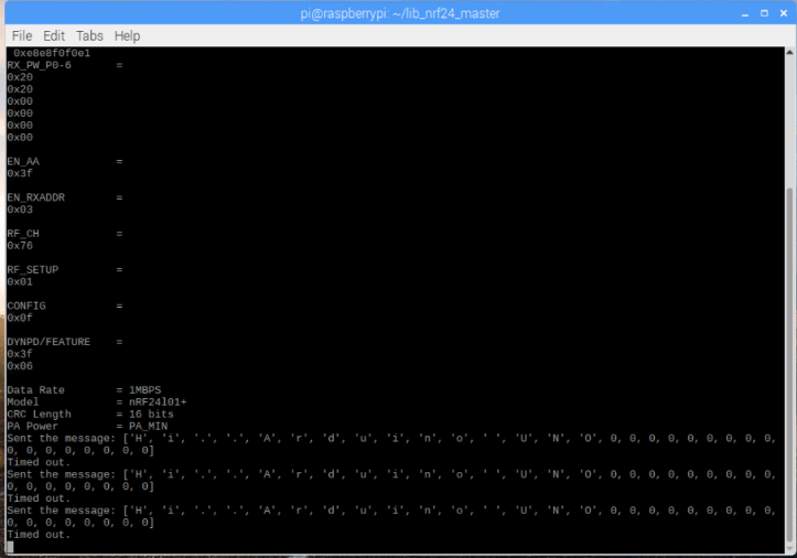
- Then open the folder and write command “sudo python3 your_program.py” and hit enter. You will be able to see the basic details of nRf24 and the radio will start sending the messages after every 3 seconds. The message debug will display after sending is done with all characters sent.
Now we will see the same program as receiver in the Arduino UNO.
Programming Arduino UNO to Receive Message using nRF24l01
Programming the Arduino UNO is similar to programming the Raspberry Pi. We will follow similar methods but with different programming language and steps. The steps will include the reading part of nRF24l01. The library for nRF24l01 for Arduino can be downloaded from github page. Start with including necessary libraries. We are using 16x2 LCD using I2C Shield so include Wire.h library and also the nRF24l01 is interfaced with SPI so include SPI library.
#include<SPI.h>
#include <Wire.h>
Include RF24 and LCD library for accessing the RF24 and LCD functions.
#include<RF24.h>
#include <LiquidCrystal_I2C.h>
The LCD address for I2C is 27 and it is a 16x2 LCD so write this into the function.
LiquidCrystal_I2C lcd(0x27, 16, 2);
The RF24 is connected with standard SPI pins along with CE in pin 9 and CSN in pin 10.
RF24 radio(9, 10) ;
Start the radio, set the power level and set channel to 76. Also set the pipe address same as Raspberry Pi and open the pipe to read.
radio.begin();
  radio.setPALevel(RF24_PA_MAX) ;
  radio.setChannel(0x76) ;
  const uint64_t pipe = 0xE0E0F1F1E0LL ;
  radio.openReadingPipe(1, pipe) ;
Begin the I2C communication and initialise the LCD display.
Wire.begin();
  lcd.begin();
  lcd.home();
  lcd.print("Ready to Receive");
Start listening to the radio for incoming messages and set the message length as 32 bytes.
radio.startListening() ;
  char receivedMessage[32] = {0}
If radio is attached then start reading the message and save it. Print the message to serial monitor and also print to the display until the next message arrives. Stop the radio to listen and retry after some interval. Here it is 10 micro seconds.
if (radio.available()) {
    radio.read(receivedMessage, sizeof(receivedMessage));        Serial.println(receivedMessage) ;
    Serial.println("Turning off the radio.") ;
    radio.stopListening() ;
    String stringMessage(receivedMessage) ;
    lcd.clear();
    delay(1000);
    lcd.print(stringMessage);
  }
Upload the complete code given at the end to the Arduino UNO and wait for the message to be received.
This finishes the complete tutorial on sending a message using Raspberry Pi & nRf24l01 and receiving it using Arduino UNO & nRF24l01. The message will be printed to the 16x2 LCD. The pipe addresses are very important in both Arduino UNO and Raspberry Pi. If you face any difficulty while doing this project then please comment below or reach to out forum for more detailed discussion.
Also check the demonstration video below.
Complete Project Code
NRF Transmitter Side Code (Raspberry Pi):
import RPi.GPIO as GPIO  # import gpio
import time      #import time library
import spidev
from lib_nrf24 import NRF24   #import NRF24 library
GPIO.setmode(GPIO.BCM)       # set the gpio mode
  # set the pipe address. this address shoeld be entered on the receiver alo
pipes = [[0xE0, 0xE0, 0xF1, 0xF1, 0xE0], [0xF1, 0xF1, 0xF0, 0xF0, 0xE0]]
radio = NRF24(GPIO, spidev.SpiDev())   # use the gpio pins
radio.begin(0, 25)   # start the radio and set the ce,csn pin ce= GPIO08, csn= GPIO25
radio.setPayloadSize(32)  #set the payload size as 32 bytes
radio.setChannel(0x76) # set the channel as 76 hex
radio.setDataRate(NRF24.BR_1MBPS)    # set radio data rate
radio.setPALevel(NRF24.PA_MIN)  # set PA level
radio.setAutoAck(True)       # set acknowledgement as true
radio.enableDynamicPayloads()
radio.enableAckPayload()
radio.openWritingPipe(pipes[0])     # open the defined pipe for writing
radio.printDetails()      # print basic detals of radio
sendMessage = list("Hi..Arduino UNO")  #the message to be sent
while len(sendMessage) < 32:
    sendMessage.append(0)
while True:
    start = time.time()      #start the time for checking delivery time
    radio.write(sendMessage)   # just write the message to radio
    print("Sent the message: {}".format(sendMessage))  # print a message after succesfull send
    radio.startListening()        # Start listening the radio

    while not radio.available(0):
        time.sleep(1/100)
        if time.time() - start > 2:
            print("Timed out.")  # print errror message if radio disconnected or not functioning anymore
            break

    radio.stopListening()     # close radio
    time.sleep(3)  # give delay of 3 seconds
# >

NRF Receiver Side Code (Arduino):
#include<SPI.h>                   // spi library for connecting nrf
#include <Wire.h>                             // i2c libary fro 16x2 lcd display
#include<RF24.h>                  // nrf library
#include <LiquidCrystal_I2C.h>     // 16x2 lcd display library
LiquidCrystal_I2C lcd(0x27, 16, 2);         // i2c address is 0x27
RF24 radio(9, 10) ;  // ce, csn pins
void setup(void) {
  while (!Serial) ;
  Serial.begin(9600) ;     // start serial monitor baud rate
  Serial.println("Starting.. Setting Up.. Radio on..") ; // debug message
  radio.begin();        // start radio at ce csn pin 9 and 10
  radio.setPALevel(RF24_PA_MAX) ;   // set power level
  radio.setChannel(0x76) ;            // set chanel at 76
  const uint64_t pipe = 0xE0E0F1F1E0LL ;    // pipe address same as sender i.e. raspberry pi
  radio.openReadingPipe(1, pipe) ;        // start reading pipe
  radio.enableDynamicPayloads() ;
  radio.powerUp() ;
  Wire.begin();                 //start i2c address
  lcd.begin();                    // start lcd
  lcd.home();
  lcd.print("Ready to Receive");  // print starting message on lcd
  delay(2000);
  lcd.clear();
}
void loop(void) {
  radio.startListening() ;        // start listening forever
  char receivedMessage[32] = {0} ;   // set incmng message for 32 bytes
  if (radio.available()) {       // check if message is coming
    radio.read(receivedMessage, sizeof(receivedMessage));    // read the message and save
    Serial.println(receivedMessage) ;    // print message on serial monitor
    Serial.println("Turning off the radio.") ;   // print message on serial monitor
    radio.stopListening() ;   // stop listening radio
    String stringMessage(receivedMessage) ;     // change char to string
    lcd.clear();    // clear screen for new message
    delay(1000);    // delay of 1 second
    lcd.print(stringMessage);   // print received mesage
  }
  delay(10);
}
Comments
Testing NRF24l01
Is there any way using the NRF libraries to test whether a NRF24l01 board is functioning and/or wired up correctly? I have tried several different libraries on Raspberry Pi and Arduino. The closest I get is that when I execute a receiver script it repeatedly acts as if it is receiving garbage data. Amazingly the same happens when I unplug the NRF24l01 completely! It is very hard to debug when you can't tell if data being reported as received is not actually coming from the board. Is there any methods that give health data or report values from registers on the board (that would fail if the board were not connected at all)? Thanks in advance!
RPi doesn't transmit
I can't figure out what I did wrong. The RPi is not sending, because the Arduino does not see data coming in.
Raspberry Pi 3B+
I'm sure my wiring is correct. SPI is enabled on the RPi. I loaded a new, latest (Buster) Raspbian. I ported the RPi program to another Arduino with radio, this worked.
I missed something. Can anyone help?
Raspberry Pi3 to Arduino UNO RF communication NOT
I have triple checked wiring having setup coding as per this article - no dialog! Tried Arduino to Arduino and it works! So have to assume that the Raspi doesn't like the Arduino - Huh!
Anyway, replaced nRF hardware at Raspi end, still no dialog... Instictively not happy about the "pipes" statement and the following list of param's. Can't find a way to code replicate the pipe numbers )as called for to be the same on both systems, relevant to the Arduino. Thought I have it but certainly it could be where the problem lies. Any help in this area would be gratefully accepted.
hi,
hi,
I found two problems why it did not work.
I have an Rasperry pi 4 and by default SPI master driver is disabled by default on Raspberry Pi OS.
To enable:
ensure the line
dtparam=spi=onisn't commented out in/boot/config.txt, and reboot. If the SPI driver was loaded, you should see the device/dev/spidev0.0.
https://circuitdigest.com/microcontroller-projects/wireless-rf-communication-between-arduino-and-raspberry-pi-using-nrf24l01
and the second problem was that CRC length was disabled:
to enable:
The problem is that I use Python to access the bus and it is not evident how, when and where I should set the speed of the SPI bus.
EDIT: I found it: In lib_nrf24.py in function:
def begin(self, csn_pin ...afterself.spidev.openadd:
self.spidev.max_speed_hz = 4000000
(in my case 5 MHz did not work)

I want to reverse this process, which seems simple enough. But where I run into a problem is getting the data from the nrf24l01 to the MQTT server. How can I do this? Is there a solution? My setup is:
remote motion+nrf24l01 (transmit only) ---)))) >>> (((---local nrf24l01+RPiAP/wMQTT (receive only)