

Every Engineer who loves to tinker with electronics at some point of time would want to have their own lab set-up. A Multimeter, Clamp meter, Oscilloscope, LCR Meter, Function Generator, Dual mode power supply and an Auto transformer are the bare minimum equipments for a decent lab set-up. While all of these can be purchased, we can also easily built few on our own like the Function Generator and the Dual mode power supply.
In this article we will learn how quickly and easily we can build our own Function generator using Arduino. This function generator a.k.a waveform generator can produce square wave (5V/0V) with frequency ranging from 1Hz to 2MHz, the frequency of the wave can be controlled by a knob and the duty cycle is hardcoded to 50% but it is easy to change that in the program as well. Apart from that, the generator can also produce since wave with frequency control. Do note that this generator is not of industrial grade and cannot be used for serious testing. But other than that it will come in handy for all hobby projects and you need not wait in weeks for the shipment to arrive. Also what’s more fun than using a device, that we built on our own.
Materials Required
- Arduino Nano
- 16*2 Alphanumeric LCD display
- Rotary Encoder
- Resistor(5.6K,10K)
- Capacitor (0.1uF)
- Perf board, Bergstik
- Soldering Kit
Circuit Diagram
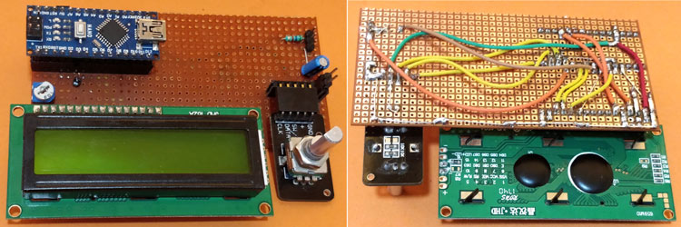
The complete circuit diagram this Arduino Function Generator is shown below. As you can see we have an Arduino Nano which acts as the brain of our project and an 16x2 LCD to display the value of frequency that is currently being generated. We also have a rotary encoder which will help us to set the frequency.

The complete set-up is powered by the USB port of the Arduino itself. The connections which I used previously didn’t turn out to work dues to some reasons which we will discuss later in this article. Hence I had to mess up with the wiring a bit by changing the pin order. Anyhow, you will not have any such issues as it is all sorted out, just follow the circuit carefully to know which pin is connect to what. You can also refer the below table to verify your connections.
| Arduino Pin | Connected to |
| D14 | Connected to RS of LCD |
| D15 | Connected to RN of LCD |
| D4 | Connected to D4 of LCD |
| D3 | Connected to D5 of LCD |
| D6 | Connected to D6 of LCD |
| D7 | Connected to D7 of LCD |
| D10 | Connect to Rotary Encoder 2 |
| D11 | Connect to Rotary Encoder 3 |
| D12 | Connect to Rotary Encoder 4 |
| D9 | Outputs square wave |
| D2 | Connect to D9 of Arduino |
| D5 | Outputs SPWM then converted to sine |
The circuit is pretty simple; we produce a square wave on pin D9 which can be used as such, the frequency of this square wave is controlled by the rotary encoder. Then to get a sine wave we produce SPWM signal on pin D5, the frequency of this has to be related with PWM frequency so we provide this PWM signal to pin D2 to act as an interrupt and then use the ISR to control the frequency of the since wave.
You can build the circuit on a breadboard or even get a PCB for it. But I decided to solder it on a Perf board to get the work done fast and make it reliable for long term use. My board looks like this once all the connections are complete.
If you want to know more on how the PWM and Sine wave is produced with Arduino read the following paragraphs, else you can scroll down directly to the Programming Arduino section.
Producing Square Wave with Variable Frequency
People who are using Arduino might be familiar that Arduino can produce PWM signals simply by using the analog write function. But this function is limited only to control the duty cycle of the PWM signal and not the frequency of the signal. But for a waveform generator we need a PWM signal whose frequency can be controlled. This can be done by directly controlling the Timers of the Arduino and toggling a GPIO pin based on it. But there are some pre-built libraries which do just the same and can be used as such. The library that we are using is the Arduino PWM Frequency Library. We will discuss more about this library in the coding section.
There are some drawbacks with this library as well, because the library alters the default Timer 1 and Timer 2 settings in Arduino. Hence you will no longer be able to use servo library or any other timer related library with your Arduino. Also the analog write function on pins 9,10,11 & 13 uses Timer 1 and Timer 2 hence you will not be able to produce SPWM on those pins.
The advantage of this library is that it does not disturb the Timer 0 of your Arduino, which is more vital than Timer 1 and Timer 2. Because of this you are free to use the delay function and millis() function without any problem. Also the pins 5 and 6 are controlled by Timer 0 hence we won’t be having problem in using analog write or servo control operation on those pins. Initially it took some time for me to figure this out and that is why the wiring is messed up a bit.
Here we have also built one Simple Square waveform generator, but to change the frequency of waveform you have to replace Resistor or capacitor, and it will hard to get the required frequency.
Producing Sine Wave using Arduino
As we know microcontrollers are Digital devices and they cannot produce Sine wave by mere coding. But there two popular ways of obtaining a sine wave from a microcontroller one is by utilizing a DAC and the other is by creating a SPWM. Unfortunately Arduino boards (except Due) does not come with a built-in DAC to produce sine wave, but you can always build your own DAC using the simple R2R method and then use it to produce a decent sine wave. But to reduce the hardware work I decided to use the later method of creating a SPWM signal and then converting it to Sine wave.
What is a SPWM signal?
The term SPWM stands for Sinusoidal Pulse Width Modulation. This signal is very much similar to the PWM, but for an SPWM signal the duty cycle is controlled in such a manner to obtain an average voltage similar to that of a sine wave. For example, with 100% duty cycle the average output voltage will be 5V and for 25% we will have 1.25V thus controlling the duty cycle we can get pre-defined variable average voltage which is nothing but a sine wave. This technique is commonly used in Inverters.
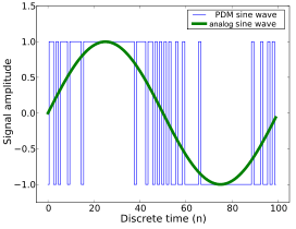
In the above image, the blue signal is the SPWM signal. Notice that the duty cycle of the wave is varied from 0% to 100% and then back to 0%. The graph is plotted for -1.0 to +1.0V but in our case, since we are using an Arduino the scale will be form 0V to 5V. We will learn how to produce SPWM with Arduino in the programming section below.
Converting SPWM to Sine wave
Converting a SPWM single to sine wave requires a H-bridge circuit which consists of minimum 4 power switches. We will not go much deeper into it since we are not using it here. These H-bridge circuits are commonly used in inverters. It utilizes two SPWM signals where one is phase shifted from the other and both the signals are applied to the power switches in the H-bridge to make diagonal opposing switches turn on and off and the same time. This way we can get a wave form that looks similar to sine wave but will practically not be closer to anything shown in the figure above (green wave). To get a pure since wave output we have to use a filter like the low-pass filter which comprises of an Inductor and Capacitor.
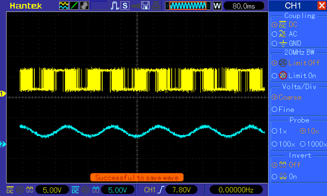
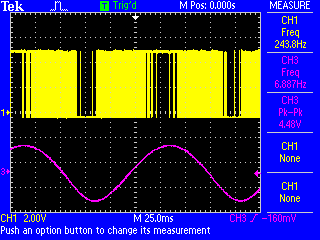
However in our circuit, we will not be using the sine wave to power anything. I simply wanted to create from the generated SPWM signal so I went with a simple RC-Filter. You can also try a LC-Filter for better results but I chose RC for simplicity. The value of my resistor is 620 Ohms and the capacitor is 10uF. The above image shows the SPWM signal (Yellow) from the pin 5 and the sine wave (Blue) which was obtained after passing it through a RC-Filter.
If you don’t want to vary the frequency, you can also generate sine wave by using this Simple Sine Wave Generator Circuit using Transistor.
Adding the Arduino PWM Frequency Library
The Arduino Frequency Library can be downloaded by clicking on the link below.
At the time of writing this article, the Arduino PWM Frequency Librarey V_05 is the latest one and it will get downloaded as a ZIP file. Extract the ZIP file ad you will get a folder called PWM. Then navigate to the Libraries folder of your Arduino IDE, for windows users it will be in your documents at this path C:\Users\User\Documents\Arduino\libraries. Paste the PWM folder into the libraries folder. Sometimes you might already have a PWM folder in there, in that case make sure you replace the old one with this new one.

Programming Arduino for Waveform Generator
As always the complete program for this project can be found at the bottom of this page. You can use the code as such, but make sure you have added the variable frequency library for Arduino IDE as discussed above else you will get compile time error. In this section let’s look in to the code to understand what is happening.
Basically we want to produce a PWM signal with variable frequency on pin 9. This frequency should be set using the rotary encoder and the value should also be displayed in the 16*2 LCD. Once the PWM signal is created on pin 9 it will create an interrupt on pin 2 since we have shorted both the pins. Using this interrupt we can control the frequency of the SPWM signal which is generated on pin 5.
As always we begin our program by including the required library. The liquid crystal library is in-built in Arduino and we just installed the PWM library.
#include <PWM.h> //PWM librarey for controlling freq. of PWM signal
#include <LiquidCrystal.h>
Next we declare the global variable and also mention the pin names for the LCD, Rotary Encoder and signal pins. You can leave this undisturbed if you have followed the circuit diagram above.
const int rs = 14, en = 15, d4 = 4, d5 = 3, d6 = 6, d7 = 7; //Mention the pin number for LCD connection
LiquidCrystal lcd(rs, en, d4, d5, d6, d7);

const int Encoder_OuputA  = 11;
const int Encoder_OuputB  = 12;
const int Encoder_Switch = 10;
const int signal_pin = 9;
const int Sine_pin = 5;
const int POT_pin = A2;

int Previous_Output;
int multiplier = 1;
double angle = 0;
double increment = 0.2;
int32_t frequency; //frequency to be set
int32_t lower_level_freq = 1; //Lowest possible freq value is 1Hz
int32_t upper_level_freq = 100000; //Maximum possible freq is 100KHz
Inside the setup function we initialize the LCD and serial communication for debugging purpose and then declare the pins of Encoder as input pins. We also display an intro message during the boot just to make sure things are working.
  lcd.begin(16, 2); //Initialise 16*2 LCD

  lcd.print("Signal Generator"); //Intro Message line 1
  lcd.setCursor(0, 1);
  lcd.print("-CircuitDigest "); //Intro Message line 2
  delay(2000);
  lcd.clear();
  lcd.print("Freq:00000Hz");
  lcd.setCursor(0, 1);
  lcd.print("Inc. by: 1 ");

Serial.begin(9600); //Serial for debugging

//pin Mode declaration
  pinMode (Encoder_OuputA, INPUT);
  pinMode (Encoder_OuputB, INPUT);
  pinMode (Encoder_Switch, INPUT);
Another important line is the InitTimerSafe which initializes the timer 1 and 2 for producing a variable frequency PWM. Once this function is called the default timer settings of Arduino will be altered.
InitTimersSafe(); //Initialize timers without disturbing timer 0
We also have the external interrupt running on pin 2. So whenever there a change in status of pin 2 an interrupt will be triggered which will run the Interrupt service routine (ISR) function. Here the name of the ISR function is generate_sine.
attachInterrupt(0,generate_sine,CHANGE);
Next, inside the void loop we have to check if the rotary encoder has been turned. Only if it has been turned we need to adjust the frequency of the PWM signal. We have already learnt how to interface Rotary Encoder with Arduino. If you are new here I would recommend you to fall back to that tutorial and then get back here.
If the rotary encoder is turned clockwise we increase the value of frequency by adding it with the value of multiplier. This way we can increase/decrease the value of frequency by 1, 10, 100 or even 1000. The value of multiplier can be set by pressing the rotary encoder. If the encoder is rotated we alter the value of frequency and produce a PWM signal on pin 9 with the following lines. Here the value 32768 sets the PWM to 50% cycle. The value 32768 is chosen, since 50% of 65536 is 32768 similarly you can determine the value for your required duty cycles. But here the duty cycle is fixed to 50%. Finally the function SetPinFrequencySafe is used to set the frequency of our signal pin that is pin 9.
pwmWriteHR(signal_pin, 32768); //Set duty cycle to 50% by default -> for 16-bit 65536/2 = 32768
SetPinFrequencySafe(signal_pin, frequency);
Inside the ISR function we write the code to generate SPWM signal. There are many ways to generate SPWM signals and even pre-built libraries are available for Arduino. I have used the simplest of all methods of utilizing the sin() function in Arduino. You can also try with the lookup table method if you are interested. The sin() returns a variable value (decimal) between -1 to +1 and this when plotted against time will give us a sine wave.
Now all we have to do is convert this value of -1 to +1 into 0 to 255 and feed it to our analog Write function. For which I have multiplied it with 255 just to ignore the decimal point and then used the map function to convert the value from -255 to +255 into 0 to +255. Finally this value is written to pin 5 using the analog write function. The value of angle is incremented by 0.2 every time the ISR is called this help us in controlling the frequency of the sine wave
   double sineValue = sin(angle);
   sineValue *= 255;
   int plot = map(sineValue, -255, +255, 0, 255);
   Serial.println(plot);
   analogWrite(Sine_pin,plot);
   angle += increment;
Testing the Arduino Function Generator on Hardware
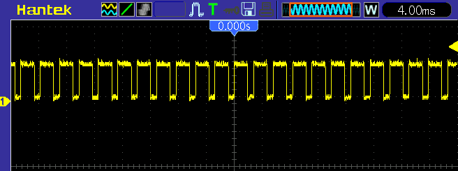
Build your hardware as per the circuit diagram and upload the code given at the bottom of this page. Now, you are all set to test your project. It would be a lot easier if you have a DSO (Oscilloscope) but you can also test it with an LED since the frequency range is very high.
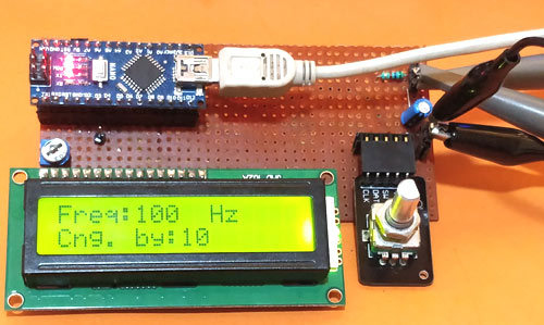
Connect the probe to the Square wave and sine wave pin of the circuit. Use two LEDs on these two pins if you do not have a scope. Power up the circuit and you should be greeted with the introductory message on the LCD. Then vary the Rotary encoder and set the required frequency you should be able to observe the square wave and sine wave on your scope as shown below. If you are using an LED you should notice the LED blinking at different intervals based on the frequency you have set.
The complete working of the waveform generator can also be found at the video given at the end of this page. Hope you enjoyed the project and learnt something useful from it. If you have any questions leave them in the comment section or you could also use the forums for other technical help.
Complete Project Code
#include <PWM.h> //PWM librarey for controlling freq. of PWM signal

#include <LiquidCrystal.h>
const int rs = 14, en = 15, d4 = 4, d5 = 3, d6 = 6, d7 = 7; //Mention the pin number for LCD connection

LiquidCrystal lcd(rs, en, d4, d5, d6, d7);
int Encoder_OuputA  = 11;

int Encoder_OuputB  = 12;

int Encoder_Switch = 10;

int Previous_Output;

int multiplier = 1;
double angle = 0;

double increment = 0.2;

const int signal_pin = 9;

const int Sine_pin = 5;

const int POT_pin = A2;

int32_t frequency; //frequency to be set

int32_t lower_level_freq = 1; //Lowest possible freq value is 1Hz

int32_t upper_level_freq = 100000; //Maximum possible freq is 100KHz
void setup()

{

  lcd.begin(16, 2); //Initialise 16*2 LCD
  lcd.print("Signal Generator"); //Intro Message line 1

  lcd.setCursor(0, 1);

  lcd.print("-CircuitDigest "); //Intro Message line 2

  delay(2000);

  lcd.clear();

  lcd.print("Freq:00000Hz");

  lcd.setCursor(0, 1);

  lcd.print("Inc. by: 1 ");


  Serial.begin(9600); //Serial for debugging

  InitTimersSafe(); //Initialize timers without disturbing timer 0


//pin Mode declaration

  pinMode (Encoder_OuputA, INPUT);

  pinMode (Encoder_OuputB, INPUT);

  pinMode (Encoder_Switch, INPUT);
  Previous_Output = digitalRead(Encoder_OuputA); //Read the inital value of Output A
 attachInterrupt(0,generate_sine,CHANGE);

}


void loop()

{

  if (digitalRead(Encoder_OuputA) != Previous_Output)

   {

     if (digitalRead(Encoder_OuputB) != Previous_Output)

     {

       frequency = frequency + multiplier;

      // Serial.println(frequency);

       pwmWriteHR(signal_pin, 32768); //Set duty cycle to 50% by default -> for 16-bit 65536/2 = 32768

       SetPinFrequencySafe(signal_pin, frequency);

       lcd.setCursor(0, 0);

       lcd.print("Freq:     Hz");

       lcd.setCursor(5, 0);

       lcd.print(frequency);

     }

     else

     {

       frequency = frequency -   multiplier;

      // Serial.println(frequency);

       pwmWriteHR(signal_pin, 32768); //Set duty cycle to 50% by default -> for 16-bit 65536/2 = 32768

       SetPinFrequencySafe(signal_pin, frequency);

       lcd.setCursor(0, 0);

       lcd.print("Freq:     Hz");

       lcd.setCursor(5, 0);

       lcd.print(frequency);

     }

   }
      if (digitalRead(Encoder_Switch) == 0)

   {

   multiplier = multiplier * 10;
   if (multiplier>1000)

   multiplier=1;


  // Serial.println(multiplier);

   lcd.setCursor(0, 1);

   lcd.print("Cng. by:     ");

   lcd.setCursor(8, 1);

   lcd.print(multiplier);


   delay(500);

   while(digitalRead(Encoder_Switch) == 0);

   }
   Previous_Output = digitalRead(Encoder_OuputA);


}
void generate_sine()

{

   double sineValue = sin(angle);

   sineValue *= 255;

   int plot = map(sineValue, -255, +255, 0, 255);

   Serial.println(plot);

   analogWrite(Sine_pin,plot);

   angle += increment;
   if (angle > 180)

   angle =0;

}
Comments
Well, bought a 'Genuine' Nano and tried this...
1. can't seem to run over 200HZ without hanging it.
Checked everything..Assuming D14 is A0 and D15 is A1, it's all wired correctly.
2. why is this line in there: const int POT_pin = A2; Doesn't seem like it's used anywhere. and no wires
are on A2.
I think it was touchy before because of the encoder.
Any ideas why yours does so much better than mine? My Nano is listed as "Arduino Nano [A000005] which should be v 3.x.
My encoder needed a pull-up on the switch. I had to swap the A and B signals from it as well.
The square wave output is not toggling until I turn the encoder backwards a step. Is this expected?
I am getting a sine wave out, but at a much lower frequency: setting at 1000Hz, I get a sinewave of 6.8Hz (after adding a 1uF cap). Is this expected?
Thanks!
David
Very nice design, very precisely wave. Is there any simple way to increase precision to two decimal places - resolution 0.01 Hz? I tried to divide the frequency / 100 - SetPinFrequencySafe (signal_pin, frequency / 100); but then it automatically enters 500Hz. I also tryied change int32_t for floate in librarie without sukces. Greetings.
Hi Radek, the precesion of the wave is limited by the clock frequency of the arduino board. If you are trying something more precesie I would recommend upgrading to STM32 or LPC2148
This time around, the square wave generator works great until you tie D9 to D2, then all hangs. Tried on two NANOs with the same result. All the code is the same except for the controls for the LCD. I also tried this before going to I2C and had the same results. Checked all wiring, etc can find nothing else wrong??
Joe
Hi Joseph! Just was looking to see if anyone had the same issue.
I'm running it on a Nano too. The square wave signal looks fine until almost 20kHz. When I connect D9 and D2 I'm in principle able to observe the sine wave but with a very low frequency, in units of Hzs. But frequency stops changing on turning the encoder, the interrupt catcher seems to prevent the rest of the code from execution. If I attempt first disconnecting D9-2, then setting frequency to a higher value then reconnecting, the device seems to reset on reconnect and the square wave signal starts with frequency 1Hz again.
It seems some kind of decoupling is needed between D9 and D2.
Not next to the developement computer right now. I did change this program to ignore the sine wave and to just generate square waves and using I2C and an .96 SSD 1306 oled for display. Built it into a small box that can run off a battery. At about 10kHz, it's off by about 14 cycles according to my scope. I'm happy with it.
Have you tried this with the blue pill (stm32)?
I again altered this to run with an .96in SSD1306-OLED and swapped the NANO to a bare bones Arduino Uno. It works great as a square wave generator and is small enough for a 2 1/4 to 3 3/4 project box.
can you please share some code that works for you?
tried it with nano + liquid crystal, but something doeset work for me
went thrue all the wiring a few times
in some point ther wase a square wave on my ociloscope, but was very not stable
now there is no signal + the no digits at all on LCD
thanks for any help
Ilan
/*This was from: https://circuitdigest.com/microcontroller-projects/arduino-waveform-gen…
*
* The sine wave part didn't work for me and made project flakey. I first changed this to I2C LCD then later
* to the .96" ssd1306 OLED so it would be a small project box unit. Also I switch from an Arduino Nano to a
* bare bones Arduino Uno. Took a lot of searching to find the thread to clear part of a line in the OLED.
* Built this into a small project case.
*/
#include <PWM.h> //PWM librarey for controlling freq. of PWM signal
#include <Wire.h>
#include <Adafruit_SSD1306.h> //I2C library for the OLED
#define OLED_RESET -1
Adafruit_SSD1306 display(OLED_RESET); //create instance of the SSD1306 called display
int Encoder_OuputA = 11;
int Encoder_OuputB = 12;
int Encoder_Switch = 10;
int Previous_Output;
int multiplier = 1;
int y;
int x;
double angle = 0;
double increment = 0.2;
const int signal_pin = 9;
int32_t frequency; //frequency to be set
int32_t lower_level_freq = 1; //Lowest possible freq value is 1Hz
int32_t upper_level_freq = 100000; //Maximum possible freq is 100KHz
void setup()
{
display.begin(SSD1306_SWITCHCAPVCC, 0x3C); //begin the OLED @ hex addy )x3C
display.display(); //show the buffer
delay(2000); //bask in the glory of LadyAda
display.clearDisplay();
display.setTextSize(1); //smallest text size
display.setTextColor(WHITE);
display.print("Signal Generator"); //Intro Message line 1
display.setCursor(0, 32);
display.print("Circuit-Digest "); //Intro Message line 2
display.display();
delay(2000);
display.clearDisplay();
display.setCursor(0, 0);
display.print("Freq: 0000000 Hz");
display.setCursor(0, 32);
display.print("Inc. by: 1 ");
display.display();
InitTimersSafe(); //Initialize timers without disturbing timer 0
//pin Mode declaration
pinMode (Encoder_OuputA, INPUT);
pinMode (Encoder_OuputB, INPUT);
pinMode (Encoder_Switch, INPUT);
Previous_Output = digitalRead(Encoder_OuputA); //Read the inital value of Output A
//attachInterrupt(0,generate_sine,CHANGE); // Eliminate sine generator?
}
void loop()
{
if (digitalRead(Encoder_OuputA) != Previous_Output)
{
if (digitalRead(Encoder_OuputB) != Previous_Output)
{
frequency = frequency + multiplier;
Serial.println(frequency);
pwmWriteHR(signal_pin, 32768); //Set duty cycle to 50% by default -> for 16-bit 65536/2 = 32768
SetPinFrequencySafe(signal_pin, frequency);
for (y=0; y<=8; y++)
{
for (x=30; x<82; x++)
{
display.drawPixel(x, y, BLACK);
}
}
display.display();
display.setTextSize(1); //smallest text size
display.setTextColor(WHITE);
display.setCursor(0, 0);
display.print("Freq: Hz");
display.setCursor(37, 0);
display.print(frequency);
display.display();
}
else
{
frequency = frequency - multiplier;
// Serial.println(frequency);
pwmWriteHR(signal_pin, 32768); //Set duty cycle to 50% by default -> for 16-bit 65536/2 = 32768
SetPinFrequencySafe(signal_pin, frequency);
for (y=0; y<=9; y++)
{
for (x=30; x<82; x++)
{
display.drawPixel(x, y, BLACK);
}
}
display.display();
display.setTextSize(1); //smallest text size
display.setTextColor(WHITE);
display.setCursor(0, 0);
display.print("Freq: Hz");
display.setCursor(37, 0);
display.print(frequency);
display.display();
}
}
if (digitalRead(Encoder_Switch) == 0)
{
multiplier = multiplier * 10;
if (multiplier>1000)
multiplier=1;
for (y=32; y<=39; y++)
{
for (x=48; x<127; x++)
{
display.drawPixel(x, y, BLACK);
}
}
display.display();
display.setCursor(0, 32);
display.setTextColor(WHITE);
display.print("Inc. by ");
display.setCursor(48, 32);
display.print(multiplier);
display.display();
delay(300); // was 500
while(digitalRead(Encoder_Switch) == 0);
}
Previous_Output = digitalRead(Encoder_OuputA);
}
A small bug: in generate_sine() instead of 180 2pi should be used because sin(x) assumes angle in radians.
Hi, good project for me. I have Displey OLED 4Pin 128X64 which I want to use. Can you modify the program for this display please. I can't edit the program.
Mirek
Also the analog write function on pins 9,10,11 & 13 uses Timer 1 and Timer 2 hence you will not be able to produce SPWM on those pins.
Would you advice why
- I don't know what the problem is but I can't get the software to compile without a lot of errors. Could you help. I'd really like to use this circuit. This is what I get
C:\Users\Thomas\AppData\Local\Temp\cccS6f7e.ltrans0.ltrans.o: In function `setup':
C:\Users\Thomas\Documents\Arduino\sketch_oct05b/sketch_oct05b.ino:37: undefined reference to `InitTimersSafe()'
C:\Users\Thomas\AppData\Local\Temp\cccS6f7e.ltrans0.ltrans.o: In function `loop':
C:\Users\Thomas\Documents\Arduino\sketch_oct05b/sketch_oct05b.ino:68: undefined reference to `pwmWriteHR(unsigned char, unsigned int)'
C:\Users\Thomas\Documents\Arduino\sketch_oct05b/sketch_oct05b.ino:69: undefined reference to `SetPinFrequencySafe(signed char, unsigned long)'
collect2.exe: error: ld returned 1 exit status
exit status 1
Error compiling for board Arduino Nano Every.
Hello,
I 'd like to generate waves by any given frequency as a speaker sound. Is it possible by this model? If yes so how to connect the speaker?

This is cool. Running on a clone nano. Seems touchy (clone?), but is dead accurate according to my DSO.