
TOF or Time of flight is a commonly used method to measure the distance of distant objects by various distance measurement sensor like ultrasonic sensor. The measurement of the time taken by a particle, wave or an object to travel a distance through a medium is referred to as Time-of-flight (TOF). This measurement can then be used to calculate the velocity or path length. It can also be used to learn about the particle or properties of the medium such as composition or flow rate. The traveling object can be detected directly or indirectly.
Ultrasonic distance measuring devices are one of the earliest devices using the principle of time of flight. These devices emit an ultrasonic pulse and measure the distance to a solid material based on the time taken by the wave to bounce back to the emitter. We used Ultrasonic sensor in many of our application to measure the distance:
- Arduino & Ultrasonic Sensor Based Distance Measurement
- Measure Distance using Raspberry Pi and HCSR04 Ultrasonic Sensor
- How To Measure Distance Between Two Ultrasonic Sensors
The time of flight method can also be used to estimate the electron mobility. Actually, it was designed for the measurement of low-conductive thin films, later it was adjusted for common semiconductors. This technique is used for organic field effect transistors as well as metal-dielectric-metal structures. By the application of the laser or voltage pulse, the excess charges are generated.

The TOF principle is used for measuring the distance between a sensor and an object. The time taken by the signal to reach back to the sensor after reflecting from an object is measured and it is used to calculate the distance. Various types of signals (carriers) like sound, light can be used with the TOF principle. When TOF is used for range finding it is very powerful when emitting light rather than sound. Compared to ultrasound it provides faster reading, higher accuracy and greater range still maintaining its low weight, small size, and low power consumption characteristics.
Here in this tutorial we will use a VL6180X TOF Range Finder Sensor with Arduino to calculate the distance between sensor and the object. This sensor also tells the Light intensity value in LUX.
VL6180X Time-of-Flight (ToF) Range Finder Sensor
VL6180 differs from other distance sensors as it uses a precise clock to measure the time taken by the light to reflect back from any surface. This gives VL6180 a benefit over other sensors because it’s more accurate and immune to noise.
VL6180 is a 3-in-1 package that includes an IR emitter, an ambient light sensor, and a range sensor. It communicates via an I2C interface. It has an onboard 2.8V regulator. So even if we plug in a voltage greater than 2.8V it will be automatically shift down without damaging the board. It measures a range of up to 25 cm. Two programmable GPIOs are provided in it.

Circuit Diagram
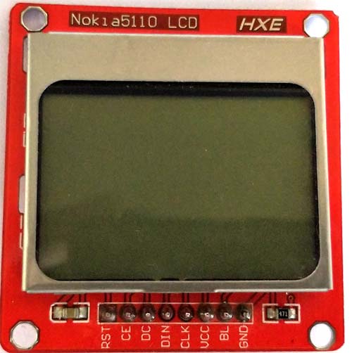
Here the Nokia 5110 LCD is used to display the Light level and distance. The Nokia 5110 LCD operates at 3.3V so it can’t be connected with Arduino Nano digital pins directly. So add 10k resistors in series with the data signals to protect the 3.3V lines from 5V digital pins. Learn more about using Nokia 5110 LCD with Arduino.
The VL6180 Sensor can be directly connected to the Arduino. The communication between the VL6180and Arduino is I2C. Actually I2C communication protocol combines the best features of SPI and UART. Here we can connect multiple slaves to a single master and we can have multiple masters controlling single or multiple slave. Like UART communication, I2C uses two wires for communication SDA (Serial Data) and SCL (Serial Clock), a data line and clock line.
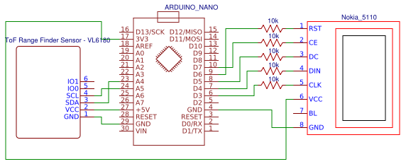
Circuit diagram for connecting VL6180 ToF Range Finder Sensor with Arduino is shown below:

- Connect the RST Pin of LCD to the pin 6 of Arduino through the 10K resistor.
- Connect the CE Pin of LCD to the pin 7 of Arduino through the 10K resistor.
- Connect the DC Pin of LCD to the pin 5 of Arduino through the 10K resistor.
- Connect the DIN Pin of LCD to the pin 4 of Arduino through the 10K resistor.
- Connect the CLK Pin of LCD to the pin 3 of Arduino through the 10K resistor.
- Connect the VCC Pin of LCD to the 3.3V pin of Arduino.
- Connect the GND Pin of LCD to the GND of Arduino.
- Connect the SCL pin of VL6180 to A5 pin of Arduino
- Connect the SDA pin of VL6180 to A4 pin of Arduino
- Connect the VCC pin of VL6180 to 5V pin of Arduino
- Connect the GND pin of VL6180 to GND pin of Arduino
Adding required Libraries for VL6180 ToF Sensor
Three libraries will be used in interfacing VL6180 sensor with Arduino.
1. Adafruit_PCD8544
Adafruit_PCD8544 is a library for the Monochrome Nokia 5110 LCD Displays. These displays use SPI for communication. Four or five pins are required for interfacing this LCD. The link for download this library is given below:
https://github.com/adafruit/Adafruit-PCD8544-Nokia-5110-LCD-library/archive/master.zip
2. Adafruit_GFX
The Adafruit_GFX library for Arduino is the core graphics library for LCD displays, providing a common syntax and set of graphics primitives (points, lines, circles, etc). It needs to be paired with a hardware specific library for each display device we use (to handle the lower level functions). The link for download this library is given below:
https://github.com/adafruit/Adafruit-GFX-Library
3. SparkFun VL6180
SparkFun_VL6180 is the Arduino library with basic functionality of the VL6180 sensor. The VL6180 consists of an IR emitter, a range sensor, and an ambient light sensor which communicate via an I2C interface. This library allows you to read the distance and light outputs from the sensor, and outputs the data via a serial connection. The link for download this library is given below:
http://downloads.arduino.cc/libraries/github.com/sparkfun/SparkFun_VL6180_Sensor-1.1.0.zip
Add all the libraries one by one by going into Sketch>>Include library>>Add .ZIP library in Arduino IDE. Then upload the library that you downloaded from the above links.

Sometimes you won’t need to add wire and SPI libraries, but if you are getting an error please download and add them to your Arduino IDE.
https://github.com/PaulStoffregen/SPI
https://github.com/PaulStoffregen/Wire
Programming and Working Explanation
Complete code with a working video is given at the end of this tutorial, here we are explaining the complete program to understand the working of the project.
In this program majority of the parts are handled by the libraries that we added so you do not need to worry about that.
In the setup parts set the baud rate as 115200 and initialize the Wire library for I2C. Then check whether the VL6180 sensor is working properly or not, if it is not working then show an error message.
In the following part we are setting up the display, you can change the contrast to your desired value here I am setting it as 50
void setup()
{
  Serial.begin(115200); //Start Serial at 115200bps
  Wire.begin(); //Start I2C library
  delay(100); // delay .
  if (sensor.VL6180xInit() != 0) {
    Serial.println("FAILED TO INITALIZE"); //Initialize device and check for errors
  };
 sensor.VL6180xDefautSettings(); //Load default settings to get started.
  delay(1000); // delay 1s
 display.begin();
  // init done
  // you can change the contrast around to adapt the display
  // for the best viewing!
  display.setContrast(50);
 display.display(); // show splashscreen
 display.clearDisplay();
}
In the void loop part setup the instructions to display the values on LCD screen. Here we are displaying two values, one is the “Ambient light level in Lux” (One lux is actually one lumen per square meter area), and second one is “Distance measured in mm”. To display different values on a LCD screen define the position of each text that should display on the LCD screen by using “display.setCursor(0,0);”.
void loop()
{
  display.clearDisplay();
  //Get Ambient Light level and report in LUX
  Serial.print("Ambient Light Level (Lux) = ");
  Serial.println(sensor.getAmbientLight(GAIN_1));
  display.setTextSize(1);
  display.setTextColor(BLACK);
  display.setCursor(0,0 );
  display.println("Light Level");
  display.setCursor(0,12);
  display.println(sensor.getAmbientLight(GAIN_1));
  //Get Distance and report in mm
 Serial.print("Distance measured (mm) = ");
  Serial.println(sensor.getDistance());
  display.setTextSize(1);
  display.setTextColor(BLACK);
  display.setCursor(0, 24);
  display.println("Distance(mm)=");
  display.setCursor(0, 36);
  b = sensor.getDistance();
  display.println(b);
  display.display();
  delay(500);
}
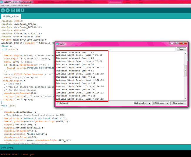
After uploading the program, open the serial monitor and it should show the output as shown below.
The VL6180 TOF range finders are used in smartphones, portable touchscreen devices, Tablet, laptop, gaming devices and Domestic appliances/industrial devices.
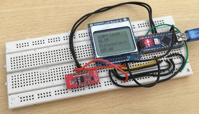
Here we are displaying the Ambient light level in Lux and distance in mm.

Find the complete program and demonstration Video below. Also check how to measure distance using Ultrasonic sensor and light level using BH1750 Ambient Light Sensor.
Complete Project Code
#include <SPI.h>
#include <Adafruit_GFX.h>
#include <Adafruit_PCD8544.h>
#include <Wire.h>
#include <SparkFun_VL6180X.h>
#define VL6180X_ADDRESS 0x29
VL6180x sensor(VL6180X_ADDRESS);
Adafruit_PCD8544 display = Adafruit_PCD8544(3, 4, 5, 7, 6);
float b;
void setup()
{
  Serial.begin(115200); //Start Serial at 115200bps
  Wire.begin(); //Start I2C library
  delay(100); // delay .
  if (sensor.VL6180xInit() != 0) {
    Serial.println("FAILED TO INITALIZE"); //Initialize device and check for errors
  };
  sensor.VL6180xDefautSettings(); //Load default settings to get started.
  delay(1000); // delay 1s
 display.begin();
  // init done
  // you can change the contrast around to adapt the display
  // for the best viewing!
  display.setContrast(50);
 display.display(); // show splashscreen
 display.clearDisplay();
}
void loop()
{
  display.clearDisplay();
  //Get Ambient Light level and report in LUX
  Serial.print("Ambient Light Level (Lux) = ");
  Serial.println(sensor.getAmbientLight(GAIN_1));
  display.setTextSize(1);
  display.setTextColor(BLACK);
  display.setCursor(0,0 );
  display.println("Light Level");
  display.setCursor(0,12);
  display.println(sensor.getAmbientLight(GAIN_1));
  //Get Distance and report in mm
 Serial.print("Distance measured (mm) = ");
  Serial.println(sensor.getDistance());
  display.setTextSize(1);
  display.setTextColor(BLACK);
  display.setCursor(0, 24);
  display.println("Distance(mm)=");
  display.setCursor(0, 36);
  b = sensor.getDistance();
  display.println(b);
  display.display();
  delay(500);
}

Hi Pradeep, a very nice project. Do you know of senros that can provide a longer range than 25cm? Say, 1m?