")
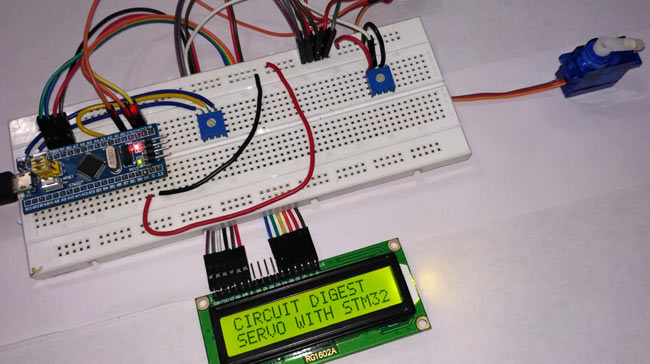
In electronics, Servo motors are mostly used in Robotics Projects because of their accuracy and easy handling. Servo motors are smaller in size and they are very effective and energy efficient. They provide high torque and can be used to lift or push weights according to motors specification. In this tutorial we will learn about Servo Motor and How to interface Servo with STM32F103C8 board. A potentiometer is also interfaced to vary the position of the servo motor’s shaft, and a LCD to display the angle value.
Components Required
- STM32F103C8 (Blue Pill) Board
- Servo Motor (SG90)
- LCD(16x2)
- Potentiometer
- Breadboard
- Jumper Wires
Circuit Diagram and Connections
")
SMT32F103C8 Pin Details
In STM32F103C8, we have 10 ADC pins (PA0-PB1), and here we use only one pin (PA3) for analogread() for setting shaft position of motor by potentiometer. Also among 15 PWM pins of STM32 (PA0, PA1, PA2, PA3, PA6, PA7, PA8, PA9, PA10, PB0, PB1, PB6, PB7, PB8, PB9), one pin will be used for providing pulses to the Servo motor’s PWM pin(usually it is orange in colour).
You can learn more about PWM and ADC by reading below to detailed articles:
Connection between STM32F103C8 and LCD
| STM32F103C8 | LCD |
| GND | VSS |
| +5V | VDD |
| To Potentiometer Centre PIN | V0 |
| PB0 | RS |
| GND | RW |
| PB1 | E |
| PB10 | D4 |
| PB11 | D5 |
| PC13 | D6 |
| PC14 | D7 |
| +5V | A |
| GND | K |
Connection between Servo motor and STM32F103C8
|
STM32F103C8 |
SERVO |
|
+5V |
RED (+5V) |
|
PA0 |
ORANGE (PWM pin) |
|
GND |
BROWN (GND) |
Potentiometers Connections
We have used TWO potentiometers here
1. The potentiometer on the right is used to vary the LCD contrast. It has three pins, left pin is for +5V and right is for GND and centre pin is connected to V0 of the LCD.
2. The potentiometer on the left is used to vary the shaft position of servo motor by controlling the analog input voltage, the left pin has input 3.3V and right has GND and centre output is connected to (PA3) of STM32
Programming STM32 for Servo Motor
Like our previous tutorial, we programmed the STM32F103C8 with Arduino IDE through USB port without using FTDI programmer. We can proceed programming it like an Arduino. Complete code is given below at the end of project.
First we have included library files for servo and LCD functions:
#include<Servo.h>
#include<LiquidCrystal.h>
Then declared pins for LCD display and initialized it. Also declared few other variables for PWM and potentiometer:
const int rs = PB0, en = PB1, d4 = PB10 , d5 = PB11 , d6 = PC13, d7 = PC14;
LiquidCrystal lcd(rs,en,d4,d5,d6,d7);
int servoPin = PA0;
int potPin = PA3;
Here we have created variable servo with datatype Servo and attached it to previously declared PWM pin.
Servo servo;
servo.attach(servoPin);
Then read Analog value from pin PA3 as it is a ADC pin it converts analog voltage (0-3.3) into digital form (0-4095)
analogRead(potPin);
As the digital output is 12-bit resolution, we need to get values in range of degree (0-170), it divides ADC (0-4096) value according to max angle 170 deg so we divide with 24.
angle = (reading/24);
Below statement makes the servo motor to rotate the shaft at angle given.
servo.write(angle);
Complete code is given below and well explained by comments.
Complete Project Code
//INTERFACE SERVO WITH STM32

//CIRCUIT DIGEST
#include<Servo.h>                                                          //including servo library

#include<LiquidCrystal.h>                                               //including LCD display library

const int rs = PB0, en = PB1, d4 = PB10 , d5 = PB11 , d6 = PC13, d7 = PC14;   //declaring pin names and pin numbers of lcd

LiquidCrystal lcd(rs,en,d4,d5,d6,d7);                               //setting lcd and its paramaters
int servoPin = PA0;                                //declare and initialize pin for servo output PWM

int potPin = PA3;                                     //potentiometer ADC input
Servo servo;                                            // creating variable servo with datatype Servo
void setup()
{

  lcd.begin(16,2);                                                           //setting lcd as 16x2

  lcd.setCursor(0,0);                                                        //setting cursor at first row and first column

  lcd.print("CIRCUIT DIGEST");                                               //puts CIRCUIT DIGEST in LCD

  lcd.setCursor(0,1);                                                        //setting cursor at second row and first column

  lcd.print("SERVO WITH STM32");                                             //puts SERVO WITH STM32 in LCD

  delay(3000);                                                               // delays for 3 seconds

  lcd.clear();                                                               //clears lcd display

  servo.attach(servoPin);   //it connects pin PA0 with motor as control feedback by providing pulses


}
void loop()

{

 lcd.clear();                                                                 //clears lcd

 int angle;                                                                   //declare varible angle as int

 int reading;                                                                 //declare varible reading as int

 reading = analogRead(potPin);                                                //read analog value from pin PA3

 angle = (reading/24);                                                        //it divides ADC the value according to max angle 170 deg

 servo.write(angle);                                                          //it puts angle value at servo

 lcd.setCursor(0,0);                                                          //setting cursor at first row and first column

 lcd.print("ANGLE:");                                                         //puts ANGLE in LCD

 lcd.print(angle);                                                            //puts value at angle

 delay(100);                                                                  //delay in time

}

Hi author.
I'm new to electrict and i'm following your article but i don't know where to get Servo.h, can you give me an advice to get it?
thankyou.