

The reliability of any electronic device depends on how well the hardware protection circuits have been designed. The end user (consumer) is prone to make mistakes and it is the responsibility of a good hardware designer to protect his hardware from any mishappening. There are ample types of protection circuits each with its own specific applications. The most common type of protection circuits are Over Voltage protection circuit, Reverse Polarity Protection Circuit, Current surge Protection and Noise protection circuits. In this tutorial we will discuss about the Crowbar Circuit which is a type of overvoltage protection circuit and is commonly used in electronic devices. We will also practically create this circuit and verify how it is working in real life.
Materials Required
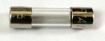
- Fuse
- Zener Diode
- Thyristor
- Capacitors
- Resistors
- Schottky Diode
Crowbar Circuit Diagram
The circuit diagram of a crowbar circuit is very simple and easy to build and implement making it a cost effective and quick solution. The complete crowbar circuit diagram is shown below.

Here the input voltage (blue probe) is the voltage which has to be monitored and the circuit is designed to cut off the supply when the supply voltage exceeds 9.1V. We will discuss the function of every component in the working section below.
Working of Crowbar Circuit
A Crowbar circuit monitors the input voltage and when it exceeds the limit it creates a short circuit across the power lines and blows up the fuse. Once the fuse is blown the power supply will be disconnected from the load and thus preventing it from high voltage. The circuit works by creating a direct short circuit across the power lines, as if a crowbar is dropped between power lines of the circuit. Hence it gets its iconic name crowbar circuit.
The voltage over which the circuit should create a short depends on the Zener voltage. The circuit consists of a SCR which is directly connected across the Input voltage and ground of the circuit, but this SCR is by default kept in turned off state by grounding the gate pin of the SCR. When the Input voltage exceeds the Zener voltage the Zener diode begins to conduct and hence a voltage is supplied to the Gate pin of the SCR making it to close the connection between the Input Voltage and Ground thus creating a short circuit. This short circuit will draw a maximum current from the power supply and blow up the fuse isolating the power supply form the load. The complete working can also be easily understood by looking at the GIF image above. You can also find a Demonstration Video at the end of this tutorial.
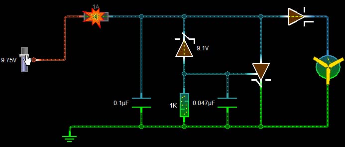
The above image represents how the crowbar circuit responds exactly when the over-voltage condition occurs. As you can see the Zener Diode here is rated for 9.1V but the input voltage has exceeds the value and is currently at 9.75V. So the Zener Diode opens and begins to conduct by providing a voltage to the Gate pin of the SCR. The SCR then begins to conduct by shorting the Input voltage and Ground and thus blows up the fuse due to maximum current draw as shown in GIF above. The function of each component in this circuit is explained below.
Fuse: The fuse is the vital component in this circuit. The rating of the fuse should always be less than the maximum current rating of the SCR and more than the current consumed by the load. We should also make sure that the Power supply can source enough current to break the fuse in event if failures.
0.1uF Capacitor: This is a filtering capacitor; it removes the spikes and other noise like harmonics from the supply voltage to prevent the circuit form false triggering.
9.1V Zener Diode: This diode decides the over voltage value, since here we have used a 9.1V Zener diode the circuit will respond to any voltage that is above its threshold value of 9.1V. The Designer can choose the value of this resistor according to his needs.
1K Resistor: This is just a pull down resistor which holds the Gate pin of the SCR to ground and thus keeping it turned off until the Zener begins to conduct.
47nF Capacitor: Every Power switch like SCR requires a snubber circuit to suppress the voltage spikes during switching and prevent the SCR from false triggering. Here we have just used a capacitor to do the job. The value of the capacitor should be just enough to filter the noise, because high value of capacitance will increase the delay at which the SCR begins to conduct after applying the Gate pulse.
Thyristor (SCR): The Thyristor is responsible for creating a short circuit across the power rails. Care should be taken so that the SCR can handle such high value of current through it to blow the fuse and damage itself. The Gate voltage of the SCR should be less than the Zener breakdown voltage. Learn more about Thyristor here.
Schottky Diode: This diode is not mandatory and is used only for protection purpose. It makes sure that we do not get any reverse current from the load side that could possibly damage the protection circuit. A Schottky diode is used instead of a regular diode because it has less voltage drop across it.
Hardware
Now that we have understood the theory behind the Crowbar circuit, it is time to get into the fun part. That is actually building the circuit in top of a bread board and check how it is working in real time. The circuit that I am building is for a 12V bulb. This bulb consumes about 650mA under normal operating voltage of 12V. We will design the crowbar circuit to check if the voltage exceeds the 12V and if it does we will short the SCR and thus blow out the fuse. So here I have used a 12V Zener diode and TYN612 Thyristor. The fuse is mounted inside a fuse holder, here we have used Cartridge Fuse of 500mA rating. The complete setup is shown in the picture below
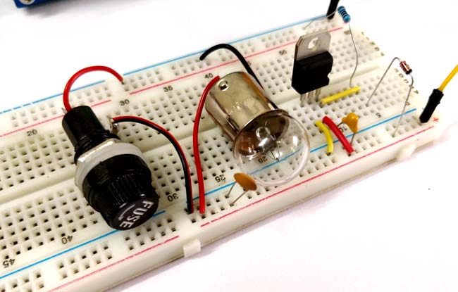
I have used an RPS to control the Input voltage, initially the setup is tested with 12V and it works fine by turning the bulb on. Later the voltage is raised using the RPS knob thus creating a short circuit through the SCR and blowing the fuse which also turns off the bulb and isolate it form the power supply. The complete working can also be checked in the video at the bottom of this page.
Limitations of Crowbar Circuit
Although the circuit is widely used it does come with its own limitations which are listed below
- The overvoltage value of the circuit depends purely upon the Zener voltage value, and only few values of Zener diode are available.
- The circuit is also subjected to noise problems; this noise can often create a false trigger and blow up the fuse.
- In event of overvoltage the circuit blows the fuse and later requires manual help to run the load again when the voltage gets normal.
- The fuse is a mechanical fuse which has to be replaced and hence consumes effort, time and money.

high resolution