

The first thing that comes in our mind listening to the word Joystick is the game controller. Yes, it’s exactly the same and can be used for gaming purpose. Apart from gaming, it has many other applications in DIY electronics. This joystick is nothing but a combination of two potentiometers for X and Y plane respectively. It reads the voltage through the potentiometer and gives analog value to the Arduino, and the analog value changes as we move the joystick shaft (which is simply the potentiometer pointer).
In this Circuit, we are interfacing Joystick with Arduino simply by controlling four LEDs as per the movement of the Joystick. We have placed 4 LEDs in such a way that it represents the direction of the joystick shaft movement. This joystick also has a push button which can be used for various other purposes or can be left idle. A single LED is also attached to the switch of the joystick, as the joystick button pressed that single LED will turn ON.
Material Required
- Arduino UNO
- Joystick Module
- LEDs-5
- Resistor: 100ohm-3
- Connecting wires
- Breadboard
Circuit Diagram

Joystick Module
Joysticks are available in different shapes and sizes. A typical Joystick module is shown in the figure below. This Joystick module typically provides Analog Outputs and the output voltages provided by this module keep changing according to the direction in which we move it. And we can get the direction of movement by interpreting these voltage changes using some microcontroller. Previously we interfaced Joystick with AVR and Raspberry Pi.
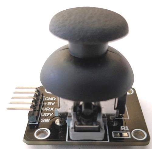
This joystick module has two axes as you can see. They are X-axis and Y-axis. Each axis of JOYSTICK is mounted to a potentiometer or pot. The midpoints of these pots are driven out as Rx and Ry. So Rx and Ry are variable points to these pots. When the Joystick is in standby, Rx and Ry act as a voltage divider.
When the joystick is moved along the horizontal axis, the voltage at Rx pin changes. Similarly, when it is moved along the vertical axis, the voltage at Ry pin changes. So we have four directions of Joystick on two ADC outputs. When the stick is moved, the voltage on each pin goes high or low depending on direction.
Here, we are connecting this Joystick module with the Arduino UNO which comes with an inbuilt ADC (Analog to Digital Converter) mechanism as shown in the video at the end. Learn more about using Arduino’s ADC here.
Code and Explanation
Complete Arduino Code is mentioned at the end.
In below code, we have defined X and Y axis of the Joystick module for analog pin A0 and A1 respectively.
#define joyX A0
#define joyY A1
Now, in the below code, we are initializing PIN 2 of Arduino for the Switch (push button) of the Joystick module and the value of buttonstate and buttonstate1 will be 0 at the start.
int button=2;
int buttonState = 0;
int buttonState1 = 0;
In the below code, we are setting up the baud rate to 9600 and defined Pin 7 as an output pin and button pin as an input Pin. Initially, the button pin will remain high until the Switch will press.
void setup() {
  pinMode(7,OUTPUT);
  pinMode(button,INPUT);
  digitalWrite(button, HIGH);
  Serial.begin(9600);
}
Here, in this code we are reading the values from the analog pin A0 and A1 and printing serially.
int xValue = analogRead(joyX);
int yValue = analogRead(joyY);

  Serial.print(xValue);
  Serial.print("\t");
  Serial.println(yValue);
The conditions, for turning LED on and off as per the movement of the Joystick shaft, are defined in the code below. Here we are just taking analog values of voltage at pin A0 and A1 of Arduino. These analog values will change as we move the joystick and LED will glow according to movement of joystick.

This condition is for movement of Joystick shaft in -Y axis direction
 if (xValue>=0 && yValue<=10){
    digitalWrite(10, HIGH);
  }
  else{digitalWrite(10, LOW);}
This condition is for movement of Joystick shaft in -X axis direction
  if (xValue<=10 && yValue>=500){
    digitalWrite(11, HIGH);
  }
  else{digitalWrite(11, LOW);}
This condition is for movement of Joystick shaft in +X axis direction
  if (xValue>=1020 && yValue>=500){
    digitalWrite(9, HIGH);
  }
  else{digitalWrite(9, LOW);}
This condition is for movement of Joystick shaft in +Y axis direction
  if (xValue>=500 && yValue>=1020){
    digitalWrite(8, HIGH);
  }
  else{digitalWrite(8, LOW);}
When we move the joystick shaft diagonally then one position come when the analog value of X and Y will be 1023 and 1023 respectively, both Pin 9 and Pin 8 LED will glow. Because it satisfies the condition of the LED. So, for removing that mismatch we have given a condition that if the value of (X, Y) is (1023, 1023) then both the LED remain in OFF condition
  if (xValue>=1020 && yValue>=1020)  {
    digitalWrite(9, LOW);
    digitalWrite(8, LOW);
  }
The below condition is used to operate the LED connected to the Pushbutton Switch. As we press the Joystick switch the LED will turn ON and latch until the button release. Its optional to use the Push button switch on Joystick module.
  if (buttonState == LOW)  {
    Serial.println("Switch = High");
    digitalWrite(7, HIGH);
  }
  else{digitalWrite(7, LOW);}
Controlling LEDs using Joystick with Arduino

After uploading the code to the Arduino and connect the components as per the circuit diagram, we can now control the LEDs with Joystick. We can turn ON the four LEDs in each direction as per the Joystick shaft movement. The Joystick is having two potentiometer inside it, one is for X-axis movement and another is for Y-axis movement. Each potentiometer is getting 5v from the Arduino. So as we move the joystick, the voltage value will change and the analog value at Analog pins A0 and A1 will also change.
So, from the Arduino, we are reading the analog value for X and Y axis and turning ON the LEDs as per the axis movement of the Joystick. A push button switch on Joystick module is used to control the single LED in the circuit as shown in the video below.
Complete Project Code
#define joyX A0

#define joyY A1
int button=2;

int buttonState = 0;

int buttonState1 = 0;
void setup() {

  pinMode(7,OUTPUT);

  pinMode(button,INPUT);

  digitalWrite(button, HIGH);

  Serial.begin(9600);

}


void loop() {

 int xValue = analogRead(joyX);

 int yValue = analogRead(joyY);


  Serial.print(xValue);

  Serial.print("\t");

  Serial.println(yValue);


  buttonState = digitalRead(button);

  Serial.println(buttonState);

  if (xValue>=0 && yValue<=10)

  {

    digitalWrite(10, HIGH);

  }

  else{digitalWrite(10, LOW);}
  if (xValue<=10 && yValue>=500)

  {

    digitalWrite(11, HIGH);

  }

  else{digitalWrite(11, LOW);}
  if (xValue>=1020 && yValue>=500)

  {

    digitalWrite(9, HIGH);

  }

  else{digitalWrite(9, LOW);}
  if (xValue>=500 && yValue>=1020)

  {

    digitalWrite(8, HIGH);

  }

  else{digitalWrite(8, LOW);}
  if (xValue>=1020 && yValue>=1020)

  {

    digitalWrite(9, LOW);

    digitalWrite(8, LOW);

  }
  if (buttonState == LOW)

  {

    Serial.println("Switch = High");

    digitalWrite(7, HIGH);

  }

  else{digitalWrite(7, LOW);}

  buttonState1 = digitalRead(7);

  Serial.println(buttonState1);

  delay(50);

}
Comments
Thanks for the heads up, yes
Thanks for the heads up, yes the pin declaration in missing in the program
hi there, how do I update
hi there, how do I update thie code as per your comment?
I've
In the void setup function
In the void setup function replace
pinMode(7,OUTPUT);
With
pinMode(7,OUTPUT);
pinMode(8,OUTPUT);
pinMode(9,OUTPUT);
pinMode(10,OUTPUT);
What do you wanna fix?
What do you wanna fix? Elaborate your problem if at all you are seeking any solution from other. Because only if some knows your problem they can help you
Just reduce the value of
Just reduce the value of current limiting resistors attached to the LED and thwn the LED will be brighter
Just change the pins and
Just change the pins and declare them properly it should work

This code didn't work for my ,because you forgot to set the LED pins 8,9,10 and 11 as an Output
Beside that I found it a nice educational project.