
Robots are playing an important role in automation across all the sectors like construction, military, medical, manufacturing, etc. After making some basic robots like line follower robot, computer controlled robot, etc, we have developed this accelerometer based gesture controlled robot by using arduino uno. In this project we have used hand motion to drive the robot. For this purpose we have used accelerometer which works on acceleration.
Required Components
- Arduino UNO
- DC Motors
- Accelerometer
- HT12D
- HT12E
- RF Pair
- Motor Driver L293D
- 9 Volt Battery
- Battery Connector
- USB cable
- Robot Chasis
RF Pair:
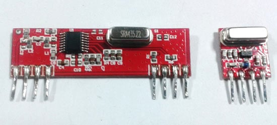
A gesture controlled robot is controlled by using hand in place of any other method like buttons or joystick. Here one only needs to move hand to control the robot. A transmitting device is used in your hand which contains RF Transmitter and accelero-meter. This will transmit command to robot so that it can do the required task like moving forward, reverse, turning left, turning right and stop. All these tasks will be performed by using hand gesture.
Here the most important component is accelerometer. Accelerometer is a 3 axis acceleration measurement device with +-3g range. This device is made by using polysilicon surface sensor and signal conditioning circuit to measure acceleration. The output of this device is Analog in nature and proportional to the acceleration. This device measures the static acceleration of gravity when we tilt it. And gives an result in form of motion or vibration.
According to the datasheet of adxl335 polysilicon surface-micromachined structure placed on top of silicon wafer. Polysilicon springs suspend the structure over the surface of the wafer and provide a resistance against acceleration forces. Deflection of the structure is measured using a differential capacitor which incorporate independent fixed plates and plates attached to the moving mass. The fixed plates are driven by 180° out-of-phase square waves. Acceleration deflects the moving mass and unbalances the differential capacitor resulting in a sensor output whose amplitude is proportional to acceleration. Phase-sensitive demodulation techniques are then used to determine the magnitude and direction of the acceleration.
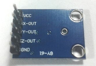
Pin Description of accelerometer
- Vcc 5 volt supply should connect at this pin.
- X-OUT This pin gives an Analog output in x direction
- Y-OUT This pin give an Analog Output in y direction
- Z-OUT This pin gives an Analog Output in z direction
- GND Ground
- ST This pin used for set sensitivity of sensor
Circuit Diagram and Explanation
Gesture Controlled Robot is divided into two sections:
- Transmitter part
- Receiver part
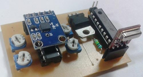
In transmitter part an accelerometer and a RF transmitter unit is used. As we have already discussed that accelerometer gives an analog output so here we need to convert this analog data in to digital. For this purpose we have used 4 channel comparator circuit in place of any ADC. By setting reference voltage we gets a digital signal and then apply this signal to HT12E encoder to encode data or converting it into serial form and then send this data by using RF transmitter into the environment.
At the receiver end we have used RF receiver to receive data and then applied to HT12D decoder. This decoder IC converts received serial data to parallel and then read by using arduino. According to received data we drive robot by using two DC motor in forward, reverse, left, right and stop direction.
Working
Gesture controlled robot moves according to hand movement as we place transmitter in our hand. When we tilt hand in front side, robot start to moving forward and continues moving forward until next command is given.
When we tilt hand in backward side, robot change its state and start moving in backwards direction until other command is given.
When we tilt it in left side Robot get turn left till next command.
When we tilt hand in right side robot turned to right.
And for stopping robot we keeps hand in stable.

Circuit Diagram for Transmitter Section

Circuit Diagram for Receiver Section
Circuit for this hand gesture controlled robot is quite simple. As shown in above schematic diagrams, a RF pair is used for communication and connected with arduino. Motor driver is connected to arduino to run the robot. Motor driver’s input pin 2, 7, 10 and 15 is connected to arduino digital pin number 6, 5, 4 and 3 respectively. Here we have used two DC motors to drive robot in which one motor is connected at output pin of motor driver 3 and 6 and another motor is connected at 11 and 14. A 9 volt Battery is also used to power the motor driver for driving motors.
Program Explanation
In program first of all we have defined output pins for motors.

And then in setup we have given the directions to pin.

After this we read input by using ‘if statement’ and perform relative operation.

There are total five conditions for this Gesture controlled Robot which are giving below:
|
Movement of hand |
Input for Arduino from gesture |
||||
|
Side |
D3 |
D2 |
D1 |
D0 |
Direction |
|
Stable |
0 |
0 |
0 |
0 |
Stop |
|
Tilt right |
0 |
0 |
0 |
1 |
Turn Right |
|
Tilt left |
0 |
0 |
1 |
0 |
Turn Left |
|
Tilt back |
1 |
0 |
0 |
0 |
Backward |
|
Tilt front |
0 |
1 |
0 |
0 |
Forward |
We have writen the complete program according to the above table conditions. Below is the complete code.
Complete Project Code
#define FD 16

#define BD 17

#define LD 18

#define RD 19
#define m11 3

#define m12 4

#define m21 5

#define m22 6
void forward()

{

   digitalWrite(m11, HIGH);

   digitalWrite(m12, LOW);

   digitalWrite(m21, HIGH);

   digitalWrite(m22, LOW);

}
void backward()

{

   digitalWrite(m11, LOW);

   digitalWrite(m12, HIGH);

   digitalWrite(m21, LOW);

   digitalWrite(m22, HIGH);

}
void left()

{

   digitalWrite(m11, HIGH);

   digitalWrite(m12, LOW);

   digitalWrite(m21, LOW);

   digitalWrite(m22, LOW);

}
void right()

{

   digitalWrite(m11, LOW);

   digitalWrite(m12, LOW);

   digitalWrite(m21, HIGH);

   digitalWrite(m22, LOW);

}
void Stop()

{

   digitalWrite(m11, LOW);

   digitalWrite(m12, LOW);

   digitalWrite(m21, LOW);

   digitalWrite(m22, LOW);

}
void setup()

{

  pinMode(FD, INPUT);

  pinMode(BD, INPUT);

  pinMode(LD, INPUT);

  pinMode(RD, INPUT);
  pinMode(m11, OUTPUT);

  pinMode(m12, OUTPUT);

  pinMode(m21, OUTPUT);

  pinMode(m22, OUTPUT);

}
void loop()

{
  int temp1=digitalRead(FD);

  int temp2=digitalRead(BD);

  int temp3=digitalRead(LD);

  int temp4=digitalRead(RD);


  if(temp1==1 && temp2==0 && temp3==0 && temp4==0)

  backward();
  else if(temp1==0 && temp2==1 && temp3==0 && temp4==0)

  forward();
  else if(temp1==0 && temp2==0 && temp3==1 && temp4==0)

  left();
  else if(temp1==0 && temp2==0 && temp3==0 && temp4==1)

  right();
  else

  Stop();

}
Comments
please give me the correct
please give me the correct program code of gesture controled robot using arduino using accelerometer ,is 3 wheeled robot move in all directions
Pcb layout
Pls send me pcb layout of transmiter and receiver
I have project submission in few days
Tried alot but not completed.
Kindly do help
about accelerometer based robot
i can't find some component on proteus to make simulation can anyone mail me the simulation file .plz help me.
regarding accelerometer
plz tell me how to find x,y,z axis pin on accelerometer.
It is mentioned on the
It is mentioned on the acclerometer module itself, check this image: https://circuitdigest.com/sites/default/files/inlineimages/Accelerometer.jpg
Can i remove arduino and
Can i remove arduino and directly connect o/p of decoder ic to i/p of motor driver ic as in your rf controlled robot?
replacement
can we replace the present transmitter and receiver with nrf24l01?
what are the changes in the present circuit if we replace with it?
Learn more about connecting
Learn more about connecting NRF modules with arduino in this tutorial: Create a Private Chat Room using Arduino, nRF24L01 and Processing
Need Proteus design file
Please give me the Proteus design file .ASM file....
please give me the pcb layout
please give me the pcb layout of the transmitter and receiver circuit.
Lot of Doubts
Hey Man,
I loved this design. But, I have some doubts. i believe you can help me by sorting things out.
How many Operational Amplifiers am I supposed to use. Is it four?
Have some more doubts too. But, I believe I can sort some of them myself.
Please reply.
Four Op-amp, as shown in
Four Op-amp, as shown in circuit diagram.
I have connected all the
I have connected all the components asper the circuit, when I tilt the accelerometer forward and right the motors moves forward and right, but when I tilt it to left and backwards direction the motors aren't running!! please help me out! what should I do??
The code is in c++ r only c
The code is in c++ r only c plz tell me and how to compile it in arduino please help me??
Pcb layout
Hi
Can u plzz give me the PCB layout of both transmitting and receiving circuits please reply me as early as possible
Hello! i have a adxl345
Hello! i have a adxl345 accelerometer instead of adxl335 ..what is the difference and how should i go about?
I think since both have the
I think since both have the same pin-out it should be very different
I am making this as my final
I am making this as my final project for assembly can u please help me for that
bug in the code
I even tried with the code you gave but the motors will not move.
Did you check your circuit.
Did you check your circuit. You cannot expect the project to start work straight away. Every project will need some level debugging this is where we actually learn things. Also when you a questions make sure you ask it clearly. What problem are you facing?
Pins on the arduino
#define FD 16
#define BD 17
#define LD 18
#define RD 19
please tell me which pins they are on th arduino uno
accelerometer
Hi.can i replace the adxl345 acceleromter with adxl335...
Related to the Hand gesture robot project
Hi Abhishek, Could you please tell me how have you added the RF module and Accelerometer in proteus while simulating as I am not able to find/add one. I urgently need it as I have to include the same in my BE project. Kindly help me for the same.
how do we know which position
how do we know which position is stable for the pot???
Need help regarding your accelerometer based hand gesture robot
Hello , I liked your project very much . So I decided to make it. I have made it just similar to yours even the coding are same, but am getting a problem.
The led on the receiver is blinking when am transmitting my data ,..but the MOTORs(the robot) are not moving at all.
I tried many thing but its not working.
So can you please help me
Am hoping for an positive reply ...please reply with ur solutions
Thank you.
use multimeter and check if
use multimeter and check if that particular pin is getting high (+5V). If yes the problem is on the motor driver side
motors are not running
i have used the same programme and circuit but motors are not running ..can u help me out please
How output in the form of X,Y
How output in the form of X,Y,Z is converted into 4 direction??
No the accelerometer will not
No the accelerometer will not blink during functioning. Use the serial debugger on Arduino to check if you are getting any values at all. What do you mean by not working? What problem are you facing? Only if you explain your problem in brief people here might be able to help you
Do you need to include any
Do you need to include any library for this?
Hi! I need some help because
Hi! I need some help because my LED does not blink so I dont know if there is any transmission and reception. I checked my connections and all of it is the same in the given diagram. Hoping for your reply thank you!
Projecet is not working
I think this project is fake I made all the things according to circuit diagram but nothing is working.
Blunder of mine was that I don't read comments.Please....don't make this project.
Arduino not powering up
Sir, I'm using an Arduino Nano for this project. I have made the connections as shown in the circuit diagram (I checked the connections 5 times). I shorted pins 1, 9 and 16 and connected the positive terminal of the 9v battery to pin 8 of L293D but the Arduino doesn't switch on. However, if I directly connect the battery to Vin pin of the Arduino, it switches on.
Can I directly power up the Arduino by connecting the battery to Vin pin of the Arduino,or is it mandatory to power up the Arduino using pin 8?
If so, would you mind helping me out with the power supply to the Arduino?
Thank you.
Can we use higher…
Can we use higher resistances than the ones we in the diagram?

#define FD 16
#define BD 17
#define LD 18
#define RD 19
this code correct or wrong because no pins in arduino like 16,17,18,19
anolog input like a1,a2,a3,a4