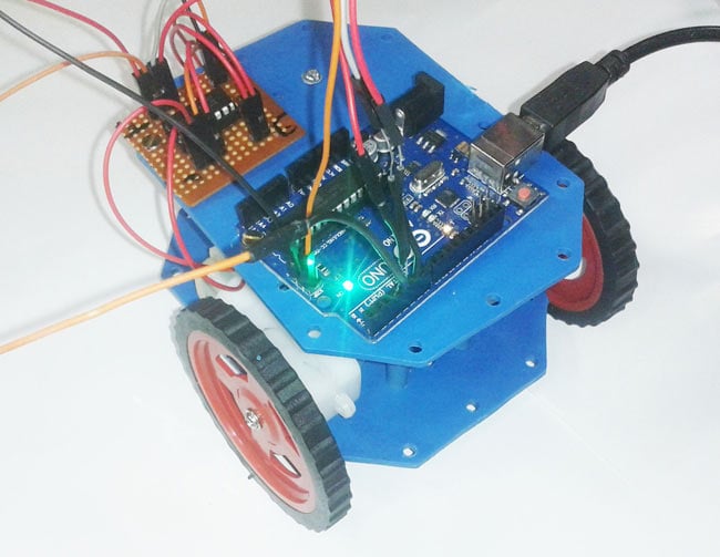
After designing this line follower robot using arduino uno, I have developed this computer controlled robot. It can be controlled via the computer and we can use specific keyboard keys to move it. It runs over serial communication which we have already discussed in our previous project - PC Controlled Home Automation.
Components Required
- Arduino UNO
- DC Motor
- Laptop
- Motor Driver L293D
- 9 Volt Battery
- Battery Connector
- USB cable
- Robot Chasis
Concepts and Details
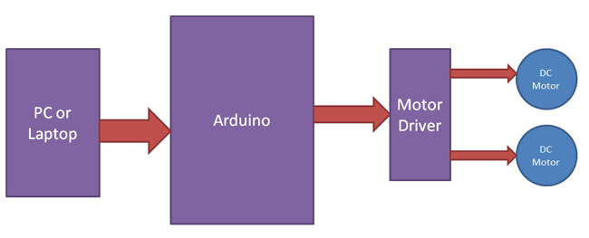
We can divide this PC controlled robot circuit into different segments and they are - sensor section, control section and driver section. Let us see them separately.
Command or PC section: This section has a serial communication device like PC, laptop etc. Here in this project we have used a laptop for demonstration. We sends command to arduino by typing a character on hyper terminal or any other serial terminal like hyper terminal, Hercules, putty, arduino’s serial terminal etc.

Control Section: Arduino UNO is used for controlling whole the process of robot. Arduino reads commands sent by laptop and compare with defined characters or commands. If commands are matched, arduino sends appropriate command to driver section.
Driver section: driver section consists a L293D motor driver IC and two DC motors. Motor driver is used for driving motors because arduino does not supply enough voltage and current to motor. So we add a motor driver circuit to get enough voltage and current for motor. By collecting commands from arduino, motor driver drives motors according to commands.
Working
We have programmed the PC controlled robot to run by some commands that are send via serial communication to arduino from PC. (see programming section below)
When we press ‘f’ or ‘F’, robot start to move forward and moving continues until next command is given.
When we press ‘b’ or ‘B’, robot change his state and start moving in backward direction until any other command is given.
When we press ‘l’ or ‘L’, Robot gets turn left until the next command.
When we press ‘r” or ‘R’ robot turns to right.
And for stopping robot we give ‘s’ or ‘S’ command to arduino.
Circuit Diagram and Explanation
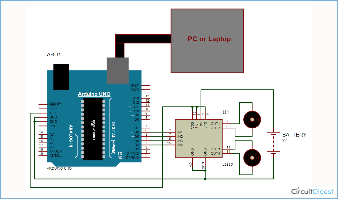
Circuit diagram for Arduino based PC controlled robot is shown in the above diagram. Only a motor driver IC is connected to arduino for running robot. For sending command to robot we used inbuilt serial data converter by using USB cable with laptop. Motor driver’s input pin 2, 7, 10 and 15 is connected at arduino digital pin number 6, 5, 4 and 3 respectively. Here we have used two DC motors to driver robot in which one motor is connected at output pin of motor driver 3 and 6 and another motor is connected at 11 and 14. A 9 volt Battery is used to power the motor driver for driving motors.
Program Explanation
In the programming first of all we have defined output pins for motors.
And then in setup we have given directions to pin and begin serial communication.
After that we read serial buffer by reading “serial.read()” function and get its value in to a temporary variable. And then match it with defined commands by using “if” statement to operate the robot.
There are four conditions to move this PC controlled Robot that are given in below table.
Input Commands | Output | Movement of Robot | ||||
|
| Left Motor
| Right Motor | |||
|
|
| ||||
S. | Stop | |||||
Turn Right | ||||||
Turn Left | ||||||
Backward | ||||||
Forward | ||||||
We have written the program according to above table conditions. Complete code is given below.
Complete Project Code
#define m11 3
#define m12 4
#define m21 5
#define m22 6
void setup()
{
  pinMode(m11, OUTPUT);
  pinMode(m12, OUTPUT);
  pinMode(m21, OUTPUT);
  pinMode(m22, OUTPUT);
  Serial.begin(9600);
}
void loop()
{
  while(Serial.available())
  {
    char In=Serial.read();

    if(In=='f' || In=='F')            // Forward
    {
      digitalWrite(m11, HIGH);
      digitalWrite(m12, LOW);
      digitalWrite(m21, HIGH);
      digitalWrite(m22, LOW);
    }

     else if(In=='b' || In=='B')            //backward
    {
      digitalWrite(m11, LOW);
      digitalWrite(m12, HIGH);
      digitalWrite(m21, LOW);
      digitalWrite(m22, HIGH);
    }

     else if(In=='l' || In=='L')     // Left
    {
      digitalWrite(m11, HIGH);
      digitalWrite(m12, LOW);
      digitalWrite(m21, LOW);
      digitalWrite(m22, LOW);
    }

     else if(In=='r' || In=='R')     // Right
    {
      digitalWrite(m11, LOW);
      digitalWrite(m12, LOW);
      digitalWrite(m21, HIGH);
      digitalWrite(m22, LOW);
    }

     else if(In=='s' || In=='S')    // stop
    {
      digitalWrite(m11, LOW);
      digitalWrite(m12, LOW);
      digitalWrite(m21, LOW);
      digitalWrite(m22, LOW);
    }

    else
    {

    }
  }
}
Comments
How much rpm motor you used? Please answer fast I am making this project


Which program you use to draw Circuit Diagram?