
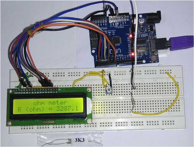
We find it difficult to read color codes on resistors to find its resistance. In order to overcome the difficulty of finding the resistance value, we are going to build a simple Ohm Meter using Arduino. The basic principle behind this project is a Voltage Divider Network. The value of the unknown resistance is displayed on 16*2 LCD display. This project also serves as 16*2 LCD display interfacing with Arduino.
Components Required:
- Arduino Uno
- 16*2 LCD display
- Potentiometer (1 kilo Ohm)
- Resistors
- Breadboard
- Jumper wires
Circuit Diagram:

Arduino Uno:
Arduino Uno is a open source microcontroller board based on ATmega328p microcontroller. It has 14 digital pins (out of which 6 pins can be used as PWM outputs), 6 analog inputs, on board voltage regulators etc. Arduino Uno has 32KB of flash memory, 2KB of SRAM and 1KB of EEPROM. It operates at the clock frequency of 16MHz. Arduino Uno supports Serial , I2C , SPI communication for communicating with other devices. The table below shows the technical specification of Arduino Uno.
| Microcontroller | ATmega328p |
| Operating voltage | 5V |
| Input Voltage | 7-12V (recommended) |
| Digital I/O pins | 14 |
| Analog pins | 6 |
| Flash memory | 32KB |
| SRAM | 2KB |
| EEPROM | 1KB |
|
Clock speed |
16MHz |
16x2 LCD:
16*2 LCD is a widely used display for embedded applications. Here is the brief explanation about pins and working of 16*2 LCD display. There are two very important registers inside the LCD. They are data register and command register. Command register is used to send commands such as clear display, cursor at home etc., data register is used to send data which is to be displayed on 16*2 LCD. Below table shows the pin description of 16*2 lcd.
|
Pin |
Symbol |
I/O |
Description |
|
1 |
Vss |
- |
Ground |
|
2 |
Vdd |
- |
+5V power supply |
|
3 |
Vee |
- |
Power supply to control contrast |
|
4 |
RS |
I |
RS=0 for command register , RS=1 for data register |
|
5 |
RW |
I |
R/W=0 for write , R/W=1 for read |
|
6 |
E |
I/O |
Enable |
|
7 |
D0 |
I/O |
8-bit data bus(LSB) |
|
8 |
D1 |
I/O |
8-bit data bus |
|
9 |
D2 |
I/O |
8-bit data bus |
|
10 |
D3 |
I/O |
8-bit data bus |
|
11 |
D4 |
I/O |
8-bit data bus |
|
12 |
D5 |
I/O |
8-bit data bus |
|
13 |
D6 |
I/O |
8-bit data bus |
|
14 |
D7 |
I/O |
8-bit data bus(MSB) |
|
15 |
A |
- |
+5V for backlight |
|
16 |
K |
- |
Ground |
Concept of Resistance Color Code:
To identify the value of the resistance we can use the below formula.
R= { (AB*10c)Ω ± T% }
Where
A = Value of the color in the first band.
B = Value of the color in the second band.
C = Value of the color in the third band.
T = Value of the color in the fourth band.
The table below shows the color code of resistors.
|
Color |
Numerical value of the color |
Multiplication factor(10c) |
Tolerance value(T) |
|
Black |
0 |
100 |
- |
|
Brown |
1 |
101 |
± 1% |
|
Red |
2 |
102 |
± 2% |
|
Orange |
3 |
103 |
- |
|
Yellow |
4 |
104 |
- |
|
Green |
5 |
105 |
- |
|
Blue |
6 |
106 |
- |
|
Violet |
7 |
107 |
- |
|
Gray |
8 |
108 |
- |
|
White |
9 |
109 |
- |
|
Gold |
- |
10-1 |
± 5% |
|
Silver |
- |
10-2 |
± 10% |
|
No band |
- |
- |
± 20% |
For example, if the color codes are Brown – Green – Red – Silver, the value of resistance is calculated as,
Brown = 1
Green = 5
Red = 2
Silver = ± 10%
From the first three bands, R = AB*10c
R = 15 * 10+2
R = 1500 Ω
Fourth band indicates tolerance of ± 10%
10% of 1500 = 150
For + 10 percent, the value is 1500 + 150 = 1650Ω
For - 10 percent, the value is 1500 -150 = 1350Ω
Therefore the actual resistance value can be anywhere between 1350Ω to 1650Ω.
To make it more convenient here is the Resistance Color Code Calculator where you only need enter the color of rings on resistor and you will get the resistance value.

Calculating Resistance using Arduino Ohm Meter:
The working of this Resistance Meter is very simple and can be explained using a simple voltage divider network shown below.
From the voltage divider network of resistors R1 and R2,
Vout = Vin * R2 / (R1 + R2 )
From the above equation, we can deduce the value of R2 as
R2 = Vout * R1 / (Vin – Vout)
Where R1 = known resistance
R2 = Unknown resistance
Vin = voltage produced at the 5V pin of Arduino
Vout = voltage at R2 with respect to ground.
Note: the value of known resistance (R1) chosen is 3.3KΩ, but the users should replace it with the resistance value of resistor they have chosen.
So if we get the value of voltage across unknown resistance (Vout), we can easily calculate the unknown resistance R2. Here we have read the voltage value Vout using the analog pin A0 (see the circuit diagram) and converted those digital values (0 -1023) into voltage as explained in Code below.
If the value of the known Resistance is far greater or smaller than the unknown resistance the error will be more. So it is advised to keep the known resistance value nearer to the unknown resistance.
Code explanation:
The complete Arduino program and Demo Video for this project is given at the end of this project. The code is split into small meaningful chunks and explained below.
In this part of the code, we are going to define the pins on which 16*2 LCD display is connected to Arduino. RS pin of 16*2 lcd is connected to digital pin 2 of arduino. Enable pin of 16*2 lcd is connected to digital pin 3 of Arduino. Data pins (D4-D7) of 16*2 lcd is connected to digital pins 4,5,6,7 of Arduino.
LiquidCrystal lcd(2,3,4,5,6,7); //rs,e,d4,d5,d6,d7
In this part of the code, we are defining some variables that are used in the program. Vin is the voltage provided by 5V pin of arduino. Vout is the voltage at resistor R2 with respect to ground.
R1 is the value of known resistance. R2 is the value of unknown resistance.
int Vin=5;        //voltage at 5V pin of arduino
float Vout=0;     //voltage at A0 pin of arduino
float R1=3300;    //value of known resistance
float R2=0;       //value of unknown resistance
In this part of the code, we are going to initialize 16*2 lcd display. The commands are given to 16*2 lcd display for different settings such as clear screen, display on cursor blinking etc.
lcd.begin(16,2);
In this part of the code, the analog voltage at the resistor R2 (A0 pin) is converted to digital value (0 to 1023) and stored in a variable.
a2d_data = analogRead(A0);
In this part of the code, the digital value (0 to 1023) is converted into voltage for further calculations.
buffer=a2d_data*Vin;
Vout=(buffer)/1024.0;
The Arduino Uno ADC is of 10-bit resolution (so the integer values from 0 - 2^10 = 1024 values). This means that it will map input voltages between 0 and 5 volts into integer values between 0 and 1023. So if we multiply input anlogValue to (5/1024), then we get the digital value of input voltage. Learn here how to use ADC input in Arduino.
In this part of the code, the actual value of unknown resistance is calculated using the procedure as explained above.
buffer=Vout/(Vin-Vout);
R2=R1*buffer;
In this part of the code, the value of the unknown resistance is printed on 16*2 lcd display.
lcd.setCursor(4,0);
lcd.print("ohm meter");
lcd.setCursor(0,1);
lcd.print("R (ohm) = ");
lcd.print(R2);
This is we can easily calculate the resistance of an unknown resistor using Arduino. Also check:
Complete Project Code
#include<LiquidCrystal.h>
LiquidCrystal lcd(2,3,4,5,6,7);   //rs,e,d4,d5,d6,d7
int Vin=5;        //voltage at 5V pin of arduino

float Vout=0;     //voltage at A0 pin of arduino

float R1=3300;    //value of known resistance

float R2=0;       //value of unknown resistance

int a2d_data=0;

float buffer=0;
void setup()

{

 lcd.begin(16,2);

}
void loop()

{

  a2d_data=analogRead(A0);

  if(a2d_data)

  {

    buffer=a2d_data*Vin;

    Vout=(buffer)/1024.0;

    buffer=Vout/(Vin-Vout);

    R2=R1*buffer;
    lcd.setCursor(4,0);

    lcd.print("ohm meter");
    lcd.setCursor(0,1);

    lcd.print("R (ohm) = ");

    lcd.print(R2);


    delay(1000);

  }

}
Comments
Hi thanks for all your work, but I cant see where the yellow wire going behind the lcd also I dont see in your code anything about the Potentiometer (1 kilo Ohm) sorry I am new to this.
also bread board is not clear where the + & -- are .
1. It looks like some of the project is not finished. Is there a way to add a resistor in place of the Potentiometer? 2. Also, can the 5 volts lines be added to the Uno board 5 volt source? 3. There is an R and 1k near the potentiometer; Does that mean Another resistor of potentiometer information? 4. Also, some boards have an i2c serial interface adapter with a built in potentiometer; Can that be used as well?
Thanks,
Charles C. Spencer III
Does that mean Another resistor of (or) potentiometer information?
Is there a way to add a resistor in place of the Potentiometer?
Yes you can add the ressitor in place of the POT
Also, can the 5 volts lines be added to the Uno board 5 volt source?
Yes it can be
There is an R and 1k near the potentiometer; Does that mean Another resistor of potentiometer information?
I am also not sure with that, I belive it is the value of the resistor
Also, some boards have an i2c serial interface adapter with a built in potentiometer; Can that be used as well?
Not sure which board you are talking about, so cant help with this

Ye hi dude, i want to know whether the code works or not?