
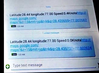
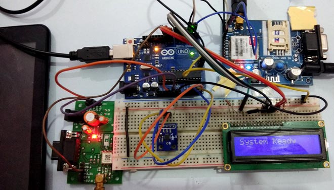
In our previous tutorials, we have learned about How to interface GPS module with Computer, how to build a Arduino GPS Clock and how to Track vehicle using GSM and GPS. Here in this project, we are going to build a Arduino based vehicle accident alert system using GPS, GSM and accelerometer. Accelerometer detects the sudden change in the axes of vehicle and GSM module sends the alert message on your Mobile Phone with the location of the accident. Location of accident is sent in the form of Google Map link, derived from the latitude and longitude from GPS module. The Message also contains the speed of vehicle in knots. See the Demo Video at the end. This Vehicle Accident alert project can also be used as a Tracking System and much more, by just making few changes in hardware and software.
Components Required:
- Arduino Uno
- GSM Module (SIM900A)
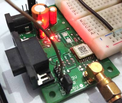
- GPS Module (SIM28ML)
- Accelerometer (ADXL335)
- 16x2 LCD
- Power Supply
- Connecting Wires
- 10 K-POT
- Breadboard or PCB
- Power supply 12v 1amp
Before going into Project, we will discuss about GPS, GSM and Accelerometer.
GPS Module and Its Working:
GPS stands for Global Positioning System and used to detect the Latitude and Longitude of any location on the Earth, with exact UTC time (Universal Time Coordinated). GPS module is used to track the location of accident in our project. This device receives the coordinates from the satellite for each and every second, with time and date. We have previously extracted $GPGGA string in Vehicle Tracking System to find the Latitude and Longitude Coordinates.
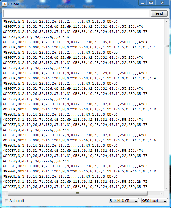
GPS module sends the data related to tracking position in real time, and it sends so many data in NMEA format (see the screenshot below). NMEA format consists several sentences, in which we only need one sentence. This sentence starts from $GPGGA and contains the coordinates, time and other useful information. This GPGGA is referred to Global Positioning System Fix Data. Know more about NMEA sentences and reading GPS data here.
We can extract coordinate from $GPGGA string by counting the commas in the string. Suppose you find $GPGGA string and stores it in an array, then Latitude can be found after two commas and Longitude can be found after four commas. Now, this latitude and longitude can be put in other arrays.
Below is the $GPGGA String, along with its description:
$GPGGA,104534.000,7791.0381,N,06727.4434,E,1,08,0.9,510.4,M,43.9,M,,*47
$GPGGA,HHMMSS.SSS,latitude,N,longitude,E,FQ,NOS,HDP,altitude,M,height,M,,checksum data
|
Identifier |
Description |
|
$GPGGA |
Global Positioning system fix data |
|
HHMMSS.SSS |
Time in hour minute seconds and milliseconds format. |
|
Latitude |
Latitude (Coordinate) |
|
N |
Direction N=North, S=South |
|
Longitude |
Longitude(Coordinate) |
|
E |
Direction E= East, W=West |
|
FQ |
Fix Quality Data |
|
NOS |
No. of Satellites being Used |
|
HDP |
Horizontal Dilution of Precision |
|
Altitude |
Altitude (meters above from sea level) |
|
M |
Meter |
|
Height |
Height |
|
Checksum |
Checksum Data |
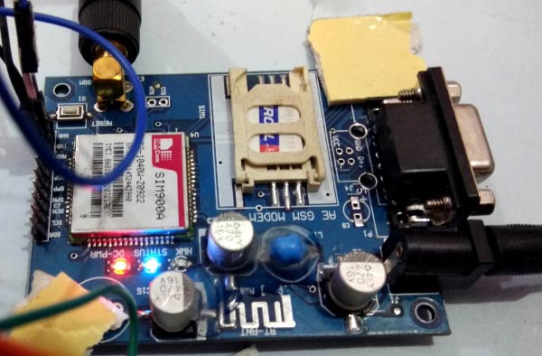
GSM Module:
The SIM900 is a complete Quad-band GSM/GPRS Module which can be embedded easily used by customer or hobbyist. SIM900 GSM Module provides an industry-standard interface. SIM900 delivers GSM/GPRS 850/900/1800/1900MHz performance for voice, SMS, Data with low power consumption. It is easily available in the market.
- SIM900 designed by using single-chip processor integrating AMR926EJ-S core
- Quad - band GSM/GPRS module in small size.
- GPRS Enabled
AT Command:
AT means ATTENTION. This command is used to control GSM module. There are some commands for calling and messaging that we have used in many of our previous GSM projects with Arduino. For testing GSM Module we used AT command. After receiving AT Command GSM Module respond with OK. It means GSM module is working fine. Below is some AT commands we used here in this project:
ATE0 For echo off
AT+CNMI=2,2,0,0,0  <ENTER>       Auto opened message Receiving.  (No need to open message)
ATD<Mobile Number>; <ENTER>      making a call (ATD+919610126059;\r\n)
AT+CMGF=1 <ENTER>                Selecting Text mode
AT+CMGS=”Mobile Number” <ENTER>  Assigning recipient’s mobile number
>>Now we can write our message
>>After writing message
Ctrl+Z  send message command (26 in decimal).
ENTER=0x0d in HEX
(To learn more about GSM module, Check our various GSM projects with various microcontrollers here)

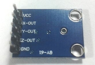
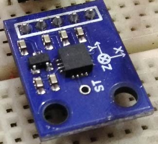
Accelerometer:
Pin Description of accelerometer:
- Vcc 5 volt supply should connect at this pin.
- X-OUT This pin gives an Analog output in x direction
- Y-OUT This pin give an Analog Output in y direction
- Z-OUT This pin gives an Analog Output in z direction
- GND Ground
- ST This pin used for set sensitivity of sensor
Also check our other projects using Accelerometer: Ping Pong Game using Arduino and Accelerometer Based Hand Gesture Controlled Robot.
Circuit Explanation:
Circuit Connections of this Vehicle Accident Alert System Project is simple. Here Tx pin of GPS module is directly connected to digital pin number 10 of Arduino. By using Software Serial Library here, we have allowed serial communication on pin 10 and 11, and made them Rx and Tx respectively and left the Rx pin of GPS Module open. By default Pin 0 and 1 of Arduino are used for serial communication but by using the SoftwareSerial library, we can allow serial communication on other digital pins of the Arduino. 12 Volt supply is used to power the GPS Module.
GSM module’s Tx and Rx pins of are directly connected to pin D2 and D3 of Arduino. For GSM interfacing, here we have also used software serial library. GSM module is also powered by 12v supply. An optional LCD’s data pins D4, D5, D6, and D7 are connected to pin number 6, 7, 8, and 9 of Arduino. Command pin RS and EN of LCD are connected with pin number 4 and 5 of Arduino and RW pin is directly connected with ground. A Potentiometer is also used for setting contrast or brightness of LCD.
An Accelerometer is added in this system for detecting an accident and its x,y, and z-axis ADC output pins are directly connected to Arduino ADC pin A1, A2, and A3.

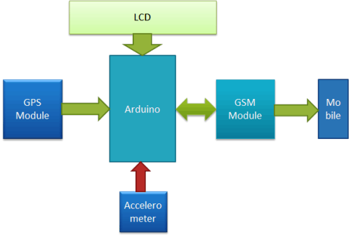
Working Explanation:
In this project, Arduino is used for controlling whole the process with a GPS Receiver and GSM module. GPS Receiver is used for detecting coordinates of the vehicle, GSM module is used for sending the alert SMS with the coordinates and the link to Google Map. Accelerometer namely ADXL335 is used for detecting accident or sudden change in any axis. And an optional 16x2 LCD is also used for displaying status messages or coordinates. We have used GPS Module SIM28ML and GSM Module SIM900A.
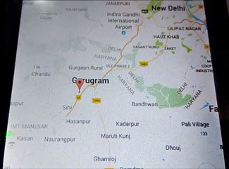
When we are ready with our hardware after programming, we can install it in our vehicle and power it up. Now whenever there is an accident, the car gets tilt and accelerometer changes his axis values. These values read by Arduino and checks if any change occurs in any axis. If any change occurs then Arduino reads coordinates by extracting $GPGGA String from GPS module data (GPS working explained above) and send SMS to the predefined number to the police or ambulance or family member with the location coordinates of accident place. The message also contains a Google Map link to the accident location, so that location can be easily tracked. When we receive the message then we only need to click the link and we will redirect to the Google map and then we can see the exact location of the vehicle. Speed of Vehicle, in knots (1.852 KPH), is also sent in the SMS and displayed on the LCD panel. Check the full Demo Video below the Project.
Here in this project, we can set the sensitivity of Accelerometer by putting min and max value in the code.
Here in the demo have used given values:
#define minVal -50
#define MaxVal 50
But for better results you can use 200 in place of 50, or can set according to your requirement.
Programming Explanation:
Complete Program has been given below in Code section; here we are explaining its various functions in brief.
First we have included all the required libraries or headers files and declared various variables for calculations and storing data temporary.
After this, we have created a function void initModule(String cmd, char *res, int t) to initialize the GSM module and checking its response using AT commands.
void initModule(String cmd, char *res, int t)
{
  while(1)
  {
    Serial.println(cmd);
    Serial1.println(cmd);
    delay(100);
    while(Serial1.available()>0)
    {
       if(Serial1.find(res))
       {
        Serial.println(res);
        delay(t);
        return;
       }

       else
       {
        Serial.println("Error");
       }
    }
    delay(t);
  }
}
After this, in void setup() function, we have initialized hardware and software serial communication, LCD, GPS, GSM module and accelerometer.
void setup()
{
  Serial1.begin(9600);
  Serial.begin(9600);
  lcd.begin(16,2);
  lcd.print("Accident Alert  ");
  lcd.setCursor(0,1);
  lcd.print("     System     ");
  delay(2000);
  lcd.clear();
  .... ......
  ...... .....
Accelerometer calibration process is also done in setup loop. In this, we have taken some samples and then find the average values for the x-axis, y-axis, and z-axis. And store them in a variable. Then we have used these sample values to read changes in accelerometer axis when vehicle gets tilt (accident).
  lcd.print("Callibrating ");
  lcd.setCursor(0,1);
  lcd.print("Acceleromiter");
  for(int i=0;i<samples;i++)
  {
    xsample+=analogRead(x);
    ysample+=analogRead(y);
    zsample+=analogRead(z);
  }

  xsample/=samples;
  ysample/=samples;
  zsample/=samples;

  Serial.println(xsample);
  Serial.println(ysample);
  Serial.println(zsample);
After this, in the void loop() function, we have read accelerometer axis values and done a calculation to extract changes with the help of samples that are taken in Calibration. Now if any changes are more or less then defined level then Arduino sends a message to the predefined number.
void loop()
{
    int value1=analogRead(x);
    int value2=analogRead(y);
    int value3=analogRead(z);

    int xValue=xsample-value1;
    int yValue=ysample-value2;
    int zValue=zsample-value3;

    Serial.print("x=");
    Serial.println(xValue);
    Serial.print("y=");
    Serial.println(yValue);
    Serial.print("z=");
    Serial.println(zValue);
    ..... .....
    ........ ...
Here we have also created some other function for various puposes like void gpsEvent() to get GPS coordinates, void coordinate2dec() for extracting coordinates from the GPS string and convert them into Decimal values, void show_coordinate() for displaying values over serial monitor and LCD, and finally the void Send() for sending alert SMS to the predefined number.
Complete code and demo video is given below, you can check all the functions in the code.
Complete Project Code
#include<SoftwareSerial.h>

SoftwareSerial Serial1(2,3); //make RX arduino line is pin 2, make TX arduino line is pin 3.

SoftwareSerial gps(10,11);

#include<LiquidCrystal.h>

LiquidCrystal lcd(4,5,6,7,8,9);
#define x A1

#define y A2

#define z A3
int xsample=0;

int ysample=0;

int zsample=0;
#define samples 10
#define minVal -50

#define MaxVal 50
int i=0,k=0;

int  gps_status=0;

float latitude=0;

float logitude=0;

String Speed="";

String gpsString="";

char *test="$GPRMC";
void initModule(String cmd, char *res, int t)

{

  while(1)

  {

    Serial.println(cmd);

    Serial1.println(cmd);

    delay(100);

    while(Serial1.available()>0)

    {

       if(Serial1.find(res))

       {

        Serial.println(res);

        delay(t);

        return;

       }
       else

       {

        Serial.println("Error");

       }

    }

    delay(t);

  }

}

void setup()

{

  Serial1.begin(9600);

  Serial.begin(9600);

  lcd.begin(16,2);

  lcd.print("Accident Alert  ");

  lcd.setCursor(0,1);

  lcd.print("     System     ");

  delay(2000);

  lcd.clear();

  lcd.print("Initializing");

  lcd.setCursor(0,1);

  lcd.print("Please Wait...");

  delay(1000);


  Serial.println("Initializing....");

  initModule("AT","OK",1000);

  initModule("ATE1","OK",1000);

  initModule("AT+CPIN?","READY",1000);

  initModule("AT+CMGF=1","OK",1000);

  initModule("AT+CNMI=2,2,0,0,0","OK",1000);

  Serial.println("Initialized Successfully");

  lcd.clear();

  lcd.print("Initialized");

  lcd.setCursor(0,1);

  lcd.print("Successfully");

  delay(2000);

  lcd.clear();

  lcd.print("Callibrating ");

  lcd.setCursor(0,1);

  lcd.print("Acceleromiter");

  for(int i=0;i<samples;i++)

  {

    xsample+=analogRead(x);

    ysample+=analogRead(y);

    zsample+=analogRead(z);

  }
  xsample/=samples;

  ysample/=samples;

  zsample/=samples;
  Serial.println(xsample);

  Serial.println(ysample);

  Serial.println(zsample);

  delay(1000);


  lcd.clear();

  lcd.print("Waiting For GPS");

  lcd.setCursor(0,1);

  lcd.print("     Signal    ");

  delay(2000);

  gps.begin(9600);

  get_gps();

  show_coordinate();

  delay(2000);

  lcd.clear();

  lcd.print("GPS is Ready");

  delay(1000);

  lcd.clear();

  lcd.print("System Ready");

  Serial.println("System Ready..");

}
void loop()

{

    int value1=analogRead(x);

    int value2=analogRead(y);

    int value3=analogRead(z);
    int xValue=xsample-value1;

    int yValue=ysample-value2;

    int zValue=zsample-value3;


    Serial.print("x=");

    Serial.println(xValue);

    Serial.print("y=");

    Serial.println(yValue);

    Serial.print("z=");

    Serial.println(zValue);
    if(xValue < minVal || xValue > MaxVal  || yValue < minVal || yValue > MaxVal  || zValue < minVal || zValue > MaxVal)

    {

      get_gps();

      show_coordinate();

      lcd.clear();

      lcd.print("Sending SMS ");

      Serial.println("Sending SMS");

      Send();

      Serial.println("SMS Sent");

      delay(2000);

      lcd.clear();

      lcd.print("System Ready");

    }

}
void gpsEvent()

{

  gpsString="";

  while(1)

  {

   while (gps.available()>0)            //Serial incoming data from GPS

   {

    char inChar = (char)gps.read();

     gpsString+= inChar;                    //store incoming data from GPS to temparary string str[]

     i++;

    // Serial.print(inChar);

     if (i < 7)

     {

      if(gpsString[i-1] != test[i-1])         //check for right string

      {

        i=0;

        gpsString="";

      }

     }

    if(inChar=='\r')

    {

     if(i>60)

     {

       gps_status=1;

       break;

     }

     else

     {

       i=0;

     }

    }

  }

   if(gps_status)

    break;

  }

}
void get_gps()

{

  lcd.clear();

  lcd.print("Getting GPS Data");

  lcd.setCursor(0,1);

  lcd.print("Please Wait.....");

   gps_status=0;

   int x=0;

   while(gps_status==0)

   {

    gpsEvent();

    int str_lenth=i;

    coordinate2dec();

    i=0;x=0;

    str_lenth=0;

   }

}
void show_coordinate()

{

    lcd.clear();

    lcd.print("Lat:");

    lcd.print(latitude);

    lcd.setCursor(0,1);

    lcd.print("Log:");

    lcd.print(logitude);

    Serial.print("Latitude:");

    Serial.println(latitude);

    Serial.print("Longitude:");

    Serial.println(logitude);

    Serial.print("Speed(in knots)=");

    Serial.println(Speed);

    delay(2000);

    lcd.clear();

    lcd.print("Speed(Knots):");

    lcd.setCursor(0,1);

    lcd.print(Speed);

}
void coordinate2dec()

{

  String lat_degree="";

    for(i=20;i<=21;i++)

      lat_degree+=gpsString[i];


  String lat_minut="";

     for(i=22;i<=28;i++)

      lat_minut+=gpsString[i];
  String log_degree="";

    for(i=32;i<=34;i++)

      log_degree+=gpsString[i];
  String log_minut="";

    for(i=35;i<=41;i++)

      log_minut+=gpsString[i];


    Speed="";

    for(i=45;i<48;i++)          //extract longitude from string

      Speed+=gpsString[i];


     float minut= lat_minut.toFloat();

     minut=minut/60;

     float degree=lat_degree.toFloat();

     latitude=degree+minut;


     minut= log_minut.toFloat();

     minut=minut/60;

     degree=log_degree.toFloat();

     logitude=degree+minut;

}
void Send()

{

   Serial1.println("AT");

   delay(500);

   serialPrint();

   Serial1.println("AT+CMGF=1");

   delay(500);

   serialPrint();

   Serial1.print("AT+CMGS=");

   Serial1.print('"');

   Serial1.print("9821757249");    //mobile no. for SMS alert

   Serial1.println('"');

   delay(500);

   serialPrint();

   Serial1.print("Latitude:");

   Serial1.println(latitude);

   delay(500);

   serialPrint();

   Serial1.print(" longitude:");

   Serial1.println(logitude);

   delay(500);

   serialPrint();

   Serial1.print(" Speed:");

   Serial1.print(Speed);

   Serial1.println("Knots");

   delay(500);

   serialPrint();

   Serial1.print("http://maps.google.com/maps?&z=15&mrt=yp&t=k&q=");

   Serial1.print(latitude,6);

   Serial1.print("+");              //28.612953, 77.231545   //28.612953,77.2293563

   Serial1.print(logitude,6);

   Serial1.write(26);

   delay(2000);

   serialPrint();

}
void serialPrint()

{

  while(Serial1.available()>0)

  {

    Serial.print(Serial1.read());

  }

}
Comments
Can this sensors produced
Can this sensors produced output at the same time? when every sensor/module detect something at same time?
Connecting 2 accelerometers
I want to connect 2 accelerometer in the above program
Kindly please help mee
As soon as possible
SIM800 and GPS6MV2
Is it possible to replace SIM900 with SIM800 and the GPS module SIM28ML with GPS6MV2? I hope you can answer this question. Thank you
Yes you can. Just replace the
Yes you can. Just replace the AT commands with the at commands for the new module. I replace both with SIM808. Which has GPS+GSM in one module.
complete project with SIM808.
Good day
can you please email me the complete project of this project with SIM808 and also the code.
Thank you.
Hi! Good day
Can you please e-mail me the complete project of this project with SIM808 and also the code.
It will be a really great help.
Thank you.
can you please send the code
can you please send the code for sim808 module
pls can you send me the
pls can you send me the project commad using sim808 i want to do the project but has no idea where to start fom can you be of help . pls send to my email
I think speed drived by this
I think speed drived by this code is wrong you need to use $GPRMC line for that
Accident reporting using gsm,gps
Hai bro,please help me for doing this project...... please send me the code and circuit diagram for the above project .....I had tried the above code several times but it is not showing the output....please help me,,,....it means a lot
can i use a7 gps module
can i use a7 gps module instead of SIM28ML
error in the code
While compiling and the code there is some error called (redefinition of 'SoftwareSerial gps').How to recover it.Please help me......
can we use GPS SIM6MV2
can we use GPS SIM6MV2 instead of sim28ml?
does this project fall under
does this project fall under the category of IOT? what is the iot componenet in this project
YES IT MAY COME UNDER IOT
Since, the signals are sending the information to cloud by that only you are receiving, messages, and also your signal is being on syncing with the cloud. So it may come under IOT. By sitting in home it self you are getting to know how the things may happened.
hello saddam, can I get the
hello saddam, can I get the full report for this project?
dear sir i
dear sir i
I want to put a push button to send "lat" and "long" to a mobile number
can you please how how to modify the code
thanks
computer engineering
I am doing my final project on this title please help me. the given code has some error that says char to string problem and also how I get the accelerometer liberary for proteus please help me
Can we use s1216f8 GPS
Can we use s1216f8 GPS instead of gps sim 28ml
Regarding to use gps S1216F8
Can we use S1216F8gps instead of gps 28 ml
please help me when I excute the code above it shows those error
C:\Users\Habtamu\Desktop\error\error.ino:26:12: warning: deprecated conversion from string constant to 'char*' [-Wwrite-strings]
char *test="$GPRMC";
^
C:\Users\Habtamu\Desktop\error\error.ino: In function 'void setup()':
C:\Users\Habtamu\Desktop\error\error.ino:69:28: warning: deprecated conversion from string constant to 'char*' [-Wwrite-strings]
initModule("AT","OK",1000);
^
C:\Users\Habtamu\Desktop\error\error.ino:70:30: warning: deprecated conversion from string constant to 'char*' [-Wwrite-strings]
initModule("ATE1","OK",1000);
^
C:\Users\Habtamu\Desktop\error\error.ino:71:37: warning: deprecated conversion from string constant to 'char*' [-Wwrite-strings]
initModule("AT+CPIN?","READY",1000);
^
C:\Users\Habtamu\Desktop\error\error.ino:72:35: warning: deprecated conversion from string constant to 'char*' [-Wwrite-strings]
initModule("AT+CMGF=1","OK",1000);
^
C:\Users\Habtamu\Desktop\error\error.ino:73:43: warning: deprecated conversion from string constant to 'char*' [-Wwrite-strings]
initModule("AT+CNMI=2,2,0,0,0","OK",1000);
^
Sketch uses 12180 bytes (37%) of program storage space. Maximum is 32256 bytes.
Global variables use 961 bytes (46%) of dynamic memory, leaving 1087 bytes for local variables. Maximum is 2048 bytes.
Hello sir, have you solve
Hello sir, have you solve this problem? I also have the same problem.
when i compile the code in
when i compile the code in arduino sketch it says .
C:\Users\foxcent12\Desktop\VEHICLE_ACCIDENT_ALERT\VEHICLE_ACCIDENT_ALERT.ino:26:12: warning: deprecated conversion from string constant to 'char*' [-Wwrite-strings]
char *test="$GPRMC";
^
C:\Users\foxcent12\Desktop\VEHICLE_ACCIDENT_ALERT\VEHICLE_ACCIDENT_ALERT.ino: In function 'void setup()':
C:\Users\foxcent12\Desktop\VEHICLE_ACCIDENT_ALERT\VEHICLE_ACCIDENT_ALERT.ino:69:28: warning: deprecated conversion from string constant to 'char*' [-Wwrite-strings]
initModule("AT","OK",1000);
^
C:\Users\foxcent12\Desktop\VEHICLE_ACCIDENT_ALERT\VEHICLE_ACCIDENT_ALERT.ino:70:30: warning: deprecated conversion from string constant to 'char*' [-Wwrite-strings]
initModule("ATE1","OK",1000);
^
C:\Users\foxcent12\Desktop\VEHICLE_ACCIDENT_ALERT\VEHICLE_ACCIDENT_ALERT.ino:71:37: warning: deprecated conversion from string constant to 'char*' [-Wwrite-strings]
initModule("AT+CPIN?","READY",1000);
^
C:\Users\foxcent12\Desktop\VEHICLE_ACCIDENT_ALERT\VEHICLE_ACCIDENT_ALERT.ino:72:35: warning: deprecated conversion from string constant to 'char*' [-Wwrite-strings]
initModule("AT+CMGF=1","OK",1000);
^
C:\Users\foxcent12\Desktop\VEHICLE_ACCIDENT_ALERT\VEHICLE_ACCIDENT_ALERT.ino:73:43: warning: deprecated conversion from string constant to 'char*' [-Wwrite-strings]
initModule("AT+CNMI=2,2,0,0,0","OK",1000);
^
Sketch uses 12232 bytes (37%) of program storage space. Maximum is 32256 bytes.
Global variables use 975 bytes (47%) of dynamic memory, leaving 1073 bytes for local variables. Maximum is 2048 bytes.
Sir can i replace SIM900,
Sir can i replace SIM900, ADXL335 and SIM28ML to SIM800L, ADXL 355 and GPS6MV2?
is there any changing in code sir ? thankkss
You can replace but code will
You can replace but code will change
Sir what specifically code
Sir what specifically code that i will change ? thankkk yoouu for the response sir. appreciate it :)
Sir what specifically part of
Sir what specifically part of the code i change sir ? thanksss
I have replaced accelerometer
I have replaced accelerometer from ADXL335 to MPU6050, and GPS SIM28ml to NEO6MV2, what will change in the program? please help me
Sri can you show me how to
Sri can you show me how to connect a button to the circuuit to send the data
love to hear from you soon ...
Modification of the System
If I needed to integrate a manual trigger to the system that prompts the system to send an sms with the location irregardless of an accident occurence or not, how would i do that?
REQUEST FOR GPS CODE ONLY
sir i am in arduino related work all in need a simple gps code which only print the latitude and longitude on serial monitor please help me please
code1:252: error: 'class
code1:252: error: 'class String' has no member named 'toFloat'
i got stuck with this error..can u help me out???
hi, i would like to send the
hi, i would like to send the data into my own local server instead of send the data thru gsm to mobile. how can i doi it?
about the working of this project
can you plzz send the correct code and connection diagram because I have tried the code u gave but it does not work.
I'd like to buy this system
Hello Saddam, I'd really love to get in touch with you, I'd like to get me this system. Please say something
CODIGO COMPLETO
Buenas tardes serian tan amables de facilitarme el codigo correcto porfa, es para mi proyecto de una materia y lo necesito podrian enviarmelo a mi correo madelyne-theprincess15@hotmail.com
error in the code
hello sir, there is an error in this code. Can u plz send me the modified code. It's very important sir..plz respond
When you can spot the error,
When you can spot the error, why not just correct it
two problems
first i would ike to thank you for this awesome project.
however, iam uesing tinygps neo-6m-0-001 and for some resone it gives wrong latitude but the longitude is correct which lead to very wrong locattion like in another counrtry .
also after "GPS READY" it stuck in no ending lop of sending the lcation and resend over and over even if the /adxl335 is not connected.
note that iam uesng SIM900 insted of SIM900A
About the sim
We will place a sim card in the gsm...and what about the balance in the sim card...should we recharge the sim card or no need could you please help me out..?
Is it possible to replace gsm
Is it possible to replace gsm sim900 with gsm sim 800.If yes,is there in any change in code.Please reply me soooon..waiting for ur response.
help
C:\Users\harsh\AppData\Local\Temp\Temp1_accident_alert_system.zip\accident_alert_system\accident_alert_system.ino:21:12: warning: ISO C++ forbids converting a string constant to 'char*' [-Wwrite-strings]
char *test="$GPRMC";
^
C:\Users\harsh\AppData\Local\Temp\Temp1_accident_alert_system.zip\accident_alert_system\accident_alert_system.ino: In function 'void setup()':
C:\Users\harsh\AppData\Local\Temp\Temp1_accident_alert_system.zip\accident_alert_system\accident_alert_system.ino:61:28: warning: ISO C++ forbids converting a string constant to 'char*' [-Wwrite-strings]
initModule("at","OK",1000);
^
C:\Users\harsh\AppData\Local\Temp\Temp1_accident_alert_system.zip\accident_alert_system\accident_alert_system.ino:62:30: warning: ISO C++ forbids converting a string constant to 'char*' [-Wwrite-strings]
initModule("ATE1","OK",1000);
^
C:\Users\harsh\AppData\Local\Temp\Temp1_accident_alert_system.zip\accident_alert_system\accident_alert_system.ino:63:37: warning: ISO C++ forbids converting a string constant to 'char*' [-Wwrite-strings]
initModule("at+CPIN?","READY",1000);
^
C:\Users\harsh\AppData\Local\Temp\Temp1_accident_alert_system.zip\accident_alert_system\accident_alert_system.ino:64:35: warning: ISO C++ forbids converting a string constant to 'char*' [-Wwrite-strings]
initModule("at+CMGF=1","OK",1000);
^
C:\Users\harsh\AppData\Local\Temp\Temp1_accident_alert_system.zip\accident_alert_system\accident_alert_system.ino:65:43: warning: ISO C++ forbids converting a string constant to 'char*' [-Wwrite-strings]
initModule("at+CNMI=2,2,0,0,0","OK",1000);
^
Sketch uses 12084 bytes (37%) of program storage space. Maximum is 32256 bytes.
Global variables use 945 bytes (46%) of dynamic memory, leaving 1103 bytes for local variables. Maximum is 2048 bytes.
Hi! can I ask if this code
Hi! can I ask if this code has an equivalent with MikroC using PIC18F4550?
hello sir, i can't find GPS
hello sir, i can't find GPS Module (SIM28ML) near malaysia, if i use other gps is it compatible? hope you can help me...if i used USB GPS Tracking Ublox NEO-7N Module , Positioning Coordinate Arduino can?
can anyone edit the program
can anyone edit the program for gps-neo 6m and gsm800l please it is for my thesis so i can graduate
mam can u please send the
mam can u please send the correct code and circuit diagram i need it for my final year project
hi bro, can I ask what
hi bro, can I ask what library do you use to run this code?
thank you reply ASAP
Solved The Error in this…
Solved The Error in this code
Here is the solved code:
#include<SoftwareSerial.h>
SoftwareSerial Serial1(2,3); //make RX arduino line is pin 2, make TX arduino line is pin 3.
SoftwareSerial gps(10,11);
#include<LiquidCrystal.h>
LiquidCrystal lcd(4,5,6,7,8,9);
#define x A1
#define y A2
#define z A3
int xsample=0;
int ysample=0;
int zsample=0;
#define samples 10
#define minVal -50
#define MaxVal 50
int i=0,k=0;
int gps_status=0;
float latitude=0;
float logitude=0;
String Speed="";
String gpsString="";
const char *test="$GPRMC";
void initModule(String cmd, const char *res, int t)
{
while(1)
{
Serial.println(cmd);
Serial1.println(cmd);
delay(100);
while(Serial1.available()>0)
{
if(Serial1.find(*res))
{
Serial.println(*res);
delay(t);
return;
}
else
{
Serial.println("Error");
}
}
delay(t);
}
}
void setup()
{
Serial1.begin(9600);
Serial.begin(9600);
lcd.begin(16,2);
lcd.print("Accident Alert ");
lcd.setCursor(0,1);
lcd.print(" System ");
delay(2000);
lcd.clear();
lcd.print("Initializing");
lcd.setCursor(0,1);
lcd.print("Please Wait...");
delay(1000);
Serial.println("Initializing....");
initModule("AT","OK",1000);
initModule("ATE1","OK",1000);
initModule("AT+CPIN?","READY",1000);
initModule("AT+CMGF=1","OK",1000);
initModule("AT+CNMI=2,2,0,0,0","OK",1000);
Serial.println("Initialized Successfully");
lcd.clear();
lcd.print("Initialized");
lcd.setCursor(0,1);
lcd.print("Successfully");
delay(2000);
lcd.clear();
lcd.print("Callibrating ");
lcd.setCursor(0,1);
lcd.print("Acceleromiter");
for(int i=0;i<samples;i++)
{
xsample+=analogRead(x);
ysample+=analogRead(y);
zsample+=analogRead(z);
}
xsample/=samples;
ysample/=samples;
zsample/=samples;
Serial.println(xsample);
Serial.println(ysample);
Serial.println(zsample);
delay(1000);
lcd.clear();
lcd.print("Waiting For GPS");
lcd.setCursor(0,1);
lcd.print(" Signal ");
delay(2000);
gps.begin(9600);
get_gps();
show_coordinate();
delay(2000);
lcd.clear();
lcd.print("GPS is Ready");
delay(1000);
lcd.clear();
lcd.print("System Ready");
Serial.println("System Ready..");
}
void loop()
{
int value1=analogRead(x);
int value2=analogRead(y);
int value3=analogRead(z);
int xValue=xsample-value1;
int yValue=ysample-value2;
int zValue=zsample-value3;
Serial.print("x=");
Serial.println(xValue);
Serial.print("y=");
Serial.println(yValue);
Serial.print("z=");
Serial.println(zValue);
if(xValue < minVal || xValue > MaxVal || yValue < minVal || yValue > MaxVal || zValue < minVal || zValue > MaxVal)
{
get_gps();
show_coordinate();
lcd.clear();
lcd.print("Sending SMS ");
Serial.println("Sending SMS");
Send();
Serial.println("SMS Sent");
delay(2000);
lcd.clear();
lcd.print("System Ready");
}
}
void gpsEvent()
{
gpsString="";
while(1)
{
while (gps.available()>0) //Serial incoming data from GPS
{
char inChar = (char)gps.read();
gpsString+= inChar; //store incoming data from GPS to temparary string str[]
i++;
// Serial.print(inChar);
if (i < 7)
{
if(gpsString[i-1] != test[i-1]) //check for right string
{
i=0;
gpsString="";
}
}
if(inChar=='\r')
{
if(i>60)
{
gps_status=1;
break;
}
else
{
i=0;
}
}
}
if(gps_status)
break;
}
}
void get_gps()
{
lcd.clear();
lcd.print("Getting GPS Data");
lcd.setCursor(0,1);
lcd.print("Please Wait.....");
gps_status=0;
int x=0;
while(gps_status==0)
{
gpsEvent();
int str_lenth=i;
coordinate2dec();
i=0;x=0;
str_lenth=0;
}
}
void show_coordinate()
{
lcd.clear();
lcd.print("Lat:");
lcd.print(latitude);
lcd.setCursor(0,1);
lcd.print("Log:");
lcd.print(logitude);
Serial.print("Latitude:");
Serial.println(latitude);
Serial.print("Longitude:");
Serial.println(logitude);
Serial.print("Speed(in knots)=");
Serial.println(Speed);
delay(2000);
lcd.clear();
lcd.print("Speed(Knots):");
lcd.setCursor(0,1);
lcd.print(Speed);
}
void coordinate2dec()
{
String lat_degree="";
for(i=20;i<=21;i++)
lat_degree+=gpsString[i];
String lat_minut="";
for(i=22;i<=28;i++)
lat_minut+=gpsString[i];
String log_degree="";
for(i=32;i<=34;i++)
log_degree+=gpsString[i];
String log_minut="";
for(i=35;i<=41;i++)
log_minut+=gpsString[i];
Speed="";
for(i=45;i<48;i++) //extract longitude from string
Speed+=gpsString[i];
float minut= lat_minut.toFloat();
minut=minut/60;
float degree=lat_degree.toFloat();
latitude=degree+minut;
minut= log_minut.toFloat();
minut=minut/60;
degree=log_degree.toFloat();
logitude=degree+minut;
}
void Send()
{
Serial1.println("AT");
delay(500);
serialPrint();
Serial1.println("AT+CMGF=1");
delay(500);
serialPrint();
Serial1.print("AT+CMGS=");
Serial1.print('"');
Serial1.print("01760789491"); //mobile no. for SMS alert
Serial1.println('"');
delay(500);
serialPrint();
Serial1.print("Latitude:");
Serial1.println(latitude);
delay(500);
serialPrint();
Serial1.print(" longitude:");
Serial1.println(logitude);
delay(500);
serialPrint();
Serial1.print(" Speed:");
Serial1.print(Speed);
Serial1.println("Knots");
delay(500);
serialPrint();
Serial1.print("http://maps.google.com/maps?&z=15&mrt=yp&t=k&q=");
Serial1.print(latitude,6);
Serial1.print("+"); //28.612953, 77.231545 //28.612953,77.2293563
Serial1.print(logitude,6);
Serial1.write(26);
delay(2000);
serialPrint();
}
void serialPrint()
{
while(Serial1.available()>0)
{
Serial.print(Serial1.read());
}
}

which aap is used for a skype drive robot please send me aap name?