

Welcome to another project in which we will build a small Robot which can walk and dance. The project aims in teaching you how to make small hobby robots using Arduino and how to program your Servo motors for such applications. At the end of the project you will be able to make this walking and dancing robot that takes command from an Android Mobile Phone to perform some pre-defined actions. You can also use the program (given at the end of the tutorial) to easily manipulate the actions of your very own robot by controlling the position of the servo motors using the Serial monitor. Having a 3d printer will make this project more interesting and look cool. But, if you do not have one you can use any of the online services or just use some cardboard to build the same.
Materials Required:
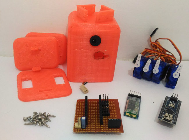
The following are the materials required for building this robot:
- Arduino nano
- Servo SG90 – 4Nos
- Male berg sticks
- HC-05/HC-06 Bluetooth module
- 3D printer
As you can see this 3D printed robot requires very minimal electronics parts to build to keep the cost of the project as low as possible. This project is only for conceptual and fun purpose and does not have any real time application so far.
3D printing the required parts:
3D printing is an amazing tool that can contribute a lot when building prototype projects or experimenting with new mechanical designs. If you have not yet discovered the benefits of a 3D printer or how it works you can read The beginners Guide to 3D printing .
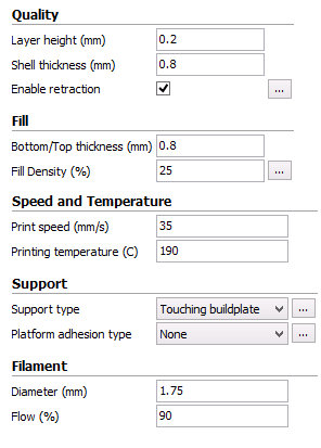
In this project the body of the Robot shown above is completely 3D printed. You can download the STL files from here. Load these files on your 3D printing software like Cura and directly print them. I have used a very basic printer of mine to print all the parts. The printer is FABX v1 from 3ding which comes at an affordable price with a print volume of 10 cubic cm. The cheap price comes with a trade off with low print resolution and no SD card or print resuming function. I am using software called Cura to print the STL files. The settings that I used to print the materials are given below you can use the same or change them based on your printer.
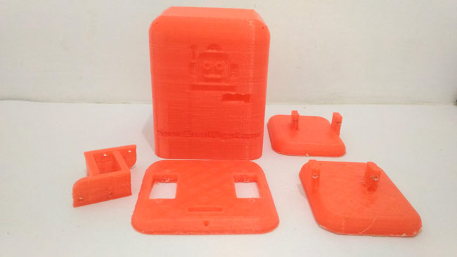
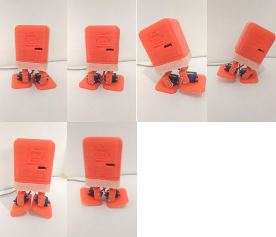
Once you print all the parts clean the supports (if any) and then make sure the holes on the leg and belly part are big enough to fit a screw. If not, use a needle to make the hole lightly bigger. Your 3D printed parts will look like something below.
Hardware and Schematics:
The Hardware for this Mobile Phone Controlled Biped Arduino Robot is really simple. The complete schematics is shown in the below image
 Robot Circuit Diagram")
I have used a Perf board to make the above connections. Make sure that your circuit will also fit inside the head of the robot. Once your Perf board is ready it should look something like below.
Assembling the robot:
Once the Hardware and the 3D printed parts are ready we can assemble the robot. Before fixing the motors make sure you place the motors in the below angles so that the program works flawlessly.
|
Motor Number |
Motor place |
Motor position |
|
1 |
Left Hip motor |
110 |
|
2 |
Right Hip motor |
100 |
|
4 |
Right Ankle Motor |
90 |
|
5 |
Right Hip motor |
80 |
These angles can be set by using the program given at the end of the tutorial. Simply upload the program to your Arduino after making the above connections and type in the following in the serial monitor (Note: Baud rate is 57600).
1, 100, 110
2,90,100
4,80,90
5,70,80
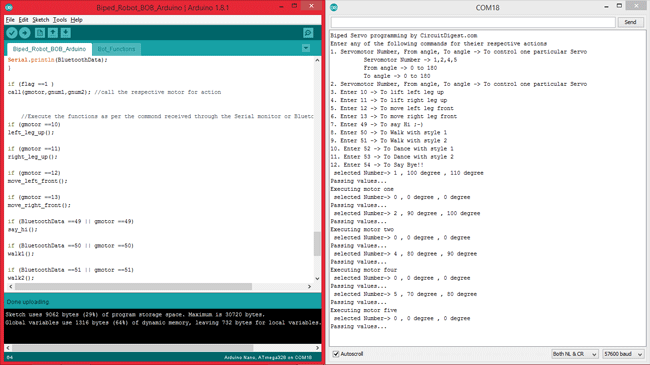
Your Serial monitor should look something like this after placing all your motors in position.
Once the motors are set in the corresponding angles mount them as shown in above figure.
If you are confused on how to assemble the motors follow the video at the end of this tutorial. Once the Robot is assembled it is time to program our dancing robot

Programming the Arduino for Biped Robot:
Programming the BBB Robot (Bluetooth Biped Bob) is the most interesting and fun part in this tutorial. If you are very good in programming servo motors with Arduino then I would recommend you to make your program. Bt, if you want learn how to use servo motors for robotic applications like this, then this program will be very helpful for. You can learn more about arduino programming in our arduino projects category.
The complete program is given at the end of this tutorial, or you can download the complete code from here. I will explain the segments of the same below. The program is capable of controlling the Robots actions through serial monitor or Bluetooth. You can also make your own moves by controlling every individual motor using the serial monitor.
   servo1.attach(3);
   servo2.attach(5);
   servo4.attach(9);
   servo5.attach(10);
The above lines of code it use to mention which servo motor is connected to which pin of the Arduino. Here in our case Servo 1,2,4 and 5 are connected to pins 3,5,9 and 10 respectively.
Bot_BT.begin(9600); //start the Bluetooth communication at 9600 baudrate

Serial.begin(57600);
As said earlier our walking robot can work on Bluetooth commands and also from commands from the serial monitor. Hence the Bluetooth serial communication works with a Baud Rate of 9600 and the serial communication works with Baud Rate of 57600. The name of our Bluetooth object here is “Bot_BT”.
switch (motor)
  {
    case 1:            // For motor one
      { Serial.println("Executing motor one");
        if(num1<num2) // Clock wise rotation
  { for ( pos =num1; pos<=num2; pos+=1)
  {
    servo1.write(pos);
    delay( 20);
  }}
if(num1>num2) // Anti-Clock wise rotation
  {
  for ( pos =num1; pos>=num2; pos-=1)
  {
    servo1.write(pos);
    delay( 20);
  }}
      break;
      }
       ////////JUST  DUPLICATE FOR OTHER SERVOS////
    case 2:    // For motor 2
      {
        Serial.println("Executing motor two");
        if(num1<num2)
  {
  for ( pos =num1; pos<=num2; pos+=1)
  {
    servo2.write(pos);
    delay( 20);
  }}
if(num1>num2)
  {
  for ( pos =num1; pos>=num2; pos-=1)
  {
    servo2.write(pos);
    delay( 20);
  }}
      break;
      }

    case 4:    // for motor four
      {
        Serial.println("Executing motor four");
        if(num1<num2)
  {
  for ( pos =num1; pos<=num2; pos+=1)
  {
    servo4.write(pos);
    delay (20);
  }}
if(num1>num2)
  {
  for ( pos =num1; pos>=num2; pos-=1)
  {
    servo4.write(pos);
    delay (20);
  }}
      break;
      }

      case 5:    // for motor five
      {
        Serial.println("Executing motor five");
  {
  for ( pos =num1; pos<=num2; pos+=1)
        if(num1<num2)
  {
    servo5.write(pos);
    delay (20);
  }}
if(num1>num2)
  {
  for ( pos =num1; pos>=num2; pos-=1)
  {
    servo5.write(pos);
    delay (20);
  }}
      break;
      }
The switch case shown above is used to control the servo motors individually. This will help in making your own creative moves with your robot. With this segment of code you can simply tell the motor number, from angle and to angle to make a particular motor move to a desired location.
For example if we want to move the motor number 1 which is the left hip motor from its default location of 110 degree to 60 degree. We can simply write “1,110,60” in the serial monitor of Arduino and hit enter. This will come in handy to make your own complex moves with your Robot. Once you experiment with all the from angel and to angle you can then make your own moves and repeat them by making it as a function.
 if(Serial.available()>0) //Read whats coming in through Serial
  {
  gmotor= Serial.parseInt();
  Serial.print(" selected Number-> ");
  Serial.print(gmotor);
  Serial.print(" , ");
  gnum1= Serial.parseInt();
  Serial.print(gnum1);
  Serial.print(" degree , ");
  gnum2= Serial.parseInt();
  Serial.print(gnum2);
  Serial.println(" degree ");
   flag=1;
   }
If a Serial data is available the number before the first “,” is considered as gmotor and then the number before the second “,” is considered as gnum1 and the number after the second “,” is considered as gnum2.
if (Bot_BT.available()) //Read whats coming in through Bluetooth
   {
BluetoothData=Bot_BT.read();
Serial.print("Incoming from BT:");
Serial.println(BluetoothData);
}
If the Bluetooth receives some information, the received information is stored in the variable “BluetoothData”. This variable is then compared to the pre-defined values to execute a particular action.
if (flag ==1 )
call(gmotor,gnum1,gnum2); //call the respective motor for action
    //Execute the functions as per the commond received through the Serial monitor or Bluetooth//
if (gmotor ==10)
left_leg_up();
if (gmotor ==11)
right_leg_up();
if (gmotor ==12)
move_left_front();
if (gmotor ==13)
move_right_front();
if (BluetoothData ==49 || gmotor ==49)
say_hi();
if (BluetoothData ==50 || gmotor ==50)
walk1();
if (BluetoothData ==51 || gmotor ==51)
walk2();
if (BluetoothData ==52 || gmotor ==52)
dance1();
if (BluetoothData ==53 || gmotor ==53)
dance2();
if (BluetoothData ==54 || gmotor ==54)
{test();test();test();}
This is where the functions are called based on the values received from the serial monitor or the Bluetooth. As shown above the variable gmotor will have the value of serial monitor and BluetoothData will have the value from Bluetooth device. The numbers 10,11,12 upto 53,54 are pre-defined numbers.
For example if you enter the number 49 in the serial monitor. The say_hi() function will be executed where the robot will wave you a hi.
All the functions are defined inside the page “Bot_Functions”. You can open it and see what actually happens inside each function. All these functions were created by experimenting th e from angel and to angel of every motor using the switch case explained above. If you have any doubt you can use the comment section to post them and I will be happy to help you out.
Processing based Android Application:
The Android application to control the Robot was build using the Processing Android mode. If you want to make some changes to the Application you can download the complete Processing program from here.
If you simply want to use the application you can download it from here as an APK file and directly install it on your mobile phone.
Note: Your Bluetooth module should be named HC-06 else the application will not be able to connect to your Bluetooth Module.
Once the application is installed, you can pair the Bluetooth module with your Phone and then launch the application. It should look something like this below.
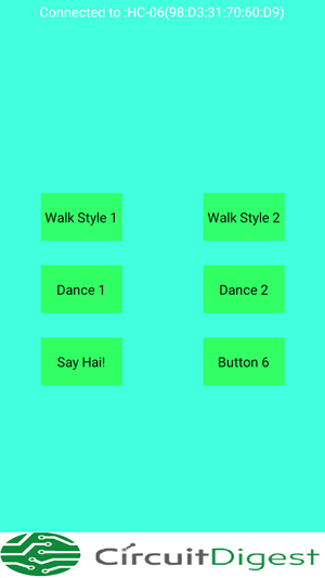
If you want to make your app more attractive or connect to any other device other than Hc-06. You can use the processing code and make some changes to it and then upload the code directly to your phone.
Working of Bluetooth Controlled Biped Robot:
Once your Hardware, Android Application and Arduino Sketch is ready it is time to have some fun with our robot. You can control the Robot from Bluetooth Application by using the buttons in the application or directly from Serial monitor by using as of the following commands as shown in the image below.
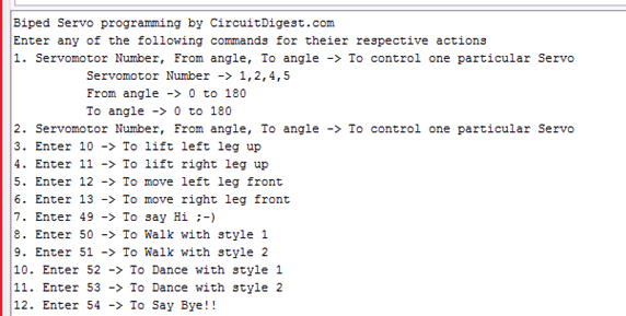
Each command will make the robot perform some peculiar tasks and you can also add on more actions based on your creativity.
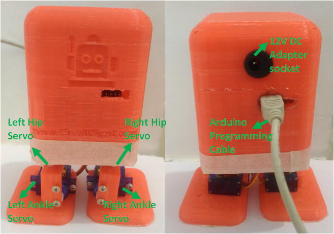
The Robot can also be powered by a 12V adapter or can also be powered by using a 9V battery. This battery can be easily positioned below the Perf board and can also be covered with the Head of the Robot.
The complete Working of this Smart Phone Controlled Robot can be found in the Video below.
Complete Project Code
/*Arduino Code for Walking and Dancing Robot

 * Coded by Circuitdigest.com

 * On 25-05-2017

 */
 /*CONNECTION DETIALS

  * Arduino D11 -> RX of BT Module

  * Arduino D12 -> Tx of BT

  * Arduino D2  -> Hall sensor 3rd pin

  * Servo1 -> pin 3 of arduino Nano

  * Servo2 -> pin 5 of arduino Nano

  * Servo4 -> pin 9 of arduino Nano

  * Servo5 -> pin 10 of arduino Nano

  */

#include <Servo.h> //header to srive servo motors

#include <SoftwareSerial.h>// import the serial library

SoftwareSerial Bot_BT(12, 11);  // RX, TX

int ledpin=13; // led on D13 will show blink on / off

int BluetoothData; // the data given from Computer
//lets declare the servo objects

Servo servo1;

Servo servo2;

Servo servo3;

Servo servo4;

Servo servo5;

//End of declaration
long gmotor,gnum1,gnum2;

int pos,pos2;

int flag=0;

int poss1,poss2,poss3,poss4;
void setup()

{

   servo1.attach(3);

   servo2.attach(5);;

   servo4.attach(9);

   servo5.attach(10);
   //**Initial position of all four servo motors**//

   servo1.write(110);

   servo2.write(100);

   servo4.write(90);

   servo5.write(80);

   //**inititialised**//


Bot_BT.begin(9600); //start the Bluetooth communication at 9600 baudrate

Bot_BT.println("Blue Bob is ready to take actions");
Serial.begin(57600);

Serial.println("Biped Servo programming by CircuitDigest.com");

Serial.println("Enter any of the following commands for theier respective actions");

Serial.println("1. Servomotor Number, From angle, To angle -> To control one particular Servo");

Serial.println("          Servomotor Number -> 1,2,4,5");

Serial.println("          From angle -> 0 to 180");

Serial.println("          To angle -> 0 to 180");

Serial.println("2. Servomotor Number, From angle, To angle -> To control one particular Servo");

Serial.println("3. Enter 10 -> To lift left leg up");

Serial.println("4. Enter 11 -> To lift right leg up");

Serial.println("5. Enter 12 -> To move left leg front");

Serial.println("6. Enter 13 -> To move right leg front");

Serial.println("7. Enter 49 -> To say Hi ;-)");

Serial.println("8. Enter 50 -> To Walk with style 1");

Serial.println("9. Enter 51 -> To Walk with style 2");

Serial.println("10. Enter 52 -> To Dance with style 1");

Serial.println("11. Enter 53 -> To Dance with style 2");

Serial.println("12. Enter 54 -> To Say Bye!!");

}

//***Function for each Servo actions**//

void call(int motor, int num1, int num2) // The values like Motor number , from angle and to angle are received

{

Serial.println("Passing values...");

flag =0;

switch (motor)

  {

    case 1:            // For motor one

      { Serial.println("Executing motor one");

        if(num1<num2) // Clock wise rotation

  { for ( pos =num1; pos<=num2; pos+=1)

  {

    servo1.write(pos);

    delay( 20);

  }}
if(num1>num2) // Anti-Clock wise rotation

  {

  for ( pos =num1; pos>=num2; pos-=1)

  {

    servo1.write(pos);

    delay( 20);

  }}

      break;

      }
       ////////JUST  DUPLICATE FOR OTHER SERVOS////


    case 2:    // For motor 2

      {

        Serial.println("Executing motor two");

        if(num1<num2)

  {

  for ( pos =num1; pos<=num2; pos+=1)

  {

    servo2.write(pos);

    delay( 20);

  }}

if(num1>num2)

  {

  for ( pos =num1; pos>=num2; pos-=1)

  {

    servo2.write(pos);

    delay( 20);

  }}

      break;

      }


    case 4:    // for motor four

      {

        Serial.println("Executing motor four");

        if(num1<num2)

  {

  for ( pos =num1; pos<=num2; pos+=1)

  {

    servo4.write(pos);

    delay (20);

  }}
if(num1>num2)

  {

  for ( pos =num1; pos>=num2; pos-=1)

  {

    servo4.write(pos);

    delay (20);

  }}

      break;

      }


      case 5:    // for motor five

      {

        Serial.println("Executing motor five");

  {

  for ( pos =num1; pos<=num2; pos+=1)

        if(num1<num2)

  {

    servo5.write(pos);

    delay (20);

  }}
if(num1>num2)

  {

  for ( pos =num1; pos>=num2; pos-=1)

  {

    servo5.write(pos);

    delay (20);

  }}

      break;

      }

  }

}

void loop()

{
  if(Serial.available()>0) //Read whats coming in through Serial

  {

  gmotor= Serial.parseInt();

  Serial.print(" selected Number-> ");

  Serial.print(gmotor);

  Serial.print(" , ");

  gnum1= Serial.parseInt();

  Serial.print(gnum1);

  Serial.print(" degree , ");

  gnum2= Serial.parseInt();

  Serial.print(gnum2);

  Serial.println(" degree ");

   flag=1;

   }
 if (Bot_BT.available()) //Read whats coming in through Bluetooth

   {

BluetoothData=Bot_BT.read();

Serial.print("Incoming from BT:");

Serial.println(BluetoothData);

}


if (flag ==1 )

call(gmotor,gnum1,gnum2); //call the respective motor for action


    //Execute the functions as per the commond received through the Serial monitor or Bluetooth//

if (gmotor ==10)

left_leg_up();
if (gmotor ==11)

right_leg_up();
if (gmotor ==12)

move_left_front();
if (gmotor ==13)

move_right_front();
if (BluetoothData ==49 || gmotor ==49)

say_hi();
if (BluetoothData ==50 || gmotor ==50)

walk1();
if (BluetoothData ==51 || gmotor ==51)

walk2();
if (BluetoothData ==52 || gmotor ==52)

dance1();
if (BluetoothData ==53 || gmotor ==53)

dance2();
if (BluetoothData ==54 || gmotor ==54)

{test();test();test();}
//End of executions//
gmotor=0; //To prevet repetetion

BluetoothData = 0; //To prevet repetetion

//stay_put(); //bring the Bot to initial posotion if required

}

/*---------------------------------------------------------------------------*/

// Code for Bot Functions......

//***Function to lift the left leg**//

void stay_put()

{

   servo5.attach(10);

   servo1.write(110);

   servo2.write(100);

   servo4.write(90);

   servo5.write(80);

   delay(20);

}

//**_____End of Function______**//

//***Function to lift the left lef**//

void left_leg_up()

{

   Serial.println("left leg up");

    poss1 = 80;

    poss2 = 110;

   do{

    servo5.write(poss1);

    servo4.write(poss2);

    poss1++;

    poss2++;

    delay(20);

   }while(poss1 <100 || poss2<140);

   call(4,130,100);

}

//**_____End of Function______**//

//***Function to lift the left lef**//

void right_leg_up()

{

Serial.println("right leg up");

    poss1 = 80;

    poss2 = 100;

   do{

    servo4.write(poss2);

    servo5.write(poss1);

    poss1--;

    poss2--;

    delay(20);

   }while(poss1 >50 || poss2>60);

   call(5,50,80);

}

//**_____End of Function______**//

//***Function to lift the left lef**//

void move_left_front()

{

   Serial.println("moving left front");

    poss1=120;poss2=110;poss3=110;

       do{

    servo2.write(poss1);

    servo1.write(poss2);

    servo5.write(poss3);

    poss1--;

    poss2--;

    poss3--;

    delay(20);

   }while(poss1 >100 || poss2>80 || poss3>80  );

}

//**_____End of Function______**//

//***Function to lift the left lef**//

void  move_right_front()

{

    poss1=80;poss2=100;poss3=60;

       do{

    servo1.write(poss1);

    servo2.write(poss2);

    servo4.write(poss3);

    poss1++;

    poss2++;

    poss3++;

    delay(20);

   }while(poss1 <110 || poss2<120 || poss3<90);

}

//**_____End of Function______**//

//***Function to lift the left lef**//

void say_hi()

{

  stay_put();

  right_leg_up();

  call(5,80,50); //wave up

  call(5,50,80); //wave down

  call(5,80,50); //wave up

  call(5,50,80); //wave down

  stay_put();

}

//**_____End of Function______**//

//***Function to lift the left lef**//

void walk1()

{

  stay_put();

  char temp=10; //number of steps to make * 2

  do{

  right_leg_up();

  move_right_front();

  left_leg_up();

  move_left_front();

  temp--;

  }while(temp>0);

}

//**_____End of Function______**//

//***Function to lift the left lef**//

void walk2()

{

  stay_put();

  char temp=10; //number of steps to make * 2

  do{

  move_right_front();

  move_left_front();

  temp--;

  }while(temp>0);

}

//**_____End of Function______**//

//***Function to lift the left lef**//

void dance1()

{

  stay_put();

  char temp=3; //number of steps to make * 2

  do{

    poss1 = 80;

    poss2 = 60;

   do{

    servo1.write(poss1);

    servo2.write(poss2);

    poss1++;

    poss2++;

    delay(20);

   }while(poss1 <140 || poss2<120);


    poss1 = 140;

    poss2 = 120;

   do{

    servo1.write(poss1);

    servo2.write(poss2);

    poss1--;

    poss2--;

    delay(20);

   }while(poss1 >80 || poss2>60);

  temp--;

  }while(temp>0);

  stay_put();

}

//**_____End of Function______**//

//***Function to lift the left lef**//

void dance2()

{

  stay_put();

  char temp=3; //number of steps to make * 2

  do{

  right_leg_up(); right_leg_up();

  stay_put();

  left_leg_up();left_leg_up();

  stay_put();

  temp--;

  }while(temp>0);

  stay_put();

}

//**_____End of Function______**//

//***Function to lift the left lef**//

void test()

{

    poss1 = 40;

    poss2 = 130;

   do{

    servo5.write(poss1);

    servo4.write(poss2);

    poss1++;

    poss2--;

    delay(5);

   }while(poss1 <120 || poss2>50);

   poss1 = 120;

   poss2 = 50;

   do{

    servo5.write(poss1);

    servo4.write(poss2);

    poss1--;

    poss2++;

    delay(5);

   }while(poss1 >40 || poss2<130);

}

//**_____End of Function______**//
Comments
Hi Anirudh,
The reason for hieroglyphs in the serial monitor is most likely because you selected the wrong serial baud rate. It should be "57600" and not the normal value of 9600 since its being used for bluetooth.
What do you mean by app is not working. Pls breif your peoblem so as to help you
When I try to install the apk I get the message " There was a problem parsing the package".
I used another Bluetooth app and it worked.
Also selecting the right serial baud rate worked.
Neat work! Thank you for the share.
Hi Anirudh.
The message "There was a problem parsing the package" should be most likely due to an outdated Android version on your mobile phone.
Anyway, glad that you got it working using another Bluetooth App.
sir . same problem for me . please tell me the Bluetooth app name
"I used another Bluetooth app and it worked."
Which app did you use?
Please give me a link if possible.
Thanks
This application is not a Apk file, please reload the application another time...
my greetings for the good work.
i dont have access to a 3D printer. what would you suggest me to use in place of 3D printed parts?
Good
friend I still have problems with the application and I have the android 6.1 and it tells me error
Very good thanks
Hi prasad
Not perfect yet.
My bluetooth does not output the signals that are in the program. The serial writes something else.
I hit 10, serial write bet 49, 48. But it works well.
The biggest problem is that 5th engines do not work at all from the program.
But works well from the serial E.g. 5,40,110 are good.
I am very new, beginner. I can not find the fault.
I can set parameters, but I can not see the small bugs.
I need to learn C ++ and Android programming
I hope you can help, You are a professional.
Thanks
Please tell me how to interface sound sensor in this code also tell me which changes are required in code to dance robot based on Analog Value

hi i am trying to make a Bluetooth controlled biped and your sketch and the app is not working.
the apk is not installing and the sketch produces hieroglyphs in the serial monitor.
If there is an updated version please let me know.