

In today’s modern world we all depend on mobile phones as our primary means of wireless communication. But, we all have faced situations during which we might not be able to answer to our calls, these calls might be an important personal call or a life changing business call and you could have just missed that opportunity since you were not able to answer that call at that particular time.
This project aims to solve this problem by creating an Automatic Call answering Machine by using Arduino and GSM module. Next time when you are changing to a new phone number or out for a long pilgrimage trip or enjoying a well deserved vacation just use this machine to record your voice stating the reason for absence and all your calls will be automatically answered by this machine and your recorded voice will be played to them. This can also be used for your business numbers to answer to your customer’s calls during non-office hours. Sounds interesting right? So let us build it..
Materials Required:
The project might sound a bit complicated but it is really easy to build, you just need the following components
- Arduino Uno
- GSM module – Flyscale SIM 900
- ISD 1820 Voice Module
- 12V adapter to power GSM module
- 9V battery to power Arduino
- Connecting wires
Before we actually proceed into the project, let us get familiar with the GSM module and ISD 1820 Voice Module
Fly Scale SIM900 GSM Module:
GSM modules are fascinating to use especially when our project requires remote access. These modules could make all actions that our normal mobile phone could do, like making/receiving a call, sending/receiving a SMS, connecting to internet using GPRS etc. You can also connect a normal microphone and speaker to this module and converse on your mobile calls. Here are some tutorials on them using different microcontroller:
- Call and Message using Arduino and GSM Module
- Call and Text using Raspberry Pi and GSM Module
- GSM module Interfacing with PIC Microcontroller - Make and Receive Calls
As shown in below pic the GSM module comes with a USART adapter which can be directly interfaced to the computer by using a MAX232 module or the Tx and Rx pins can be used to connect it to a Microcontroller. You can also notice the other pins like MIC+, MIC-, SP+, SP- etc where a microphone or a Speaker can be connected. The module can be powered by a 12V adapter through a normal DC barrel jack.

Insert your SIM card in the slot of the module and power it on, you should notice a power LED going ON. Now wait for a minute or so, and you should see a red (or any other colour) LED Flashing once for every 3 seconds. This means that your Module was capable to establish connection with your SIM card. Now you can proceed with connecting you module with Phone or any Microcontroller.
ISD1820 Voice module:
The ISD 1820 Voice module is really a cool module that could spice up your Projects with Voice announcements. This module is capable of recording an Audio clip for 10 seconds and then playing it when required. The module itself comes with a microphone and a speaker (8ohms 0.5watts) and it should look something like this shown below.
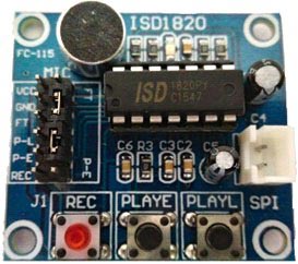
The module works on +5V and can be powered using the berg sticks on the left. It also has three buttons at the bottom which are Rec. button, PlayE. button and PlayL. button respectively. You can record your voice by pressing the Rec. button and play it using the PlayE button. The PlayL will play the voice as long as you hold the button. When interfacing with a MCU, we can use the pins on the left. These pins are 3V-5V tolerable and hence can be directly driven by Arduino/ESP8266. In our project we are controlling the PLAYE pin using the D8 pin of our Arduino module. So that we can play the recorded voice when a call is detected and received by the GSM module.
Circuit Diagram and Explanation:

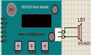
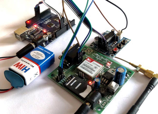
The complete circuit diagram of this Automatic Voice Call answering Machine project is given above. As you can see the connections are really simple. We power the GSM module with a 12V 1A adapter and Arduino with 9V battery, the ISD Voice module is powered by the +5V pin of the Arduino. As we know we can record anything on our voice module by pressing the rec button and this will get played when P-E is pressed, this audio has to be sent to the microphone of the GSM module. So we connect the speaker pin of the Voice module to the microphone pin of the GSM module.
Here, the Arduino and GSM module is connect serially, the Tx pin of Arduino is connected to pin 9 and Rx pin is connected pin 10. This will help the Arduino to listen to the GSM module. When a call arrives to the GSM module the Arduino will listen to it and ask the GSM module to answer the call. The Arduino makes sure that the call is active and then plays the recorded voice message on the voice module by making the pin 8 (Connected to P-E of voice module) go high for 200ms.
Programming your Arduino:
We know from the above paragraph what is the role of Arduino here is; now let us take a look at the code which does the same. The complete Arduino code of the project is given at the bottom of this page, further here I have spilt the code into small junks to explain it.
Before we precede any further install the GSM Library, kindly click on this Github GSM library link to download the library used in this project. You will get a zip file which has to be added to your Arduino library by Sketch -> Include Librarey -> Add .Zip file.
The first three lines of the code shown below are used to include the library to our code. We use the serial library and wire library because we are not using the default Rx and Tx pins of the Arduino to communicate with GSM module.
#include <sim900.h> //download librarey from https://github.com/Seeed-Studio/GPRS_SIM900
#include <SoftwareSerial.h> //default librarey
#include <Wire.h> //default library
We enable serial communication on pins 9 and 10 using the following line. This is made possible by the software serial library that we included above.
SoftwareSerial gprs(9,10);//TX,RX
Inside our setup function, we initialize the serial monitor at 9600 baud rate and GSM module is also initialized with 9600 Baudrate. The pin 8 which triggers the voice is declared as output pin.
void setup(){
  Serial.begin(9600); //Serial monitor works on 9600 baudrate for debugging
  sim900_init(&gprs, 9600); //GSM module works on 9600 baudrate
  pinMode(8, OUTPUT); //pin to turn on Voice
  Serial.println("Arduino - Automatic Voice Machine");
}
Next we have to create a function that could read and understand what the GSM module is saying through its Serial port. If we use simple serial read line like “gprs.read()” to read the message we will get them in form of ASCII decimal values, this will make no sense to us.
So the following function is used to convert these decimal values to strings by using string objects and then concatenate them to form a string. The final string value is stored in the variable Fdata, which is of type string and can be used to compare with any String values.
void check_Incoming()
{
    if(gprs.available()) //If GSM is saying something
    {
   Incomingch = gprs.read(); // Listen to it and store in this variable

  if (Incomingch == 10 || Incomingch ==13) //If it says space (10) or Newline (13) it means it has completed one word
  {Serial.println(data);  Fdata =data; data = ""; } //Print the word and clear the variable to start fresh
  else
  {
  String newchar = String (char(Incomingch)); //convert the char to string by using string objects
  data = data +newchar; // After converting to string, do string concatenation
  }
  }
}
The following lines are used for debugging, with these debugger lines you can send any AT commands from the Serial monitor of Arduino to GSM and also see what is responses on the serial monitor.
  if(Serial.available()){   //Used for debugging
    gprs.write(Serial.read());  //Used for debugging
  } //Used for debugging
As said earlier, the Arduino has to check if the GSM module is receiving any calls. This can be done by making the Arduino to check for “RING” because the GSM module will output RING in the event of a call according to the AT command list. When it finds a call it will wait for 5 seconds and send the command “ATA” to the GSM module, this will make the GSM module to answer the call and after answering it will respond with “OK”. The Arduino again waits for the “OK” acknowledgement and then turns the in Pin 8 high for 200ms to play the recorded voice from voice module.
  if (Fdata == "RING") //If the GSM module says RING
  {
  delay(5000); //wait for 5sec to create 3 ring delay.
  gprs.write ("ATA\r\n"); //Answer the call
  Serial.println ("Placed Received");  //Used for debugging
  while(Fdata != "OK") //Until call successfully answered
  {check_Incoming(); //Read what GSM modue is saying
  Serial.println ("Playing Recorded message");  //Used for debugging

  //Play the recored voice message
  delay(500);
  digitalWrite(8, HIGH); //Go high
  delay(200);     // wait for 200 msec
  digitalWrite(8, LOW); //Go low
  }

Working:
Once your code and hardware is ready, it is time for some fun. Power both the modules and press the REC button on the Voice module and record a message. This message can only be of 10 seconds long.
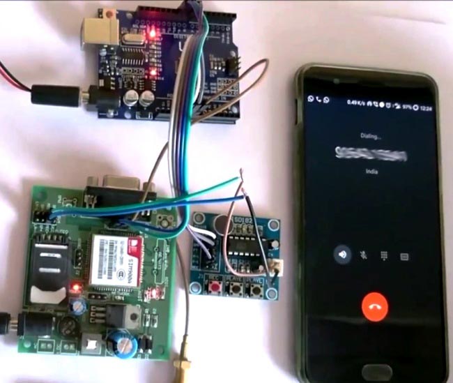
Now program your Arduino using the below given code and insert the SIM car in the GSM module, you should wait for at least 2 minutes now so that the GSM module could establish connection with your Network service provider. Once done you should see a red colour LED flashing once for every 3 seconds, this indicates that your SIM is ready to take calls. You can now try calling to this SIM card from any number and you should hear the recorded message after three continuous rings. The complete working of the project is shown in the video below.
Tadaaaaaa!!! Now you have your own Automatic voice call answering Machine and just go ahead and use it when required and amaze your friends and family with it.
Hope you enjoyed the project and build something similar, If you had any troubles post them on the comment section and I will help you out.
Complete Project Code
/*

Automatic Voice machine using Arudino and GSM900

Created by: Aswinth Raj B

Coded on: 22-9-2017

Website: www.circuitdigest.com

*/
#include <sim900.h> //download library from https://github.com/Seeed-Studio/GPRS_SIM900

#include <SoftwareSerial.h> //default library

#include <Wire.h> //default library
int Incomingch;

String data,Fdata;
 //Connect Tx pin of GSM to 9 of Arduino

//Connect Rx pin of GSM to 10 of Arduino

SoftwareSerial gprs(9,10);//TX,RX
void setup(){

  Serial.begin(9600); //Serial monitor works on 9600 baudrate for debugging

  sim900_init(&gprs, 9600); //GSM module works on 9600 baudrate

  pinMode(8, OUTPUT); //pin to turn on Voice

  Serial.println("Arduino - Automatic Voice Machine");

}
/*Function to read Incoming data from GSM to Arduino*/

void check_Incoming()

{

    if(gprs.available()) //If GSM is saying something

    {

   Incomingch = gprs.read(); // Listen to it and store in this variable


  if (Incomingch == 10 || Incomingch ==13) //If it says space (10) or Newline (13) it means it has completed one word

  {Serial.println(data);  Fdata =data; data = ""; } //Print the word and clear the variable to start fresh

  else

  {

  String newchar = String (char(Incomingch)); //convert the char to string by using string objects

  data = data +newchar; // After converting to string, do string concatenation

  }

  }

}

/*##End of Function##*/
void loop(){


   check_Incoming(); //Read what GSM module is saying


  if(Serial.available()){   //Used for debugging

    gprs.write(Serial.read());  //Used for debugging

  } //Used for debugging
  if (Fdata == "RING") //If the GSM module says RING

  {

  delay(5000); //wait for 5sec to create 3 ring delay.

  gprs.write ("ATA\r\n"); //Answer the call

  Serial.println ("Placed Received");  //Used for debugging

  while(Fdata != "OK") //Until call successfully answered

  {check_Incoming(); //Read what GSM module is saying

  Serial.println ("Playing Recorded message");  //Used for debugging
  //Play the recorded voice message

  delay(500);

  digitalWrite(8, HIGH); //Go high

  delay(200);     // wait for 200 msec

  digitalWrite(8, LOW); //Go low

  }

  }

}
Comments
Incoming voice record after recorded message is delivered
Can you please provide codes and equipment needed to record messages from the caller after playing recorded message once?
ISD 1820 Voice module does
ISD 1820 Voice module does not require a librarey. Just use the above code and you are all good to go
Help me in project of A6 GSM.module
Sir i have A6 GSM module and Arduino , please send me code for auto answeing a any call
sir I am doing the same
sir I am doing the same project but the call is not answered could you please help me to overcome the problem
Adding Call Screening to this answering machine
Hi to all,
How would you add a cicuit to this answering machine to ask caller to enter two initials of person they wish to reach, then if they know you the answering machine would take their call. This simple function would block all robo calls and most telemarketers. Thanks
Nice idea and yes it could be
Nice idea and yes it could be done. All you need is a DTMF module and then program the arduino accrdingly
Hi Aswinth Raj Ji,
Hi Aswinth Raj Ji,
Please help for auto dialing with recorded voice using ardiuno.

The projects you have posted are quite interesting and will be very useful for Technical students.