
In present time almost all the people are familiar with robots. Robots play a very important role in human life. Robots are a machine which reduces the human efforts in heavy works in industries, building etc. and makes life easy. We are here with our next robot that is Mobile or DTMF Controlled Robot. DTMF controlled Robot runs over mobile DTMF technology that exists in Dial tone. DTMF stands for Dual Tone Multiple Frequency. There are some frequencies that we use to create DTMF tone. In simple words by adding or mixing two or more frequencies generates DTMF tone. These frequencies are given below:

In given figure we can see two groups of different frequencies. When one upper and one lower frequencies mixed then a tone is created and that tone we call Dual Tone Multiple Frequency.
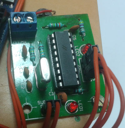
Required Components
- Arduino UNO
- DC Motor
- Mobile Phone
- DTMF decoder Module
- Motor Driver L293D
- 9 Volt Battery
- Battery Connector
- Aux wire
- Robot Chasis with wheel
- Connecting wires
What is DTMF?
DTMF is a Dual Tone Multiple Frequency decoder module which has a MT8870 DTMF decoder IC which decodes DTMF tone signal to digital signal that are acceptable for arduino digitally. Here an aux wire is needed for connecting DTMF module to phone.
Block Diagram for DTMF Controlled Robot using Arduino

Remote section: This section’s main component is DTMF. Here we get a tone from our cellphone by using aux wire to DTMF Decoder IC namely MT8870 which decodes the tone into digital signal of 4bit.
Control Section: Arduino UNO is used for controlling whole the process of robot. Arduino reads commands sent by DTMF Decoder and compare with define code or pattern. If commands are match arduino sends respective command to driver section.
Driver section: driver section consists motor driver and two DC motors. Motor driver is used for driving motors because arduino does not supply enough voltage and current to motor. So we add a motor driver circuit to get enough voltage and current for motor. By collecting commands from arduino motor driver drive motor according to commands.
Circuit Diagram and Working Explanation

Circuit digram for Arduino based DTMF Controlled Robot is very similar with our other robot like PC controlled robot, Line Follower, Gesture Controlled Robot, etc.. Here one motor driver is connected to arduino for driving robot. Motor driver’s input pin 2, 7, 10 and 15 is connected at arduino digital pin number 6, 5, 4 and 3 respectively. Here we have used two DC motors to driver robot in which one motor is connected at output pin of motor driver 3 and 6 and another motor is connected at 11 and 14. A 9 volt Battery is also used to power the motor driver for driving motors. A DTMF decoder attached with this circuit and this decoder is plugged into a mobile using an aux wire for receiving command or DTMF Tone. DTMF decoder pin D0-D3 is directly connected with Arduino’s pin number 19,18,17,16. Two 9 Volt batteries are used to power the circuit in which one is used for power the motors, connected at motor driver IC pin number 8. And another battery is connected to power the remaining circuit.
Working of DTMF Controlled Robot
DTMF controlled robot run by some commands that are send via mobile phone. We are here using DTMF function of mobile phone. Here we have used the mobile phone to show working of project. One is user mobile phone that we will call ‘remote phone’ and second one that are connected with Robot’s circuit using aux wire. This mobile phone we will call ‘Receiver Phone’.
First we make a call by using remote phone to receiver phone and then attend the call by manually or automatic answer mode. Now here is how this DTMF controlled robot is controlled by cell phone:
When we presses ‘2’ by remote phone, robot start to moving forward and moving continues forward until next command comes.

When we presses ‘8’ by remote phone, robot change his state and start moving in backward direction until other command comes.

When we press ‘4’, Robot get turn left till next command exicuted.

When we press ‘6’, robot turned to right.

And for stopping robot we pass‘5’.

Programming Explanation
In program first of all we have defined output pins for motors and Input pins for DTMF decoder output as in INPUT for Arduino.

And then in setup set motor pin as OUTPUT and DTMF decoder output pins as INPUT.

After that we read DTMF decoder output and then compare with defined values by using “if” statement and perform relative operation.

There are five conditions in this DTMF controlled Robot that are giving below:

We write program according to above table conditions.
Complete Project Code
#define m11 3

#define m12 4

#define m21 5

#define m22 6
#define D0 19

#define D1 18

#define D2 17

#define D3 16
void forward()

{

   digitalWrite(m11, HIGH);

   digitalWrite(m12, LOW);

   digitalWrite(m21, HIGH);

   digitalWrite(m22, LOW);

}
void backward()

{

   digitalWrite(m11, LOW);

   digitalWrite(m12, HIGH);

   digitalWrite(m21, LOW);

   digitalWrite(m22, HIGH);

}
void left()

{

   digitalWrite(m11, HIGH);

   digitalWrite(m12, LOW);

   digitalWrite(m21, LOW);

   digitalWrite(m22, LOW);

}
void right()

{

   digitalWrite(m11, LOW);

   digitalWrite(m12, LOW);

   digitalWrite(m21, HIGH);

   digitalWrite(m22, LOW);

}
void Stop()

{

   digitalWrite(m11, LOW);

   digitalWrite(m12, LOW);

   digitalWrite(m21, LOW);

   digitalWrite(m22, LOW);

}
void setup()

{

  pinMode(D0, INPUT);

  pinMode(D1, INPUT);

  pinMode(D2, INPUT);

  pinMode(D3, INPUT);
  pinMode(m11, OUTPUT);

  pinMode(m12, OUTPUT);

  pinMode(m21, OUTPUT);

  pinMode(m22, OUTPUT);

}
void loop()

{
  int temp1=digitalRead(D0);

  int temp2=digitalRead(D1);

  int temp3=digitalRead(D2);

  int temp4=digitalRead(D3);


  if(temp1==0 && temp2==1 && temp3==0 && temp4==0)

  forward();
  else if(temp1==0 && temp2==0 && temp3==1 && temp4==0)

  left();
  else if(temp1==0 && temp2==1 && temp3==1 && temp4==0)

  right();
  else if(temp1==0 && temp2==0 && temp3==0 && temp4==1)

  backward();
   else if(temp1==1 && temp2==0 && temp3==1 && temp4==0)

  Stop();

}
Comments
You can buy a DTMF module from your local hardware shop or there are various websites like ebay from where you can buy it online.
You have to buy from "Amazon.In".
which ic is used in dtmf decoder
Interesting project. However, there seems to be a big gap in the area of getting the audio signal from the cell phone to the DTMF module. " an aux wire is needed" does not explain much.
If you notice carefully, there is another cell phone, that is placed on the Robot and AUX wire has been used to connect that cell phone to DTMF module.
plz i need a clear image of circuit diagram pins connection to arduino
Just click on the Circuit Diagram, it will get enlarge and opens in new Tab.
Dtmf contolled robot with microcontroller, dtmf -dual tone muliti-frequency
can u tell me whole procedure of how to burn code in arduino uno.....thnks
what library files u added while coding for dtmf decoder
Use Arduino IDE software (Arduino Nightly : https://www.arduino.cc/en/Main/Software) to burn the code into Arduino.
this code is not working after uploading
Projects is properly tested, check you circuit connections and use mentioned components.
i didnt get where aux wire got connected .it is not even shown in circuit diagram
Hey in program code Pin D0,D1,D2,D3 are specified where as in circuit diagram pin D6,D5,D4,D3 are given. Can any one explain it to me
D0,D1,D2,D3 are for DTMF module, not for Arduino. Code means D0,D1,D2,D3 of DTMF module are connected to Arduino pins 19, 18,17,16. Please read the Description, Code and Circuit before comment.
Code is not working after uploading.....plz sir can u mail me correct code
please tell that where the program need to be feed either in ardino or DTMF module
No need of programming for dtmf ic .So feed yr program in ardino (burner port).
tell about RPM speed of dc motor(150 or 200) and dc supply.
Thanks for your detailed explanation,Can u explain how to connect the audio jack with DTMF module
DTMF module has connector to connect the two wires from 3.5 mm audio jack. Further you can check wires of 3.5 mm jack in this article: Small Loudspeaker for Computer or Cell Phone You need to connect Ground and Left/right audio wires from audio jack.
please tell me the specifications of arduino used in this project
i cant find DTMF module in shops in my city ,, but there is MT8870 ic only ,, can i use it only ??? ,, or it should be programmed first ???
Yes you can, but then you need to connect other components with 8870 chip like Crystal etc. Check this project where we used MT8870 chip with its other needed circuitry: DTMF Based Home Automation
Hey...
I have one question in my mind.. You are using analog pins A2 - A5. and in void loop you are reading data digitally.. how is it possible? Analog pin only takes analog input and dtmf module decodes input digitally. So digital data should be read by Arduino.
I am also failing to drive the motors as per this information mentioned by you... please give me directions. my all connections are well checked as per your instructions.Please help us...
You can use analog pins in digitalRead()/digitalWrite() function in Arduino to read or write digital data.
I want this mini projects based on pic microcontroller
Very good....thank u.....I made it.....in just 10 min.....no problem in coding or circuit
Plz send Me pic microcontroller coding
PLEASE tell us is it possible to make this project i m very interesting in making this project.....
give me your whatsapp number
can i directly do the coding in turbo 7...ll it directly save in arduino...r shld i any other procedure for that...could you plz guide me
You are saying that the output of dtmf module is digital, but how you are connecting it with analog pins of arduino??
Please read all the previous comments before asking questions, we might have answered them already.
My motor driver(l293d) board does not have enable pins
Is it work properly ? .
i want to make the calling using sim900A module as well as control using dtmf command set.
since i tried using AT+DDET=1 but my module showing error. could you advice me.
#define D0 19
#define D1 18
#define D2 17
#define D3 16 in this code u r defining the pins as 16,17,18,19 where r those pins in audrino..help me to understand
in this ..in l298d module both en1 and end are connected to +5v volt..is it corret ?
how to connect aux cable with DTMF and mobile phone. and which type of cell phone use for this project .
tnx . you are best !!!
How to use in project of DC motor ? How many Voltage in DC Motor ?
Is it possible to get vedio feedback from receiver phone to controller phone???
I want to get vedio feedback from attached Android mobile phone to calling Android mobile phone, by using skype vedio call. Is it possible, if i use seme circuit diagram and same ardiuno code?? Plz replay.. its very urgent.
In the circuit diagram where should I connect the mobile phone using audio jack?
In the circuit diagram the DTMF module is shown as a block. The actual DTMF module will have a audio jack pin to which the mobile phone can be connected.
the project is good but will it work with normal l298d
I have some questions:
1. Do we use a 3.5mm TRS Aux cable to connect the DTMF Module to the Receiver phone?
2. Will this project work with this MT8870 Module?
https://www.ebay.ie/itm/MT8870-DTMF-Tone-Decoding-Module-Voice-Arduino-Raspberry-PI-Flux-Workshop/111774276711?ssPageName=STRK%3AMEBIDX%3AIT&_trksid=p2057872.m2749.l2649?
3. Can you please explain "attend the call by manually or automatic answer mode" in more detail?
I'm using a Samsung S6 for the remote phone. Would a Nokia 130 work ok for the receiver phone?
Thank you.
1. You can use 3.5mm Aux cable
2. Yes it will
3. There is an android phone which can automatically answer calls, install it and your phone will answer the call automatically then you can use the DTMF to navigate
ThanQ its WORKING
Could you "whistle" the dtmf tones into the remote phone?
All those r very gud concepts but hw I can download the PDF of particular projects????
Please send making video
i have given all the connections..still the motor has not get power supply.....
i am using l298n driver .....we have give the connections for enable or it will work without enable connections..?
May I know how connections are done from strting to end.
how can I simulate this circuit .

Where can i bay this DTMF-Module?
Thanks,
Jack