To turn on a Thyristor, there are various triggering methods in which a trigger pulse is applied at its Gate terminal. Similarly, there are various techniques to turn off a Thyristor; these techniques are called Thyristor Commutation Techniques. It can be done by bringing the Thyristor back into the forward blocking state from the forward conduction state. To bring the Thyristor into forward blocking state, forward current is reduced below the holding current level. For power conditioning and power control, a conducting Thyristor must be commutated properly. The Thyristor commutation is the process whereby it stops conducting by reducing the forward current to a level below the holding current. This important technique in power electronics provides for active control and power conditioning in a broad range of electronic circuits - choppers, inverters, and rectifiers are common examples.
In this tutorial, we will explain the various Thyristor Commutation Techniques. We already explained about Thyristor and its Triggering Methods in our previous Article.
Table of Contents
Complete Classification of Thyristor Commutation Techniques
There are mainly two techniques for Thyristor Commutation: Natural and Forced. The Forced commutation technique is further divided into five categories, which are Class A, B, C, D, and E.
Below is the Classification:
- Natural Commutation
- Forced Commutation
- Class A: Self or Load Commutation
- Class B: Resonant-Pulse Commutation
- Class C: Complementary Commutation
- Class D: Impulse Commutation
- Class E: External Pulse Commutation
Natural Commutation of Thyristor: AC Circuit Applications
Natural commutation of thyristor occurs only in AC circuits, and it is named so because it doesn’t require any external circuit. When a positive cycle reaches zero and the anode current is zero, immediately a reverse voltage (negative cycle) is applied across the Thyristor, which causes the Thyristor to turn OFF. Natural thyristor commutation is a behaviour found in AC circuits that allows the thyristor to turn off without needing any external commutation circuit. Thyristors' natural commutation occurs when the anode current decreases to zero during the negative half cycle.
Key Factors of Natural Communication
- Only to be found in AC circuits with sinusoidal profiles
- No need for additional commutation components
- Often found in phase-controlled rectifiers and cycloconverters
- The thyristor turns off at the zero current crossing point
A Natural Commutation occurs in AC Voltage Controllers, Cycloconverters, and Phase Controlled Rectifiers.

Forced Commutation of Thyristor: DC Circuit Solutions
Forced commutation of thyristor becomes necessary in DC circuits where natural current zero crossings don't exist. As we know, there is no natural zero current in DC Circuits, such as natural commutation. So, Forced Commutation is used in DC circuits, and it is also called DC commutation. It requires commutating elements like inductance and capacitance to forcefully reduce the anode current of the Thyristor below the holding current value, which is why it is called Forced Commutation. Mainly, forced commutation is used in Chopper and inverter circuits. Forced commutation is divided into six categories, which are explained below:
1. Class A: Self or Load Commutation
Class A is also called “Self-Commutation”, and it is one of the most used techniques among all Thyristor commutation techniques. In the circuit below, the inductor, capacitor and resistor form a second-order underdamped circuit. Class A commutation of thyristor, also known as self-commutation or load commutation, is the most widely used forced commutation technique.

When we start supplying the input voltage to the circuit, the Thyristor will not turn ON, as it requires a gate pulse to turn ON. Now, when the Thyristor turns ON or forward biased, the current will flow through the inductor and charge the capacitor to its peak value or equal to the input voltage. Now, as the capacitor gets fully charged, the inductor's polarity gets reversed, and the inductor starts opposing the flow of current. Due to this, the output current starts to decrease and reaches zero. At this moment, the current is below the holding current of the Thyristor, so the Thyristor turns OFF.
2. Class B: Resonant-Pulse Commutation
Class B commutation is also called Resonant-Pulse Commutation. There is only a small change between Class B and Class A circuits. In class B, the LC resonant circuit is connected in parallel, while in Class A, it’s in series. Class B commutation of thyristor employs a parallel LC resonant circuit to generate commutating current.

Now, as we apply the input voltage, the capacitor starts charging up to the input voltage (Vs), and the Thyristor remains reverse-biased until the gate pulse is applied. When we apply the gate pulse, the Thyristor turns ON, and now the current starts flowing from both directions. But then the constant load current flows through the resistance and inductance connected in series, due to their large reactance.
Then, a sinusoidal current flows through the LC resonant circuit to charge the capacitor with the reverse polarity. Hence, a reverse voltage appears across the Thyristor, which causes the current Ic (commutating current) to oppose the flow of the anode current IA. Therefore, due to this opposing commutating current, when the anode current is less than the holding current, the Thyristor turns OFF.
3. Class C: Complementary Commutation
Class C commutation is also called Complementary Commutation. As you can see in the circuit below, there are two Thyristors in parallel, one is the main and the other is auxiliary. Class C commutation of thyristor utilizes two thyristors working in complementary fashion - when one turns on, it turns off the other

Initially, both thyristors are in the OFF condition, and the voltage across the capacitor is also zero. Now, as the gate pulse is applied to the main Thyristor, the current will start flowing from two paths: one is from R1-T1, and the second is from R2-C-T1. Hence, the capacitor also starts charging to the peak value equal to the input voltage, with the polarity of plate B positive and plate A negative.
Now, as the gate pulse is applied to the Thyristor T2, it turns ON and a negative polarity of current appears across the Thyristor T1, which causes T1 to turn OFF. And, the capacitor starts charging with the reverse polarity. Simply, we can say that when T1 turns ON, it turns OFF T2, and as T2 turns ON, it turns OFF T1.
4. Class D: Impulse Commutation
Class D commutation is also called Impulse Commutation or Voltage Commutation. As Class C, Class D commutation circuit also consists of two Thyristors T1 and T2, and they are named as main and auxiliary, respectively. Here, the diode, inductor, and auxiliary Thyristor form the commutation circuit. Class D commutation of thyristor is also known as impulse commutation or voltage commutation.

Initially, both thyristors are in the OFF state, and the voltage across capacitor C is also zero. Now, as we apply the input voltage and trigger the Thyristor T1, the load current starts flowing through it. And, the capacitor starts charging with polarity of plate A negative and plate B positive.
Now, as we trigger the auxiliary Thyristor T2, the main Thyristor T1 turns OFF and the capacitor starts charging with the opposite polarity. When it gets fully charged, it causes the auxiliary Thyristor T2 to turn OFF, because a capacitor does not allow the flow of current through it when it gets fully charged.
Therefore, the output current will also be zero because at this stage, both the Thyristors are in the OFF state.
5. Class E External Pulse Commutation: Advanced Control Method
Class E commutation is also called External Pulse Commutation. Now, you can see in the circuit diagram that the Thyristor is already in forward bias. So, as we trigger the Thyristor, the current will appear at the load.

The capacitor in the circuit is used for the dv/dt protection of the Thyristor, and the pulse transformer is used to turn OFF the Thyristor.
Critical Commutation Condition
Now, when we give a pulse through the pulse transformer, an opposite current will flow in the direction of the cathode. This opposite current opposes the flow of the anode current, and if IA – IP < IH, the Thyristor will turn OFF.
Where IA is the Anode current, IP is the pulse current, and IH is the holding current.
Applications of Thyristor Commutation in Power Electronics
Thyristor commutation techniques find widespread applications across various domains of commutation in power electronics:
| Commutation Type | Primary Applications | Industry Sectors |
| Natural | Rectifiers, AC Controllers | Power supplies, Motor drives |
| Class A | Basic Choppers, Simple Inverters | DC motor control, Battery chargers |
| Class B | Resonant Converters | Induction heating, RF applications |
| Class C | Bridge Inverters, Bidirectional Choppers | UPS systems, Motor drives |
| Class D | High-frequency Choppers | Switching regulators, DC drives |
| Class E | Precision Control Systems | Laboratory equipment, Medical devices |
Understanding thyristor commutation techniques is fundamental for designing efficient power electronic systems.
Frequently Asked Questions About Thyristor Commutation Techniques
⇥ 1. What is the primary distinction between natural and forced commutation?
In AC circuits, natural commutation occurs passively when current goes through zero, whereas in DC circuits, forced commutation is how circuits using inductors and capacitors will provide for an artificial means to bring the current below the holding level.
⇥ 2. What is the rationale behind the need for commutation in thyristor circuits?
Because thyristors cannot be turned off with gate control and maintain conduction, it becomes necessary to reduce the current below the holding level to then regain control over the power and the switching capabilities in the system.
⇥ 3. How does Class C cutting off commutation occur?
Class C utilises two thyristors. When the first thyristor is turned on and the voltage appears across the second thyristor (which was already on), that reverse voltage is sufficient to force the second thyristor to cut off. This complementary activity allows for bidirectional power transfer in a regulated manner.
⇥ 4. What are the aspects of Class E exterior pulse commutation?
Class E allows for a very exact time to effect the commutation process received via an external pulse transformer. Class E is appropriate for use in cases where precise control becomes very important, as in medical equipment or laboratory instrumentation requiring exact timing in switching controls.
⇥ 5. In what situations is natural commutation generally applied?
Natural commutation is applied in applications that are inherently alternating current (AC) applications, such as phase-controlled rectifiers for direct current (DC) power supplies and control of DC power, as well as AC voltage controllers for lighting and heating, and cycloconverters for frequency conversion.
⇥ 6. What considerations are involved in the choice of the commutation topology?
The choice will be dependent on the circuit type (AC/DC), frequency of switching requirements, tolerance to complexity, cost limits, as well as application-specific requirements like bidirectional power flow or precise timing control.
⇥ 7. How does resonant pulse commutation (class B) work in comparison to self-commutation?
The class B technique is used with parallel LC resonant circuits to generate a sinusoidal commutation current, while class A uses series LC circuits with natural oscillatory decay, which allows class B to operate continuously in applications.
⇥ 8. What safety consideration(s) must be addressed related to thyristor commutation circuits?
The important considerations include the proper selection of dv/dt protection capacitors, proper voltage ratings for commutation components, thermal and cooling considerations for high-frequency commutation, and a fail-safe commutation backup that will save the thyristor in case the thyristor commutation does not operate or fails.
Innovative Projects using Thyristor
For a deeper understanding of how these Thyristor are applied, explore the project links listed below.
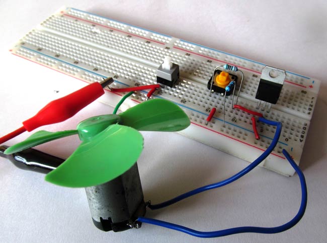
DC Motor Control using Thyristor
In this project, we are going to show you how to control a load or DC motor using a Thyristor. You can replace the DC motor with any other DC load and control the any DC circuit.
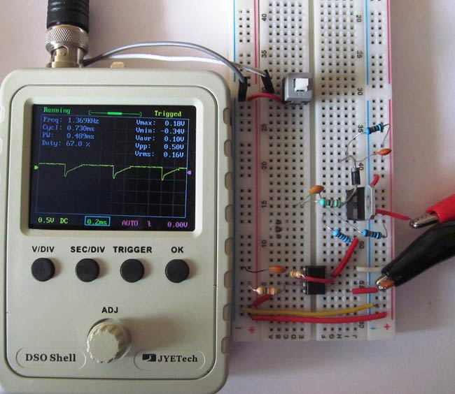
Thyristor Switching using Snubber Circuit
In this project, we will show you how a Snubber circuit protects a Thyristor from overvoltage or overcurrent. The circuit is consisting of Snubber circuit across the Thyristor and a frequency generator circuit using 555 timer IC.
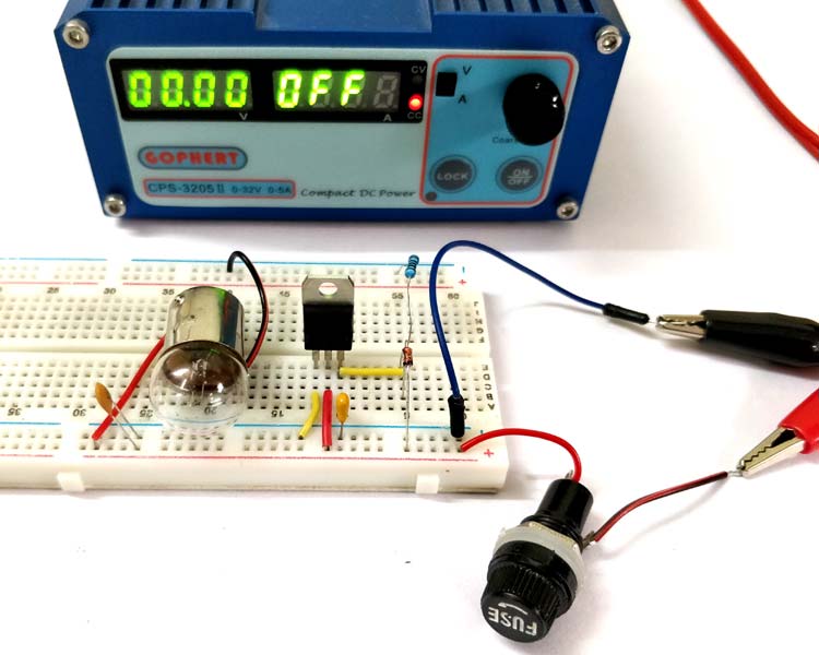
In this tutorial, we will discuss the Crowbar Circuit, which is a type of overvoltage protection circuit and is commonly used in electronic devices. We will also practically create this circuit and verify how it works in real life.


