
This DIY tutorial is all about making our home lighting smart and fun without any complicated steps. We can connect a standard 12V LED strip to a tiny wi-fi chip and build our own ESP32 WLED controller custom smart lighting system, which can be completely controlled from a smartphone or computer.
This DIY ESP32 based WLED controller guide skips the days of writing complex coding lines to program the light patterns and goes with a ready-made, open-source software called WLED. Once we power on our physical build, the system automatically connects to our home Wi-Fi network; it's a DIY ESP32-WLED Controller Setup. You can also check out similar ESP32 Projects and IoT projects done previously here at Circuit Digest.
Quick answer: An ESP32 WLED controller is a DIY smart lighting driver that pairs an ESP32 microcontroller with the open-source WLED firmware to control addressable RGB (WS281X/CX2811A) LED strips over Wi-Fi, no coding required, controllable from a phone, browser, or Home Assistant.
- Build type: ESP32-based WLED controller, no custom firmware coding needed
- Control method: Wi-Fi (HTTP/JSON API), phone app, or web dashboard
- LED protocol: WS281X / CX2811A addressable RGB (also supports APA102, WS2801, PWM RGB)
- Setup time: Under 15 minutes from flashing to first light output
- Best for: Smart home ambient lighting, retail displays, gaming/desk setups
Table of Contents
How Does the ESP32 Based WLED Controller Work?
In this project, we can send commands from a smartphone or the web dashboard of WLED to control the colours in addressable RGB lighting. When a user slides their fingers across the colour wheel, it sends the HTTP or JSON request over local Wi-Fi, which is intercepted by ESP32. Inside the ESP32, these Network packets are decoded and converted to digital data. WLED organises these data sequentially, 24 bits (red – 8 bits, green – 8 bits, blue – 8 bits) for every pixel in the group.
The ESP32 pushes this data out in 3.3V Digital Logic; the internal logical level shifter in the addressable RGB light converts the 3.3V logic to 5V logic. The first 24 bits received are stripped off to control the 3 physical LEDs connected by PWM (Pulse Width Modulation) to control their brightness. It also has a timer feature to turn off the addressable LED after an hour. The successive bits are regenerated and sent to the next chip. Here is the Voice-Controlled Smart Home Assistant project, where we showcased how voice recognition is incorporated with the RGB light.
Components Required for the ESP32 WLED Controller DIY Build
Below is the list of components required to build this ESP32 WLED controller project, with their descriptio
| S.no | Components | Specification | Quantity |
| 1. | Microcontroller | ESP32 Dev Kit | 1 |
| 2. | Resistor | 330Ω | 1 |
| 3. | Capacitor | (100μF-1000μF) Electrolytic | 1 |
| 4. | Power Supply | 12V | 1 |
| 5. | Addressable RGB LEDs | WS281X / CX2811A | 1 |
ESP32 WLED Controller Wiring Diagram and Schematic
The schematic illustrates all the essential connections required to build the ESP32-powered WLED smart LED controller. Follow the wiring carefully to ensure stable power delivery and reliable wireless control of your addressable LED strip.
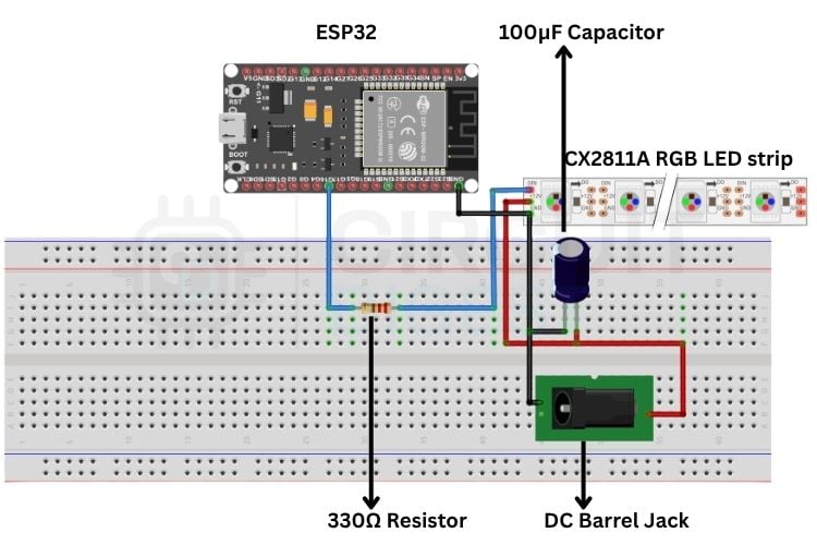
The ESP32 WLED controller Schematic setup is quite simple. From GPIO 16(RX2) 330Ω resistor is connected; the other end of the resistor is connected to the DIN of the CX2811A driver addressable RGB LEDs. The 100μF capacitor is placed between GND and +12V, and GND and +12V are given to CX2811A, addressing RGB LEDs. The GND of the ESP32 and the power supply are commonly grounded. You can also check out the Smart WLED Clock with RTC, PIR, Audio feedback and Environmental Monitoring project in CircuitDigest, which integrates addressable RGB LEDs with clock setup.
Step-by-Step ESP32 WLED Controller Setup Guide
The ESP32 WLED Controller setup process, step-by-step configuration, is listed below. This makes an unprogrammed ESP32 a fully automated smart lighting system.
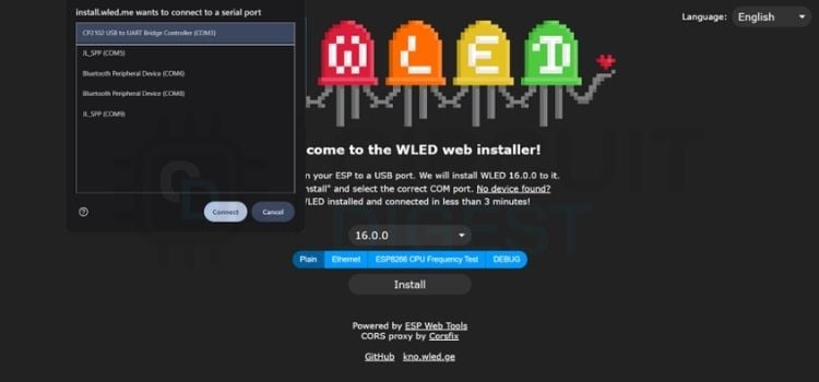
Step 1⇒ Flash the WLED Firmware
Connect the ESP32 to the PC, open the https://install.wled.me/ website, click install, it shows many COM ports, select the CP2102 USB to UART bridge Controller (COM3) and click install. It will be installed. It will display a flash option to erase the ESP32 memory. Click erase, and it will be flashed and programmed for WLED.
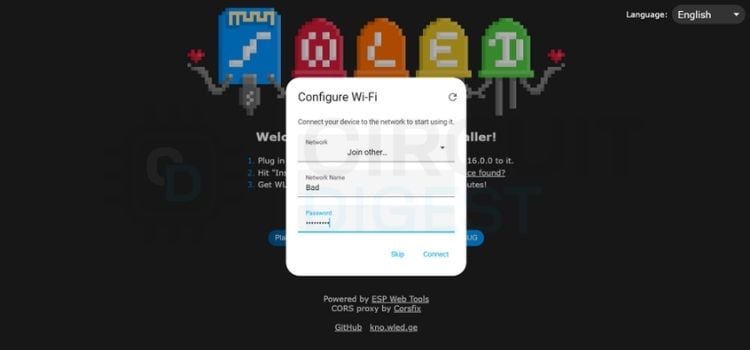
Step 2⇒ Configure the Wi-Fi Network
Then the Configure Wi-Fi menu opens, where you give your local Wi-Fi name and password and click Connect. The ESP32 will be connected to the Wi-Fi Network you entered. Double-check the network name and password. If it is not connected.
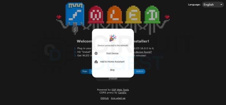
Step 3⇒ Access the WLED Web Dashboard
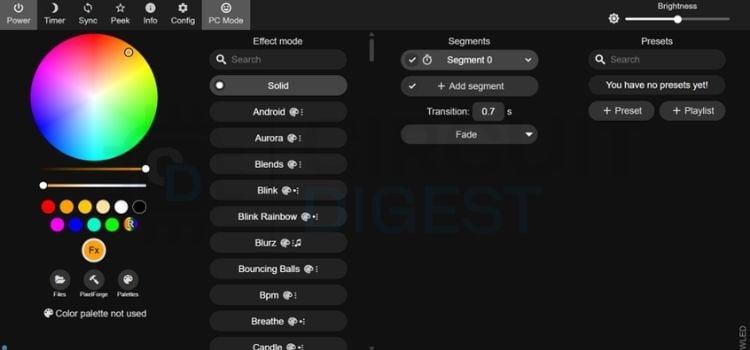
If the Wi-Fi is connected, the menu will open like Device connected to the network and click Visit Device to open the WLED Web Dash.
WLED Web Dash opens and shows menus to customise the RGB light, change Wi-Fi, adjust the Colour palette, set timer options, and sync with your Home Assistant, etc.
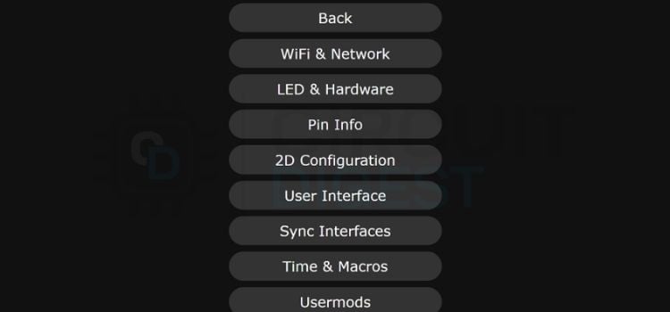
Step 4⇒ Open the Configuration Hub
Click the config tab at the top of the screen; it opens a menu from which we can able to change Wi-Fi, change hardware and software parameters, sync, and timer, etc.
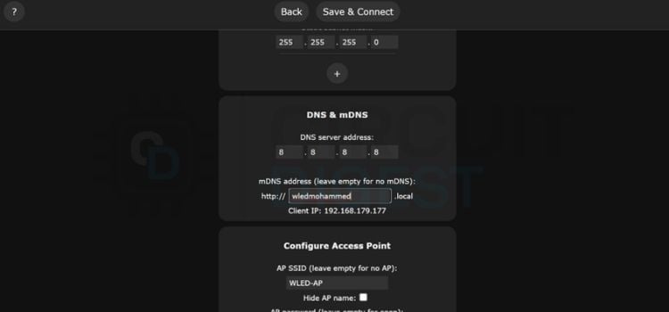
Step 5⇒ Set the mDNS Address
Click the Wi-Fi and Network tab. From there, we can change the mDNS address to any name you want to access the website, for example, the name it is set to is wledmohammed. From there, we can access our WLED through the name we set previously.
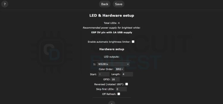
Step 6⇒ Configure LED and Hardware Settings
Click the LED and Hardware setup tab. Here, we need to change the type to WS281X, uncheck the Enable automatic brightness limiter, select the GPIO to 16 and select the number of LEDs you need to turn ON. These setups can also be done by Mobile Phone using the WLED application. If the strip light has 4 pins (V+, GND, DATA, CLK), choose APA102 or WS2801. If the strip has 5 pins (V+, R, G, B, W), choose PWM RGB. We can also able to choose the number of LEDs to glow.
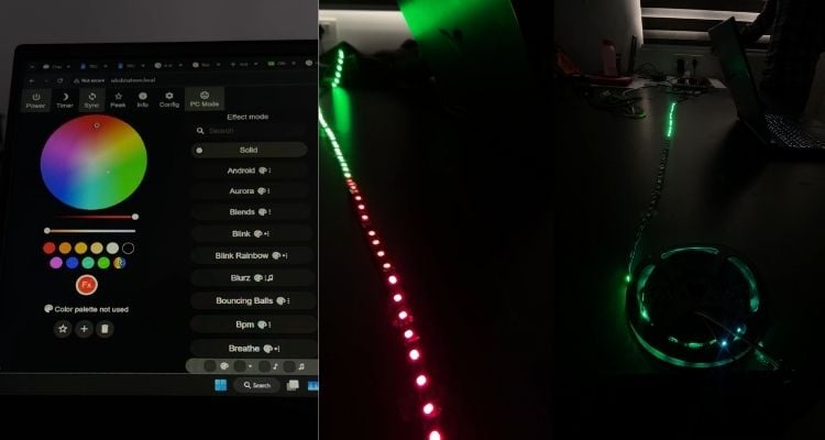
Output
The Final physical circuit successfully powers the 12V addressable LED strip using the ESP32. When the ESP32 is turned ON, it hosts a WLED Web page. Where we can control the lighting of the strip using a colour Palette disc on a webpage, also by setting a timer function, we can be able to turn it OFF and ON at a preset time.
Live Demo: Smart Wi-Fi LED Controller with ESP32
Experience the real-time performance of the ESP32 WLED controller, showcasing wireless LED control, smooth animations, and smart lighting features.
ESP32 WLED Controller Manual: Troubleshooting Common Issues
| Issue | Fix |
| How to properly ground the circuit? | The GND terminal of the RGB light and the 12V supply ground need to be connected to a common ground. |
| What power rating does the addressable RGB light need? | The CX2811A IC drives 3 Red, 3 Green, and 3 Blue LEDs together. Each LED draws 3.2V, totalling 9.6V; the remaining 2.4V is dropped internally/externally. |
| Selected colour doesn't match the strip's actual colour? | Change the colour order in the dashboard/app — try GBR, BGR, RBG, or BRG. BRG is the correct setting for most CX2811A strips. |
| ESP32 connects to the app, but the strip won't respond? | If using a phone hotspot for Wi-Fi credentials, turn off mobile data while the hotspot is on. |
Real World Application:
∗ Smart Home Ambient Lighting: Integrated cove lighting for living rooms, false ceilings, and under-cabinet kitchen lights.
∗ Commercial Display Branding: Dynamic lighting for storefront windows, product display shelves, and digital signage boards in retail outlets.
∗ Gaming Setups and Entertainment Zone: Immersive PC desk backlighting, home theatre setups, or studio backgrounds.
Frequently Asked Questions About ESP32 WLED Controller
⇥ Why are the strip colours not changing?
It will happen due to the missing GPIO connection to the strip, and also make sure the ESP32 GND and Power Supply GND are common-grounded.
⇥ Do we need to connect the GNDBreaker Pin to the Power Jack?
There is no need to connect the GNDBreaker Pin in the Power Jack because it is used only in case of Battery is used.
⇥ Which WLED setting needs to be used for the CX2811A strip?
Set the LED type to WS281X, as it uses the same protocol. The only difference is that you set the colour order to BRG
⇥ Why is the web page not opening?
If the Power is not supplied to the ESP32 will not host the Webpage; you need to be connected to the same network as the ESP32 is connected.
⇥ Why is the WLED Controller not working even after giving all the connections?
Check the arrows of the strip light; it is needed to be pointed away from the ESP32.
⇥ Are the PIN in Web Page and the physical connection needed to be same?
The pins should match; if it doesn’t match, the data will not be sent to the strip light.
Explore More LED Projects
Discover a collection of DIY LED projects using Arduino, ESP8266, NeoPixel, and WS2811 addressable LED strips. Learn LED interfacing, interactive lighting effects, and IoT-based RGB lighting through practical maker projects.

Interfacing WS2812B Neopixel LED Strip with Arduino
So, in this Arduino interfacing tutorial series, we are going to look at how to interface such LEDs with Arduino. We will be interfacing the WS2812B LEDs, which are also known as NeoPixel.

How to make an Interactive 2-player Arcade Game using WS2811 LED Strip and Arduino Nano
In this blog, we will learn how to create this fun 2-player game made using Arduino. We will learn about the WS2811 LED strip, and then we will learn about the design, electronics, as well as coding of this game.

ESP8266 and Neopixel LED Strips Based RGB Night Lamp Controlled By Blynk App
So, today we have a great project for you people that is a Wi-Fi-controlled Ironman mask. So, today we have a great project for you people that is a Wi-Fi-controlled Ironman mask.
