

The integration of addressable LEDs with the WLED firmware has revolutionized DIY lighting projects, allowing for complex visual effects with minimal to no coding. However, most standard WLED-based clocks face significant limitations, such as time-drift during internet outages and continuous power consumption regardless of room occupancy and no alarms. To address these issues, this project demonstrates the construction of an advanced feature rich smart clock.
Table of Contents
- Features
- Components Required
- Circuit Diagram
- Power and Programming Input
- ESP32 Microcontroller Circuit
- Sound Module Circuit
- Arrangement of LEDs
- └ Back Side of PCB
- 3D View of Front and Back Side Of PCB
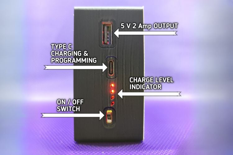
- Real World Image After Assembly
- 3D View of CAD Files
- Programming / STL / Gerbers
- Overall Look and Web UI
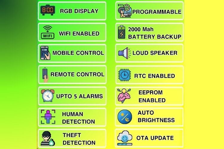
Features
- Set RGB Colours
- Temperature
- Humidity
- Dusk Sensor
- Motion Detection
- 5 Audio Alarms
- Theft Detection
- 1 Theft Alarm Audio
- Buzzer
- Battery Backup
- Fully Programmable
- RTC Support
- Wifi Connectivity
- Configure Via Web App
- IR Remote Control
- Power Saving Mode
Components Required
The following components are required to build this advanced smart clock. It is recommended to use high-quality modules to ensure long-term stability.
| Component | Specification | Quantity |
| Microcontroller | ESP32 Wroom -32 - 4 Mb | 1 |
| LED Matrix/Strip | WS2812B Addressable RGB LEDs | 73 LEDs |
| RTC Module | DS3231 (with CR2032 Battery) | 1 |
| Motion Sensor | PIR Sensor (MH-SR 602 or HC-SR501) | 1 |
| Temp/Hum Sensor | DHT11 Sensor | 1 |
| IR Receiver | TSOP1838 or equivalent | 1 |
| Capacitor SMT | 16v/100 uf | 1 |
| Capacitor SMD | 100uf (0805) 22uf (0805) | 8 2 |
| Resistor | 10k (0805) 1k (0805) 5.1K (0805) | 10 5 2 |
| LDR | 22R (0805) 10k or 100k (0805) | 1 1 |
| LEDs | Any Colour (0805) | 4 pcs |
| JST Connector | 2.54mm 6 Pin JST THT Male & Female | 1 each |
| Power Path IC | IP5306_IC | 1 |
| USB To TTL | CH340C_IC | 1 |
| Transistor | BC817 or equivalent | 1 |
| Sound Module | JQ6500 or DF player | 1 |
| Buzzer | Generic THT Buzzer 12mm x 9mm 3.3/5v | 1 |
| LDO Regulator | AMS 1117 3.3 v LDO | 1 |
| Relay | HF46F 5V DC Relay | 1 |
| USB port | Type C 16-P SMD Type A 4-P SMD | 1 1 |
| Digital transistor | UMH11N or similar | 1 |
| Buttons | 4 pin smd 6mm x 6mm x 6mm | 7 |
| Battery | 18650 lithium-ion battery with holder | 1 each |
| Speaker | Mylar speaker 0.5W 8Ohm 40mm (4-ohm 3 watt Recommended) | 1 |
| Power Supply | 5V 3A DC Adapter | 1 |
| Enclosure | 3D Printed (PLA/PETG) | 1 |
| PCB | Printed Circuit board | 2 main+sensor |
Circuit Diagram

Power and Programming Input
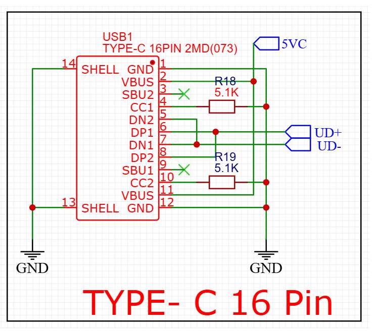
We are using a 16-pin type c port as it offers reciprocal, a reversible connection for data and powering.
Let's see how connections are made.
1. Power Supply (VBUS & GND)
- VBUS (Pins 2 & 11): These are the positive power lines. They are tied together and labeled here as 5VC, providing the 5V power
- GND (Pins 1 & 12): These are the ground pins, connected to the common ground.
- SHELL (Pins 13 & 14): The metal outer casing of the connector is also grounded to provide shielding and physical stability.
2. USB 2.0 Data (UD + & UD -)
- DP1/DP2 (Pins 6 & 8): Data Plus. These are bridged together to the UD+ label.
- DN1/DN2 (Pins 7 & 5): Data Negative. These are bridged together to the UD- label.
- Why are they bridged? Since USB-C is reversible, bridging the DP and DN pairs ensures that data connectivity works regardless of which way you plug in the cable, similar for power.
3. Configuration Channel (CC1 & CC2)
- Pins 4 & 10: These are the most critical pins for USB-C. In this diagram, they are pulled to VBUS through 5.1k resistors (R18 & R19) this makes sure type c to type c cable provide 5 v power. Missing of those resistors will only work for type A to Type c cable.
USB to TTL Converter
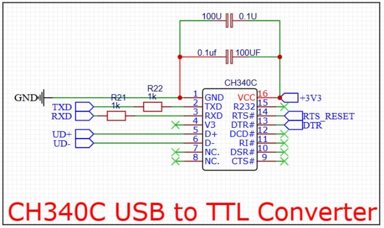
CH340C USB-to-UART (TTL) Serial Converter circuit. is the "bridge" that allows your computer to talk to the ESP32 chip. When you plug your clock into a PC to upload the firmware, this chip converts the USB signals into a language the ESP32 understands.
Here is the breakdown of how this circuit functions:
1. USB Interface (The Left Side)
- UD+ and UD-: These connect directly to the UD+ and UD- pins we saw on your USB-C connector. This is where the raw USB data enters the chip.
- GND: Common ground for signal stability.
2. Power and Decoupling (Top and Right)
- VCC (Pin 16): Connected to +3V3. This chip is being powered by a 3.3V regulator (standard for ESP32 projects).
- Decoupling Capacitors: You see two sets of capacitors (100 uf and 0.1\uf ) in parallel.
- The 100uf capacitor acts as a reservoir to handle power spikes.
- The 0.1uf capacitor filters out high-frequency noise.
- Note: The diagram shows them doubled up; usually, one of each is sufficient right next to Pin 16.
3. UART Serial Data (TXD and RXD)
- TXD (Pin 2): Transmit Data. This sends data from the computer to the ESP32's RX pin.
- RXD (Pin 3): Receive Data. This receives data from the ESP32's TX pin.
- 1k\ohm Resistors (R21, R22): These are inline protection resistors. They prevent "back-powering" the chips and protect against short circuits if two pins accidentally try to output data at the same time.
4. Auto-Reset Circuit (RTS and DTR)
- RTS_RESET and DTR (Pins 14 & 13): These are the "handshake" pins.
- In the world of ESP32/Arduino, these pins are used to automatically put the ESP32 into Bootloader Mode.
- When you click "Upload" in your IDE, the computer toggles these pins to reset the ESP32 and pull GPIO 0 low, so you don't have to manually press buttons on the board to flash the firmware.
Power Management Circuit
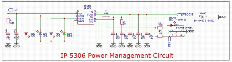
This schematic features the IP5306, a highly integrated multi-function power management SOC (System on Chip) that is the "Power Bank" circuit. It allows the clock to run off an 18650 Li-ion battery, charges that battery when USB is plugged in, and boosts the battery voltage to a stable 5V for the LEDs and ESP32.
Here is the breakdown of the circuit sections:
1. Battery Charging & Power Input
- VIN (Pin 1): Receives 5V power from your USB-C connector (5VC). This charges the connected battery.
- BAT (Pin 6): Connects to the positive terminal of the 18650 battery. The IP5306 manages the charging cycle (Constant Current/Constant Voltage) to ensure the battery is charged safely.
- C12, C13 (Input Caps): Filter the incoming USB power to prevent voltage ripples.
2. Synchronous Boost Converter (The 5V Output)
- VOUT (Pin 8): This is the boosted output labeled 5VBOOST. When the USB is unplugged, the chip takes the battery's approx 3 to 4.2 V and boosts it to a steady 5V.
- SW (Pin 7) & L1 (1uH Inductor): These are the core components of the switching regulator. The inductor stores energy in a magnetic field to push the voltage up to 5V.
- Output Capacitors (C1 to C5): A massive bank of capacitors to ensure the 5V supply is extremely stable, which is critical because addressable LEDs (WS2812B) are very sensitive to power fluctuations.
3. Monitoring & Interaction
- LED1–LED4 (Pins 2, 3, 4): These pins drive the four LEDs on the left. They provide a visual "Fuel Gauge," showing battery capacity in increments of 25%, 50%, 75%, and 100%.
- KEY (Pin 5): Connected to a momentary push-button.
- Short press: Wakes up the chip and displays battery level.
- Double press: Usually turns the output off (enters standby/low power mode).
- USB Plugged In: 5VC => IP5306 =>Charges Battery AND output 5V. powers the Clock
- USB Unplugged: Battery => IP5306 (Boosts) => 5V powers the Clock.f
Power Switch and Voltage Regulator
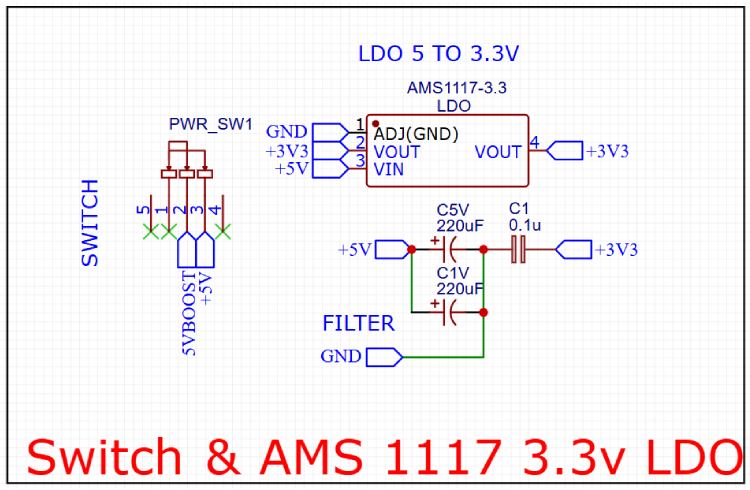
The power management stage is designed to convert the incoming 5V supply into a stable 3.3V rail required for the ESP32 Microcontrolller
1. Input Selection and Switching (PWR_SW1)
The circuit uses a multi-pin slide switch (PWR_SW1) to control the power flow. When the switch is toggled, it bridges the input to the internal +5V rail, effectively acting as the main power switch for the entire device.
2. Low Dropout Regulator (AMS1117-3.3)
To derive the 3.3V rail, an AMS1117-3.3 LDO (Low Dropout Regulator) is utilized. This is a common choice in ESP32 projects due to its ability to provide up to 800mA of current, which is sufficient to handle the power spikes during Wi-Fi transmission.
- Pin 3 (VIN): Receives the switched 5V input.
- Pin 2 & 4 (VOUT): Provides the regulated 3.3V output.
- Pin 1 (GND/ADJ): Connected to the common ground to establish the voltage reference.
3. Filtering and Decoupling Stage
To ensure the output is free from high-frequency noise and voltage ripples (which can be caused by the fast switching of the WS2812B LEDs or IP5306 ic ), a robust filtering network is implemented:
- Bulk Capacitance: Two large 220\uF electrolytic capacitors (labeled C5V and C1V) are placed on the 5V input line. These act as energy reservoirs to prevent voltage drops when the load suddenly increases.
- High-Frequency Decoupling: 0.1\uf ceramic capacitor (C1) is placed on the 3.3V output line. This capacitor is critical for filtering out low-amplitude, high-frequency noise that the larger electrolytic capacitors cannot catch, ensuring the ESP32 receives a clean signal.
Boot and Reset Circuit
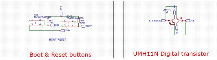
1. Boot & Reset Buttons (Manual Control)
This is the "fail-safe" part. It allows you to manually interact with the ESP32 hardware.
- RST Button: Connected to the ESP32's EN (Enable/Reset) pin. When pressed, it shorts the pin to GND, forcing the chip to restart.
- BOOT Button: Connected to GPIO0. For an ESP32 to accept new code, GPIO0 must be held at GND while the chip resets.
- Pull-up Resistors (RR1, RB1 - 10k\Ohm) These are vital. They tie the pins to +3V3 by default. This ensures the chip stays "On" and in "Run Mode" unless you explicitly press a button to pull the signal to Ground.
2. UMH11N Digital Transistor (Automatic Control)
The UMH11N is a specialized dual-transistor package. It automates the "Button Mashing" required to flash firmware. It takes the RTS_RESET and DTR signals from the CH340C chip we discussed earlier and converts them into Reset and Boot commands.
How the Logic Works:
The transistors act as electronic switches. They are wired in a specific cross-coupled configuration often called the "ESP32 Auto-Program Circuit":
- Automated Upload: When you click "Upload" in your browser or IDE, the CH340C toggles RTS and DTR. This circuit translates those signals to pull the RST and BOOT lines low in the correct sequence.
- The Benefit: You don't have to open the 3D-printed enclosure or hold down tiny buttons every time you want to update your Code; the computer handles it all through the USB-C cable.
5 V Output for External Use
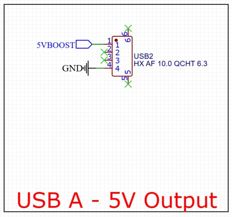
Circuit Breakdown
- 5VBOOST (Pin 1): This pin is connected directly to the output of your IP5306 Power Management IC. Since the IP5306 is a boost converter, it can provide a steady 5V even when the clock is running solely on its internal 18650 battery.
- GND (Pin 4): Connected to the common system ground to complete the circuit.
- Data Pins (Pins 2 & 3): These are marked with green "X" symbols, meaning they are Not Connected (NC). Because there are no data lines, this port cannot transfer files; it is strictly for "dumb" charging or powering devices in an emergency.
- Mechanical Shielding (Pins 5 & 6): These represent the metal housing of the USB-A connector, typically soldered to the PCB for physical strength and grounded to reduce electromagnetic interference.
ESP32 Microcontroller Circuit
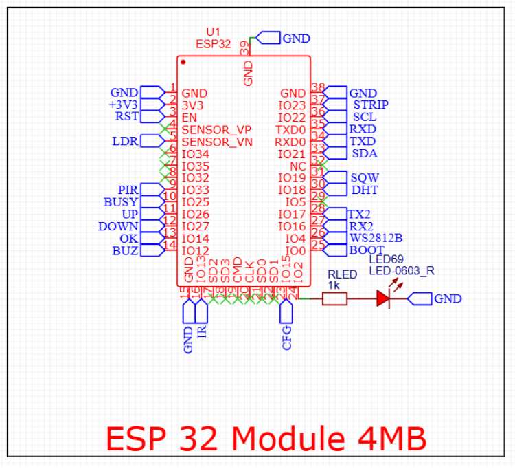
Pin Mapping & Peripheral Connectivity
1. Communication Interfaces
- I2C Bus:
- SDA: IO21 (Pin 33)
- SCL: IO22 (Pin 36)
- UART: TXD0/RXD0: Standard programming/debug port (Pins 34, 35).
- TX2/RX2: Secondary UART interface on IO17 and IO16 (Pins 27, 28).
- SPI (Flash/Internal): Pins 17–22 is reserved for the internal flash memory connection (SD2, SD3, CMD, CLK, SD0, SD1).
2. Sensors & Input
- LDR (Light Dependent Resistor): Connected to SENSOR_VN (Pin 5) for analog light sensing.
- DHT (Temp/Humidity): Assigned to IO18 (Pin 30).
- PIR (Motion): Assigned to IO33 (Pin 9).
- IR (Infrared): Connected to IO13 (Pin 16).
Navigation Buttons:
- UP: IO26 (Pin 11)
- DOWN: IO27 (Pin 12)
- OK: IO14 (Pin 13) f
3. Outputs & Indicators
- STRIP: IO23 (Pin 37) connected to Relay Circuit for cutting power to LEDs
- WS2812B: IO4 (Pin 26) Data pin for LEDs
- Buzzer (BUZ): Connected to IO12 (Pin 14).
- Status LED: A red 0603 LED (LED69) is connected to IO2 (Pin 24) through a 1k\Ohm current-limiting resistor (RLED).
- SQW: A square wave output signal (goes to DS3231 RTC) is connected to IO19 (Pin 31).
4. System Control
- BOOT: Pin IO0 (Pin 25) is broken out for flashing mode selection.
- EN (Reset): The RST line (Pin 3) handles the module reset logic.
- CFG: A configuration pin assigned to IO15 (Pin 23).
- BUSY: A status feedback pin on IO25 (Pin 10).
Sound Module Circuit
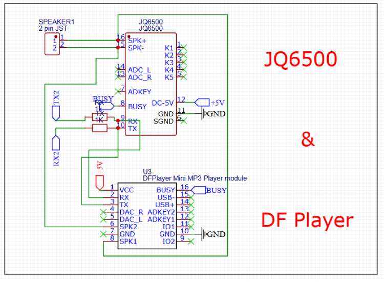
We have designed the PCB footprint to be compatible with both modules, allowing us to choose the most available or cost-effective option during assembly.
- Shared Control: Both modules use a UART interface (TX2/RX2). We included 1k/ohm resistors on the data lines to protect the modules from 5V logic spikes and reduce serial noise.
- Dual-Compatible Audio: The speaker outputs from both the JQ6500 (SPK+/-) and the DFPlayer (SPK1/2) are routed to a single 2-pin JST connector. This ensures that regardless of which Module we solder, the audio reaches the speaker.
- Status Monitoring: We tied the BUSY pins together. This lets our code monitor if the module is currently playing audio, regardless of which hardware is used.
- Power: Both footprints are tied to a regulated +5V rail with a shared ground to maintain signal integrity.
NOTE: Adding custom audio in jq6500
You will need 6 Audios, Audio 1,2,3,4,5 corresponds to 5 Alarm and Audio 6 is for Theft Alarm. All are in mp3 format, and all combined audio size should be below or up to 2000kb / 2 mb, most important is to enter audio name as 001 - 002 - 003 … where audio 1 is 001 and audio 2 is 002 and so on. Now you can Upload it in jQ6500 Module.
RTC Circuit
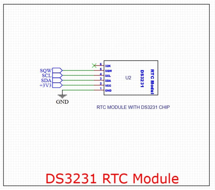
We use this to maintain highly accurate timekeeping for the system, even if the main power is lost.
Connections:
- I2C Communication: We use the SDA (Pin 3) and SCL (Pin 4) lines to interface with the ESP32 for time data transfer.
- Square Wave (SQW): Pin 5 is connected to the SQW net. We can use this to trigger precise 1Hz interrupts or as an alarm output.
- Power: The module is powered by the +3V3 rail (Pin 2) with a common GND (Pin 1).
- 32K Output: Pin 6 (32KHz output) is left unconnected (marked with an 'X'), as we don't require that specific frequency for this design.
Control Buttons
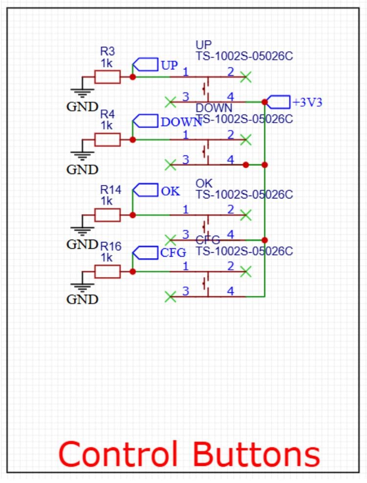
Control Button array used for user input (UP, DOWN, OK, CFG). We have implemented an Active-High logic configuration for these tactile switches.
How it Works
- Pull-Down Resistors: We use 1k\Ohm resistors (R3, R4, R14, R16) connected to GND. This ensures the signal lines stay at 0V (Low) when the buttons are not pressed, preventing "floating" pins that could cause false triggers.
- Switching Logic: One side of each switch is connected to the +3V3 rail.
- Triggering: When we press a button, it closes the circuit and pulls the corresponding GPIO pin (UP, DOWN, OK, or CFG) to 3.3V (High).
Relay Circuit
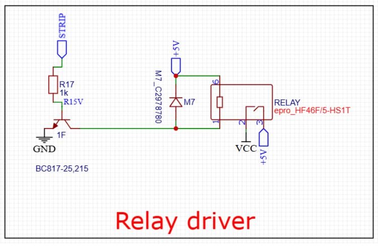
Relay Driver circuit allows a low-power microcontroller signal to switch a high-power load using a BC817 NPN transistor.
How it Works
- Switching Mechanism: We apply a signal to the STRIP net. This current passes through the 1k\Ohm base resistor (R17) to the transistor, which then acts as a switch, connecting the relay coil to GND.
- Flyback Protection: We've included an M7 diode in parallel with the relay coil. This is crucial as it protects our transistor from high-voltage spikes (back-EMF) generated when the relay coil is deactivated.
- Power: The relay coil is powered by a +5V rail, while the contacts (Pins 2 and 3) are set up to switch a separate VCC load when the relay is energized.
- We are using relay here to cut power to LEDs so that WS2812 ICs inside leds don't consume power when leds are not lit.
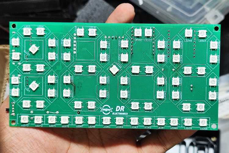
WS2812B LEDs Circuit
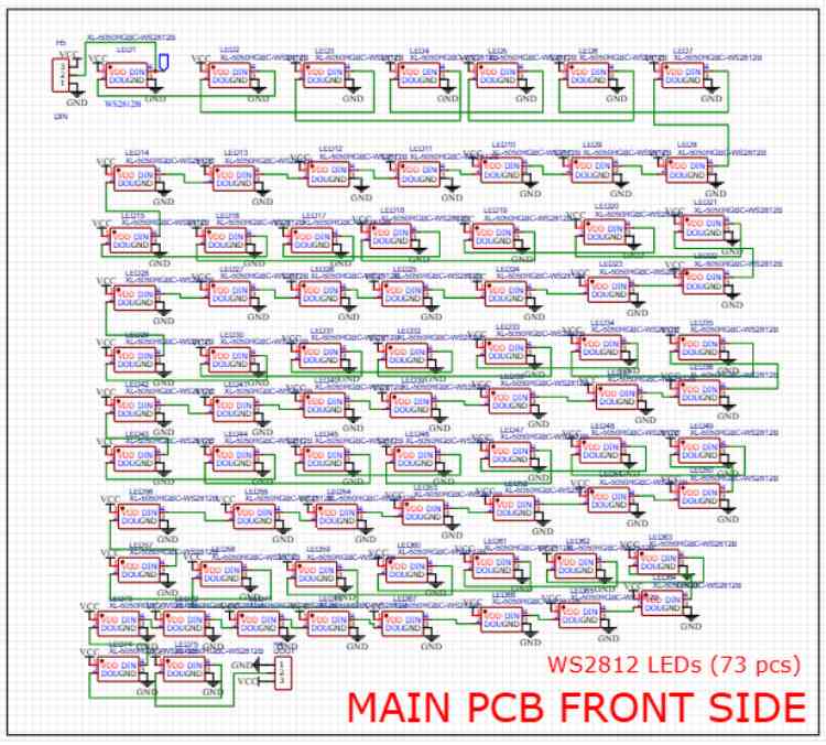
This schematic features an addressable WS2812B RGB LED matrix consisting of 73 individual LEDs. We’ve designed this for a high-density visual display, for a clock face
Key Design Features
- Daisy-Chain Configuration: We’ve connected the LEDs in a serial data line. The DOUT (Data Out) of one LED feeds directly into the DIN (Data In) of the next. This allows us to control all 73 LEDs using just a single GPIO pin from the ESP32.
- Power Distribution: All LEDs share a common VCC and GND rail. Since each WS2812B can draw up to 60mA at full white brightness, we must ensure our power supply can handle roughly 4.4A 73x60 Ma for this board.
- Connectors: We included 3-pin headers at the start (DIN) and end (DOUT) of the chain. This makes it easy to link multiple PCBs together or inject power at different points to prevent voltage drop.
NOTE: Because we have 73 LEDs in a tight "snake" pattern, we should include decoupling capacitors (typically 100nF) near the VCC pin of each LED on the PCB layout to filter out switching noise and keep the data signal clean across the entire chain. And the power consumption can reach up to 5 amps so we will set max brightness to 50 percent to avoid power failure.
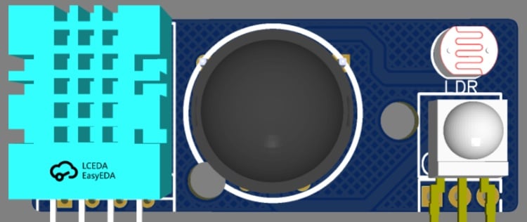
Sensors Circuit
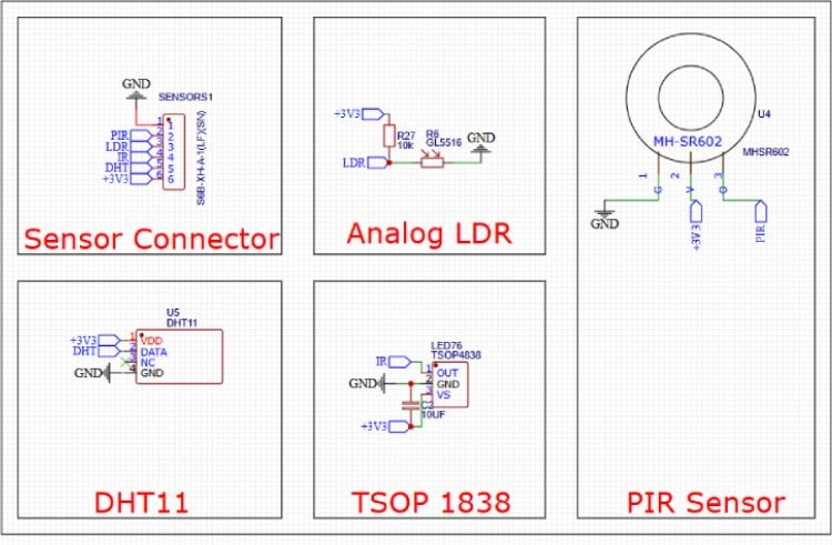
1. Sensor Connector (S6B-XH-A-1) 2.54 x 6 pin
We have included a 6-pin JST-XH connector as a centralized interface for external Main clock Board.
Pins: PIR, LDR, IR, DHT, +3V3, and GND.
2. Analog LDR (Light Detection)
We are using a GL5516 photoresistor in a voltage divider circuit with a 10k\Ohm resistor (R27).
Operation: As the light intensity changes, the resistance of the LDR varies, altering the voltage at the LDR net. This analog signal is then read by the ESP32’s ADC to determine ambient brightness, controlling led brightness accordingly.
3. PIR Sensor (Motion Detection)
The design utilizes an MH-SR602, which is a compact, high-sensitivity passive infrared sensor.
Connectivity: It operates on +3V3 and sends a digital high trigger to the PIR net whenever motion is detected.
4. DHT11 (Climate Sensing)
For temperature and humidity, we’ve integrated the DHT11.
- Data Line: It uses a single-bus digital protocol connected to the DHT net. We’ve powered it via the +3V3 rail to ensure compatibility with our logic levels.
5. TSOP 1838 (Infrared Receiver)
To enable remote control functionality, we included the TSOP4838/1838 IR receiver.
Filtering: We added a 10\uf decoupling capacitor (C2) across the power pins (VS and GND). This is critical for filtering out power supply noise, which ensures the IR data signal remains clean and accurate for decoding.
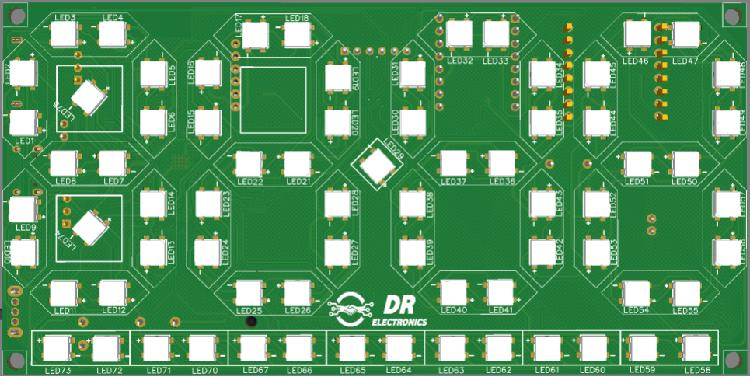
Arrangement of LEDs
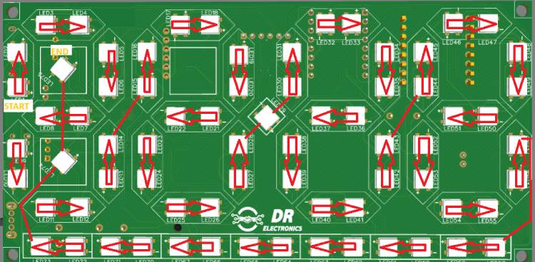
Description: The 2-layer PCB layout highlighting the optimized routing for WS2812b leds in Daisy chain showing START & END ie Data in AND Data Out
Front Side of PCB
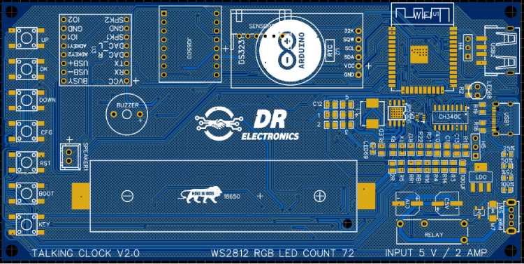
PCB Layout and Routing:
Description: Arrangement of ESP32 and all other components like RTC, Battery holder, type C port, etc.
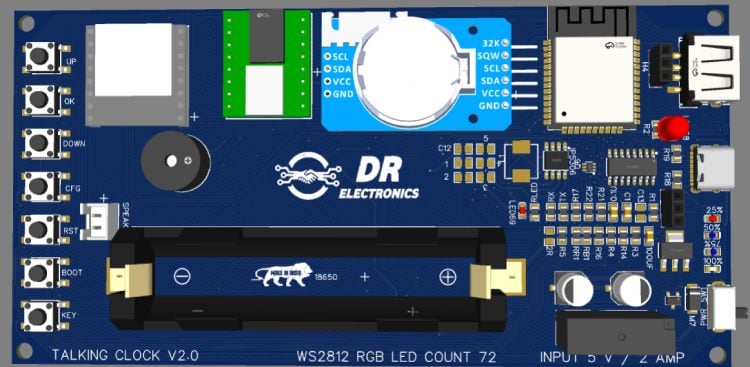
3D View of Front Side Of PCB
Sensor PCB
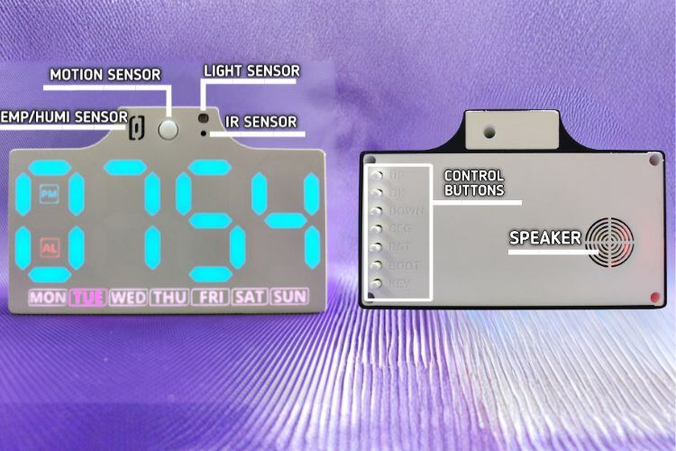
Real World Image After Assembly
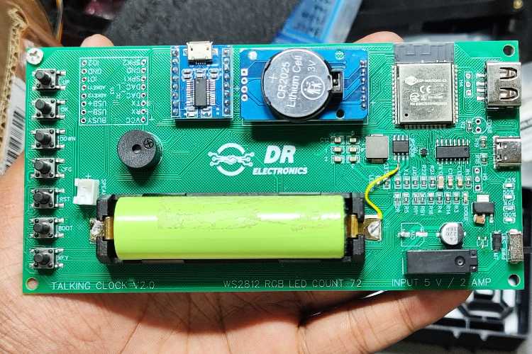
Soldering and Assembly
Description: The PCB during the assembly phase. Surface-mount components were soldered first, followed by through-hole modules like the DS3231 RTC and the PIR sensor to maintain a low-profile form factor.
NOTE: There is space for 2 Capacitor near Relay they are connected parallel to support high current surge, but soldering 2 of them was shorting out the IP5306 5v output damaging it permanently. hence the yellow wire jumper seen in image is used to recover burnt track due to short (using single capacitor works flawlessly but the clock will reboot whenever external power is disconnected)
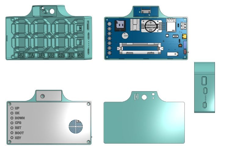
3D View of CAD Files
Programming / STL / Gerbers
All programming files, gerbers, stl and Instructions are posted on GitHub repository of Smart WLED Clock. Code is written in ARDUINO IDE and is inspired from WLED open-source code. PCB Designed in EASY_EDA and 3D Modelling in ONSHAPE


Setting up the clock after programming.
- After successful programming RESTART Clock.
- Press CONFIG Button once, it will open Access Point (AP Mode)
- Connect to Access Point “Clock-EFXXXXX”
- It will open WEB UI For clock config (if didnt just open Wled app)
- Set all parameter of your choice
- And connect clock to Home WiFi
- Click save & exit wifi settings (ONLY then This will close AP Mode) And connect to given wifi network
- Now connect your mobile to same home wifi and open WLED App, click (+) Icon and you will see Same name as “Clock-EFXXXXX”, Click Add, now it will fetch time automatically from selected NTP Server and you can set all parameters anytime without reaching clock from App itself.
- If by mistake wrong WiFi Credentials are given, you can press Config button again any time to open Access Point Mode.
Overall Look and Web UI
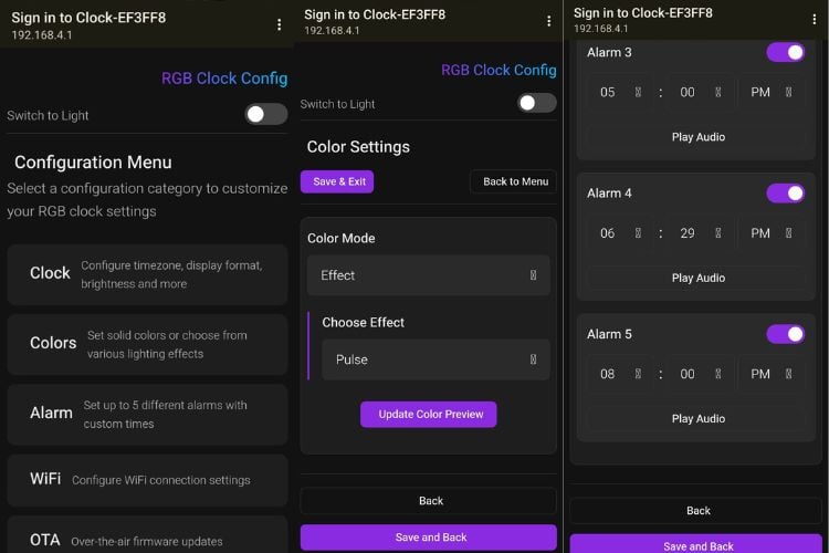
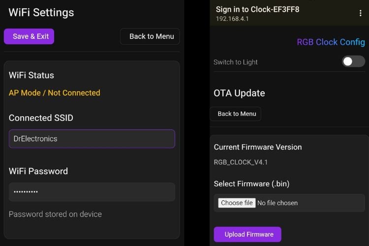
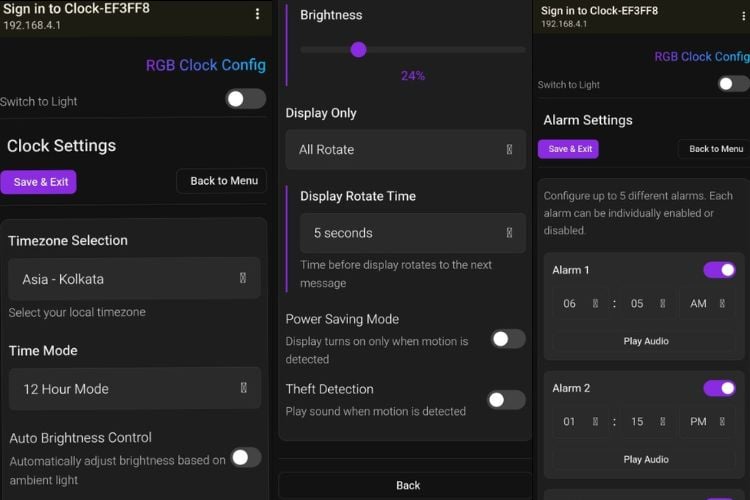
Complete Project Code
//parition scheme : Minimal SPIFFS
/*
* Auther : Vishal Soni (@electrodonut)
* ESP32 Board : V3.3.4
* FastLED : v3.10.3
* RTClib : v2.1.4
* DHT sensor Adafruit : v1.4.6
* JQ6500_Serial : (Link: https://github.com/sleemanj/JQ6500_Serial)
*/
/*++++++++++++++ Libraries ++++++++++++++++*/
#define FASTLED_ALLOW_INTERRUPTS 1
#define FASTLED_INTERRUPT_RETRY_COUNT 0
#include <Arduino.h>
#include <FastLED.h>
#include <Wire.h>
#include "RTClib.h"
#include <WiFi.h>
#include <ESPmDNS.h>
#include <WebServer.h>
#include <DNSServer.h>
#include <Preferences.h>
#include <ArduinoJson.h>
#include "DHT.h"
#include <JQ6500_Serial.h>
#include <Update.h>

#include "webpage.h"
#include "timezone.h"
/*++++++++++++++ Wifi ++++++++++++++++*/
String wifiSSID;
String wifiPassword;
WebServer server(80);
Preferences prefs;
Preferences wifiPrefs;
char mdnsHostname[32];
// Timezone handling
String tzString;  // Will hold POSIX timezone string
bool wifiConnected = false;
bool timeSynced = false;
unsigned long lastUpdateTime = 0;
bool apModeActive = false;
bool mdnsRunning = false;
bool serverRunning = false;

DNSServer dnsServer;
// const char* AP_PASSWORD = "12345678";  // ≥8 chars or set nullptr for open AP
const char *AP_PASSWORD = nullptr;
;  // ≥8 chars or set nullptr for open AP

/*++++++++++++++ Pin Declaration ++++++++++++++++*/
#define LED_PWR_RELAY 23
#define DATA_PIN 4
#define DHTPIN 18  // Digital pin connected to the DHT sensor
#define LDR 39
#define PIR 33
#define BUSY_AUDIO 25  //1 busy 0 free
#define UP_BUTTON 26
#define DOWN_BUTTON 27
#define OK_BUTTON 14
#define CONFIG_BUTTON 15
/*++++++++++++++ Display ++++++++++++++++*/
#define NUM_LEDS 73
CRGB leds[NUM_LEDS];         // Define the array of leds
int display_cycle_time = 3;  //seconds
unsigned long lastTimeDisplaySwitch = 0;
int Display_Value = 0;
#define MAX_DISPLAY_VALUES 3
String displayOnly;  // "all", "time", "temperature", "humidity"
/*++++++++++++++ Buttons ++++++++++++++++*/
const unsigned long debounceDelay = 50;  // ms
struct Button {
 uint8_t pin;
 bool lastStableState;
 bool lastReading;
 unsigned long lastDebounceTime;
 const char *name;
};
Button buttons[] = {
 { UP_BUTTON, LOW, LOW, 0, "UP" },
 { DOWN_BUTTON, LOW, LOW, 0, "DOWN" },
 { OK_BUTTON, LOW, LOW, 0, "OK" },
 { CONFIG_BUTTON, LOW, LOW, 0, "CONFIG" }
};
const int buttonCount = sizeof(buttons) / sizeof(buttons[0]);
/*++++++++++++++ Sound define ++++++++++++++++*/
#define Alarm1Sound 1
#define Alarm2Sound 2
#define Alarm3Sound 3
#define Alarm4Sound 4
#define Alarm5Sound 5
#define TheftAlarmSound 6
uint8_t alarm_volume = 30;
/*++++++++++++++ Alarm System ++++++++++++++++*/
// Alarm structure for 5 alarms
struct Alarm {
 bool enabled;
 int hour;
 int minute;
 int sound_num;
 unsigned long snooz_minute;
 int back_up_h;
 int back_up_m;
};
#define ALARM_COUNT 5
Alarm alarms[ALARM_COUNT] = {
 //true/false(enable/disale) , hour , minute, sound number, snooz minute, backup hour and backup minte?
 { false, 7, 0, Alarm1Sound, 1, 7, 0 },    // Alarm 1 - default 7:00 AM snooze 1 minute
 { false, 8, 0, Alarm2Sound, 10, 8, 0 },   // Alarm 2 - default 8:00 AM snooze 10 minute
 { false, 9, 0, Alarm3Sound, 5, 9, 0 },    // Alarm 3 - default 9:00 AM snooze 5 minute
 { false, 10, 0, Alarm4Sound, 0, 10, 0 },  // Alarm 4 - default 10:00 AM
 { false, 13, 0, Alarm5Sound, 0, 13, 0 }   // Alarm 5 - default 1:00 PM
};
bool alarm_is_active = 0;
bool is_snooz_pressed = 0;
int current_active_alarm = 0;
/*++++++++++++++ PIR ++++++++++++++++*/
bool first_time_on_before_pir = 0;
bool is_pir_on = 1;
bool turn_on_relay = 0;
int time_out_for_led_off = 1;  // 1 minute on
// int time_out_for_led_off = 1000 * 5 * 1;  // 1 minute on
unsigned long lastTimePirOn = 0;
JQ6500_Serial mp3(Serial2);
bool is_theft_on = 0;
int theftSoundTimeout;  // seconds
bool theftTimingEnabled;
struct TheftTime {
 uint8_t hour;
 uint8_t minute;
} theftStartTime, theftEndTime;
bool theftTimingInRange = 0;  //if in range turn it 1
bool Theft_active = 0;        //whill 1 if theft audio playing
/*++++++++++++++ LDR ++++++++++++++++*/
bool autoBrightness = 1;
int minRawValue = 4095;  // Expected in complete darkness
int maxRawValue = 1425;  // Expected in bright light
int minLedBrightness = 10;
int maxLedBrightness = 255;
int rawValue = 0;
int brightness;
// int lightLevel = 0;
/*++++++++++++++ DHT 11 ++++++++++++++++*/
bool is_temp_in_f = 0;
#define DHTTYPE DHT11
DHT dht(DHTPIN, DHTTYPE);
float humidity = 0;
float temperature = 0;
/*++++++++++++++ LEds ++++++++++++++++*/
// Define segments as reusable objects
CRGBSet hour_1(leds + 0, 14);   // First hour digit (LEDs 0-13, 14 LEDs total)
CRGBSet hour_2(leds + 14, 14);  // Second hour digit (LEDs 14-27, 14 LEDs)
CRGBSet sep_dot(leds + 28, 1);  // Separator dot (LED 28 only, 1 LED)
CRGBSet min_1(leds + 29, 14);   // First minute digit (LEDs 29-42, 14 LEDs)
CRGBSet min_2(leds + 43, 14);   // Second minute digit (LEDs 43-56, 14 LEDs)
CRGBSet sun(leds + 57, 2);
CRGBSet sat(leds + 59, 2);
CRGBSet fri(leds + 61, 2);
CRGBSet thu(leds + 63, 2);
CRGBSet wed(leds + 65, 2);
CRGBSet tue(leds + 67, 2);
CRGBSet mon(leds + 69, 2);
CRGBSet al(leds + 71, 1);
CRGBSet pm(leds + 72, 1);
unsigned long currentMillis = 0;
unsigned long lastPrintTime = 0;
// Animation variables
uint8_t gHue = 0;  // Global hue for rainbow
/*++++++++++++++ Time ++++++++++++++++*/
RTC_DS3231 rtc;
uint8_t hours = 2;
uint8_t minutes = 2;
uint8_t seconds = 0;
uint8_t date = 5;
uint8_t month = 10;
int year = 2001;
uint8_t weekday = 0;
uint8_t lastweekday = 255;
char daysOfWeek[7][12] = { "Sunday", "Monday", "Tuesday", "Wednesday", "Thursday", "Friday", "Saturday" };
bool enable_24_hour_mode = 0;  //make 1 to enable 24 hour mode
bool is_pm = 0;                //will 1 if pm
String timezone;
String timeMode;  // "12" or "24"
CRGB weekday_bg_color = CRGB::White;
CRGB weekday_selected_color = CRGB::Magenta;
/*++++++++++++++ Colors Solid ++++++++++++++++*/
String colorMode;
String solidColor;
String effect;
enum color_mode {
 SOLID,
 EFFECT
};
enum color_mode Color_Mode = EFFECT;
enum color_of_time {
 RED,  // Basic colors
 GREEN,
 BLUE,
 WHITE,
 BLACK,   // Off
 YELLOW,  // Secondary colors
 CYAN,
 MAGENTA,
 ORANGE,  // Tertiary colors
 PURPLE,
 PINK,
 TEAL,
 LIME,
 AMBER,  // Warm colors
 GOLD,
 CORAL,
 LAVENDER,  // Pastels
 SKYBLUE,
 FORESTGREEN,
 MAROON,
 OLIVE,
 NAVY,
 INDIGO
};
enum color_of_time current_color = MAROON;
/*++++++++++++++ effects of time ++++++++++++++++*/
enum effect_of_time {
 RAINBOW_1,  // slow rainbow
 RAINBOW_2,
 RAINBOW_3
};
enum effect_of_time current_effect = RAINBOW_2;
/* ---- Theme ---- */
bool lightTheme;
// ===================== declaration =====================
long getUtcOffsetSeconds(const String &tz);
// ===================== Setup() =====================
void setup() {
 Serial.begin(115200);
 Serial.println("========================== Beginning of Code ============================");
 loadPreferences();
 loadWiFiCredentials();
 WiFi.begin(wifiSSID.c_str(), wifiPassword.c_str());
 update_hostname();
 // FastLED.addLeds<WS2812B, DATA_PIN, GRB>(leds, NUM_LEDS);  // GRB ordering is typical
 FastLED.addLeds<WS2812B, DATA_PIN, GRB>(leds, NUM_LEDS).setCorrection(TypicalLEDStrip);
 Wire.begin();  // Initialize I2C with default pins (21-SDA, 22-SCL)
 // Initialize RTC
 if (!rtc.begin()) {
   Serial.println("Couldn't find RTC!");
   Serial.flush();
   while (1) delay(10);
 }
 dht.begin();
 Serial2.begin(9600, SERIAL_8N1, 16, 17);
 mp3.reset();
 mp3.setVolume(alarm_volume);
 mp3.setLoopMode(MP3_LOOP_NONE);
 pinMode(BUSY_AUDIO, INPUT);
 pinMode(LDR, INPUT);
 pinMode(PIR, INPUT);
 pinMode(LED_PWR_RELAY, OUTPUT);
 digitalWrite(LED_PWR_RELAY, HIGH);
 turn_on_relay = 1;
 // server_start();
 // test alarm
 // DateTime now = rtc.now();
 // hours = now.hour();
 // minutes = now.minute();
 // seconds = now.second();
 // set_alarm(1, true, hours, minutes + 1, Alarm1Sound, 1);  //alarm number(1-5), enable(true-false), hour, minute, sound, snooze minute
}
// ===================== Loop() =====================
void loop() {
 server.handleClient();
 if (apModeActive) {
   dnsServer.processNextRequest();
 }
 currentMillis = millis();
 button_handler();
 PIR_handle();
 updateTime();
 handle_alarm();
 PrintDebug();
 WifiHandle();
 UpdateDHT();
 // EVERY_N_MILLISECONDS(33) {  // ~30 FPS
 if (turn_on_relay) {
   autoBrightness_handle();
   // FastLED.setBrightness(255);
   display_weekday();
   Alarm_led_handle();
   if ((currentMillis - lastTimeDisplaySwitch > (display_cycle_time * 1000)) && displayOnly == "all") {
     lastTimeDisplaySwitch = currentMillis;
     Display_Value = (Display_Value + 1) % MAX_DISPLAY_VALUES;
     clearAllSegments_NoWeek();
   }
   if (Color_Mode == SOLID) {
     if (Display_Value == 0) {
       displayTime((uint8_t)current_color, Color_Mode);
     } else if (Display_Value == 1) {
       displayHumidity((uint8_t)current_color, Color_Mode);
     } else if (Display_Value == 2) {
       displayTemperature((uint8_t)current_color, Color_Mode);
     }
   } else {
     if (Display_Value == 0) {
       displayTime((uint8_t)current_effect, Color_Mode);
     } else if (Display_Value == 1) {
       displayHumidity((uint8_t)current_effect, Color_Mode);
     } else if (Display_Value == 2) {
       displayTemperature((uint8_t)current_effect, Color_Mode);
     }
     // Update animation based on effect speed
     if (current_effect == RAINBOW_1) {
       gHue++;            // Update hue for animation
       FastLED.delay(5);  // Fast animation
     } else if (current_effect == RAINBOW_2) {
       gHue++;             // Update hue for animation
       FastLED.delay(15);  // Medium animation
     } else if (current_effect == RAINBOW_3) {
       gHue++;             // Update hue for animation
       FastLED.delay(30);  // Slow animation
     }
   }
   FastLED.show();
 }
 // }
}
// ===================== Button Handler =====================
void button_handler() {
 for (int i = 0; i < buttonCount; i++) {
   bool reading = digitalRead(buttons[i].pin);
   // If state changed, reset debounce timer
   if (reading != buttons[i].lastReading) {
     buttons[i].lastDebounceTime = millis();
   }
   // If debounce time passed, accept new state
   if ((millis() - buttons[i].lastDebounceTime) > debounceDelay) {
     if (reading != buttons[i].lastStableState) {
       buttons[i].lastStableState = reading;
       // Print only on press (HIGH)
       if (reading == HIGH) {
         Serial.print(buttons[i].name);
         Serial.println(" button pressed");
         switch (buttons[i].pin) {
           case UP_BUTTON:
             break;
           case DOWN_BUTTON:
             break;
           case OK_BUTTON:
             if (alarm_is_active) {
               is_snooz_pressed = 1;
             }
             break;
           case CONFIG_BUTTON:
             startAPMode();
             break;
           default:
             break;
         }
       }
     }
   }
   buttons[i].lastReading = reading;
 }
}
// ===================== Audio =====================
void stop_audio() {
 mp3.reset();
 mp3.setVolume(alarm_volume);
}
// ===================== Set Alarm =====================
void handle_alarm() {
 for (int i = 0; i < ALARM_COUNT; i++) {
   if (alarms[i].enabled) {
     if (alarms[i].hour == hours && alarms[i].minute == minutes && seconds == 0) {
       current_active_alarm = i;
       Serial.println("============================================");
       Serial.print("Alarm Started: ");
       Serial.println(current_active_alarm + 1);
       Serial.println("============================================");
       if (alarms[i].hour == alarms[i].back_up_h && alarms[i].minute == alarms[i].back_up_m) {
         reset_alarm_to_defult();  //this well remove any snooze times
       }
       if (is_pir_on && !turn_on_relay) {
         TurnOnDisplay();
         turn_on_relay = 1;
       }
       if (digitalRead(BUSY_AUDIO)) {
         stop_audio();
       }
       mp3.setLoopMode(MP3_LOOP_ONE_STOP);
       mp3.playFileByIndexNumber(alarms[i].sound_num);
       alarm_is_active = 1;
       Theft_active = 0;  //stop theft if alarm start
     }
   }
 }
 if (alarm_is_active) {
   //no snooze pressed & completed
   if (!digitalRead(BUSY_AUDIO)) {
     Serial.println("============================================");
     Serial.print("Alarm Stopped: ");
     Serial.println(current_active_alarm + 1);
     Serial.println("============================================");
     alarm_is_active = 0;
     if (is_pir_on && turn_on_relay) {
       turn_on_relay = 0;
       TurnOffDisplay();
     }
     reset_alarm_to_defult();
   }
   //snooze pressed
   if (is_snooz_pressed) {
     Serial.println("============================================");
     Serial.print("Alarm Snooze: ");
     Serial.println(current_active_alarm + 1);
     Serial.println("============================================");
     stop_audio();
     is_snooz_pressed = 0;
     alarm_is_active = 0;
     addMinutes(alarms[current_active_alarm].hour, alarms[current_active_alarm].minute, alarms[current_active_alarm].snooz_minute);
     if (is_pir_on) {
       turn_on_relay = 0;
       TurnOffDisplay();
     }
   }
 }
}
void reset_alarm_to_defult() {
 for (int i = 0; i < 5; i++) {
   alarms[i].hour = alarms[i].back_up_h;
   alarms[i].minute = alarms[i].back_up_m;
 }
}
void addMinutes(int &hours, int &minutes, int minutesToAdd) {
 // Convert everything to total minutes
 int totalMinutes = hours * 60 + minutes + minutesToAdd;
 // Handle rollover (24-hour format)
 totalMinutes = totalMinutes % (24 * 60);
 // Convert back to hours and minutes
 hours = totalMinutes / 60;
 minutes = totalMinutes % 60;
}
void set_alarm(uint8_t alarm_num, bool alarm_state, uint8_t alarm_hour, uint8_t alarm_minute, uint8_t alarm_sound, int snooze_minute) {  //alarm number(1-5), enable(true-false), hour, minute, sound, snooze minute
 alarm_num = alarm_num - 1;                                                                                                             //convert to array
 alarms[alarm_num].enabled = alarm_state;
 alarms[alarm_num].hour = alarm_hour;
 alarms[alarm_num].minute = alarm_minute;
 alarms[alarm_num].sound_num = alarm_sound;
 alarms[alarm_num].snooz_minute = snooze_minute;
 alarms[alarm_num].back_up_h = alarm_hour;
 alarms[alarm_num].back_up_m = alarm_minute;
}
void toggle_alarm(uint8_t alarm_num, bool alarm_state) {
 alarm_num = alarm_num - 1;  //convert to array
 alarms[alarm_num].enabled = alarm_state;
}
// ===================== Turn On Display =====================
void TurnOnDisplay() {
 digitalWrite(LED_PWR_RELAY, HIGH);
}
void TurnOffDisplay() {
 digitalWrite(LED_PWR_RELAY, LOW);
}
// ===================== PIR =====================
void PIR_handle() {
 if (theftTimingEnabled) {
   theftTimingInRange = is_time_between(hours, minutes, theftStartTime.hour, theftStartTime.minute, theftEndTime.hour, theftEndTime.minute);
 } else {
   theftTimingInRange = 1;
 }
 if (Theft_active && !digitalRead(BUSY_AUDIO)) {
   mp3.setLoopMode(MP3_LOOP_ONE);
   mp3.playFileByIndexNumber(TheftAlarmSound);
 }
 if (is_pir_on) {
   //first time on
   if (turn_on_relay && (currentMillis - lastTimePirOn) > (10 * 1000) && !Theft_active && !first_time_on_before_pir) {
     turn_on_relay = 0;
     TurnOffDisplay();
     first_time_on_before_pir = 1;
   }
   if (turn_on_relay && (currentMillis - lastTimePirOn) > (time_out_for_led_off * 1000 * 60) && !Theft_active) {
     if (is_theft_on && !alarm_is_active) {
       stop_audio();
     }
     turn_on_relay = 0;
     TurnOffDisplay();
   }
   //for theft
   if ((currentMillis - lastTimePirOn) > (theftSoundTimeout * 1000) && is_theft_on && Theft_active && !alarm_is_active) {
     stop_audio();
     Theft_active = 0;
     turn_on_relay = 0;
     TurnOffDisplay();
   }
   if (digitalRead(PIR) == HIGH && !turn_on_relay && !alarm_is_active) {
     if (is_theft_on && !alarm_is_active && theftTimingInRange) {
       Theft_active = 1;
     }
     TurnOnDisplay();
     turn_on_relay = 1;
     lastTimePirOn = currentMillis;
   }
   // if (turn_on_relay && is_theft_on && !digitalRead(BUSY_AUDIO)) {
   //   mp3.playFileByIndexNumber(TheftAlarmSound);
   // }
 } else {
   TurnOnDisplay();
   turn_on_relay = 1;
   if (digitalRead(PIR) == HIGH && !alarm_is_active && is_theft_on && theftTimingInRange) {
     Theft_active = 1;
     lastTimePirOn = currentMillis;
   }
   if ((currentMillis - lastTimePirOn) > (theftSoundTimeout * 1000) && is_theft_on && Theft_active && !alarm_is_active) {
     stop_audio();
     Theft_active = 0;
   }
 }
}
void checkRangeOfTheftTime() {
 bool theftTimingEnabled;
 struct TheftTime {
   uint8_t hour;
   uint8_t minute;
 } theftStartTime, theftEndTime;
 bool theftTimingInRange = 0;  //if in range turn it 1
 if (theftTimingEnabled) {
   theftTimingInRange = 0;
   if (theftStartTime.hour) {
   }
 } else {
   theftTimingInRange = 1;
 }
}
// Function to check if current time is between start and end times
int is_time_between(int current_hour, int current_minute,
                   int start_hour, int start_minute,
                   int end_hour, int end_minute) {
 // Convert all times to minutes since midnight
 int current_total = current_hour * 60 + current_minute;
 int start_total = start_hour * 60 + start_minute;
 int end_total = end_hour * 60 + end_minute;
 if (start_total <= end_total) {
   // Normal same-day case
   if (start_total <= current_total && current_total <= end_total) {
     return 1;
   }
 } else {
   // Next-day case (end time is on next day)
   if (current_total >= start_total || current_total <= end_total) {
     return 1;
   }
 }
 return 0;
}
// ===================== LDR =====================
float smoothedLightLevel = 0.0;  // Initial value
const float alpha = 0.2;         // Smoothing factor (0.1-0.3). Lower = smoother, slower response.
unsigned long lastLDRRead = 0;
const unsigned long LDR_READ_INTERVAL = 100;  // Read every 100ms
// Modify autoBrightness() function
void autoBrightness_handle() {
 if (autoBrightness) {
   if (currentMillis - lastLDRRead >= LDR_READ_INTERVAL) {
     lastLDRRead = currentMillis;
     rawValue = analogRead(LDR);
     // The LDR reading is INVERTED: high value = dark, low value = bright.
     int newLightLevel = map(rawValue, minRawValue, maxRawValue, minLedBrightness, maxLedBrightness);
     newLightLevel = constrain(newLightLevel, minLedBrightness, maxLedBrightness);
     // Apply Exponential Moving Average Filter
     smoothedLightLevel = (alpha * newLightLevel) + ((1 - alpha) * smoothedLightLevel);
     // Apply the smoothed brightness
     FastLED.setBrightness((int)smoothedLightLevel);
   }
 } else {
   int newLightLevel = map(brightness, 0, 100, minLedBrightness, maxLedBrightness);
   FastLED.setBrightness(newLightLevel);
 }
}

// ===================== Update DHT =====================
void UpdateDHT() {
 humidity = dht.readHumidity();
 if (!is_temp_in_f) {
   // Read temperature as Celsius (the default)
   temperature = dht.readTemperature();
 } else {
   // Read temperature as Fahrenheit (isFahrenheit = true)
   temperature = dht.readTemperature(true);
 }
 if (isnan(humidity) || isnan(temperature)) {
   Serial.println(F("Failed to read from DHT sensor!"));
   return;
 }
}
// ===================== DIGIT PATTERNS =====================
// Each digit pattern controls 14 LEDs (like two 7-segment digits)
// 1 = LED ON, 0 = LED OFF
const bool digitPattern[13][14] = {
 // Digit 0
 { 1, 1, 1, 1, 1, 1, 0, 0, 1, 1, 1, 1, 1, 1 },
 // Digit 1
 { 0, 0, 0, 0, 1, 1, 0, 0, 0, 0, 0, 0, 1, 1 },
 // Digit 2
 { 0, 0, 1, 1, 1, 1, 1, 1, 1, 1, 1, 1, 0, 0 },
 // Digit 3
 { 0, 0, 1, 1, 1, 1, 1, 1, 0, 0, 1, 1, 1, 1 },
 // Digit 4
 { 1, 1, 0, 0, 1, 1, 1, 1, 0, 0, 0, 0, 1, 1 },
 // Digit 5
 { 1, 1, 1, 1, 0, 0, 1, 1, 0, 0, 1, 1, 1, 1 },
 // Digit 6
 { 1, 1, 1, 1, 0, 0, 1, 1, 1, 1, 1, 1, 1, 1 },
 // Digit 7
 { 0, 0, 1, 1, 1, 1, 0, 0, 0, 0, 0, 0, 1, 1 },
 // Digit 8
 { 1, 1, 1, 1, 1, 1, 1, 1, 1, 1, 1, 1, 1, 1 },
 // Digit 9
 { 1, 1, 1, 1, 1, 1, 1, 1, 0, 0, 1, 1, 1, 1 },
 // Digit 10 /H
 { 1, 1, 0, 0, 1, 1, 1, 1, 1, 1, 0, 0, 1, 1 },
 // Digit 11 /F
 { 1, 1, 1, 1, 0, 0, 1, 1, 1, 1, 0, 0, 0, 0 },
 // Digit 12 /C
 { 1, 1, 1, 1, 0, 0, 0, 0, 1, 1, 1, 1, 0, 0 },
};
// ===================== CORE FUNCTIONS =====================
void Alarm_led_handle() {
 al[0] = CRGB::Black;
 for (int i = 0; i < 5; i++) {
   if (alarms[i].enabled) {
     al[0] = CRGB::Red;
   }
 }
}
void display_weekday() {
 if (lastweekday != weekday) {
   // Serial.print("last week:");
   // Serial.print(lastweekday);
   // Serial.print(" ");
   // Serial.print("week:");
   // Serial.println(weekday);
   lastweekday = weekday;
   highlightDay(weekday_bg_color, weekday_selected_color, weekday);
 }
}
void displayDigit(CRGBSet &segment, int number, uint8_t time_effect_fun, enum color_mode Mode) {
 if (Mode == SOLID) {
   CRGB color = getColorFromEnum((color_of_time)(time_effect_fun));
   for (int i = 0; i < segment.size(); i++) {
     segment[i] = digitPattern[number][i] ? color : CRGB::Black;
   }
 } else {
   // FIXED: Corrected the logic for checking rainbow effects
   if (time_effect_fun == RAINBOW_1 || time_effect_fun == RAINBOW_2 || time_effect_fun == RAINBOW_3) {
     // Apply rainbow to entire segment
     fill_rainbow(segment, segment.size(), gHue, 7);
     // Mask out LEDs that shouldn't be lit according to digitPattern
     for (int i = 0; i < segment.size(); i++) {
       if (!digitPattern[number][i]) {
         segment[i] = CRGB::Black;
       }
     }
   }
   // Note: Remove gHue++ and FastLED.delay from here - update them in main loop
 }
}
void displayTime(uint8_t color, enum color_mode Mode) {
 uint8_t temp_hours = hours;
 uint8_t temp_minutes = minutes;
 if (!enable_24_hour_mode) {
   temp_hours = getTimeComponent(hours, minutes, 0);
   temp_minutes = getTimeComponent(hours, minutes, 1);
 }
 displayDigit(hour_1, temp_hours / 10, color, Mode);
 displayDigit(hour_2, temp_hours % 10, color, Mode);
 // Blinking colon with rainbow effect in EFFECT mode
 bool colonOn = (millis() / 500) % 2 == 0;
 if (Mode == SOLID) {
   // SOLID mode: use the color enum
   CRGB rgb_color = getColorFromEnum((color_of_time)color);
   sep_dot[0] = colonOn ? rgb_color : CRGB::Black;
   pm[0] = rgb_color;
 } else {
   // EFFECT mode: rainbow dot (when visible)
   if (colonOn) {
     // For rainbow effects, use gHue for the dot color
     sep_dot[0] = CHSV(gHue, 255, 255);
   } else {
     sep_dot[0] = CRGB::Black;
   }
   pm[0] = CHSV(gHue, 255, 255);
 }
 if (enable_24_hour_mode || !is_pm) {
   pm[0] = CRGB::Black;
 }
 displayDigit(min_1, temp_minutes / 10, color, Mode);
 displayDigit(min_2, temp_minutes % 10, color, Mode);
 // if (lastweekday != weekday) {
 //   // Serial.print("last week:");
 //   // Serial.print(lastweekday);
 //   // Serial.print(" ");
 //   // Serial.print("week:");
 //   // Serial.println(weekday);
 //   lastweekday = weekday;
 //   highlightDay(weekday_bg_color, weekday_selected_color, weekday);
 // }
}
void displayHumidity(uint8_t color, enum color_mode Mode) {
 int temp_humidity = (int)humidity;
 if ((temp_humidity / 100) != 0) {
   displayDigit(hour_1, temp_humidity / 100, color, Mode);
   displayDigit(hour_2, (temp_humidity / 10) % 10, color, Mode);
   displayDigit(min_1, temp_humidity % 10, color, Mode);
 } else {
   displayDigit(hour_1, (temp_humidity / 10) % 10, color, Mode);
   displayDigit(hour_2, temp_humidity % 10, color, Mode);
 }
 displayDigit(min_2, 10, color, Mode);
}
void displayTemperature(uint8_t color, enum color_mode Mode) {
 int temp_temperature = (int)temperature;
 if ((temp_temperature / 100) != 0) {
   displayDigit(hour_1, temp_temperature / 100, color, Mode);
   displayDigit(hour_2, (temp_temperature / 10) % 10, color, Mode);
   displayDigit(min_1, temp_temperature % 10, color, Mode);
 } else {
   displayDigit(hour_1, (temp_temperature / 10) % 10, color, Mode);
   displayDigit(hour_2, temp_temperature % 10, color, Mode);
 }
 if (!is_temp_in_f) {
   displayDigit(min_2, 12, color, Mode);
 } else {
   displayDigit(min_2, 11, color, Mode);
 }
}
/**
* Function to highlight a specific day of the week
*
* @param bgColor - Background color for all LEDs
* @param hlColor - Highlight color for the specified day
* @param dayOfWeek - Day to highlight (0-6, where 0=Sunday, 6=Saturday)
*/
void highlightDay(CRGB bgColor, CRGB hlColor, int dayOfWeek) {
 // Validate day input
 if (dayOfWeek < 0 || dayOfWeek > 6) {
   Serial.print("Invalid day: ");
   Serial.println(dayOfWeek);
   Serial.println("Please use 0-6 (0=Sunday, 6=Saturday)");
   return;
 }
 // Set background color for all days
 for (int i = 0; i < 2; i++) {
   sun[i] = bgColor;
   mon[i] = bgColor;
   tue[i] = bgColor;
   wed[i] = bgColor;
   thu[i] = bgColor;
   fri[i] = bgColor;
   sat[i] = bgColor;
 }
 // Highlight the current day
 switch (dayOfWeek) {
   case 0:  // Sunday
     sun[0] = hlColor;
     sun[1] = hlColor;
     break;
   case 1:  // Monday
     mon[0] = hlColor;
     mon[1] = hlColor;
     break;
   case 2:  // Tuesday
     tue[0] = hlColor;
     tue[1] = hlColor;
     break;
   case 3:  // Wednesday
     wed[0] = hlColor;
     wed[1] = hlColor;
     break;
   case 4:  // Thursday
     thu[0] = hlColor;
     thu[1] = hlColor;
     break;
   case 5:  // Friday
     fri[0] = hlColor;
     fri[1] = hlColor;
     break;
   case 6:  // Saturday
     sat[0] = hlColor;
     sat[1] = hlColor;
     break;
 }
}
void clearAllSegments_NoWeek() {
 fill_solid(leds, NUM_LEDS, CRGB::Black);
 highlightDay(weekday_bg_color, weekday_selected_color, weekday);
}
void clearAllSegments() {
 fill_solid(leds, NUM_LEDS, CRGB::Black);
}
// ===================== get color =====================
CRGB getColorFromEnum(enum color_of_time color) {
 switch (color) {
   case RED: return CRGB::Red;
   case GREEN: return CRGB::Green;
   case BLUE: return CRGB::Blue;
   case WHITE: return CRGB::White;
   case BLACK: return CRGB::Black;
   case YELLOW: return CRGB::Yellow;
   case CYAN: return CRGB::Cyan;
   case MAGENTA: return CRGB::Magenta;
   case ORANGE: return CRGB::Orange;
   case PURPLE: return CRGB::Purple;
   case PINK: return CRGB::Pink;
   case TEAL: return CRGB::Teal;
   case LIME: return CRGB::Lime;
   case AMBER: return CRGB(255, 194, 0);        // Custom amber
   case GOLD: return CRGB(255, 215, 0);         // Custom gold
   case CORAL: return CRGB(255, 127, 80);       // Custom coral
   case LAVENDER: return CRGB(230, 230, 250);   // Custom lavender
   case SKYBLUE: return CRGB(135, 206, 235);    // Custom sky blue
   case FORESTGREEN: return CRGB(34, 139, 34);  // Custom forest green
   case MAROON: return CRGB(128, 0, 0);
   case OLIVE: return CRGB(128, 128, 0);
   case NAVY: return CRGB(0, 0, 128);
   case INDIGO: return CRGB(75, 0, 130);
   default: return CRGB::White;
 }
}
// ===================== Update Time =====================
/**
* @brief Get either 12-hour format hour or minute from 24-hour time input
* @param hour24 Hour in 24-hour format (0-23)
* @param minute Minute (0-59)
* @param mode Return mode: 0 for 12-hour hour, 1 for minute
* @return Requested time component, or -1 for invalid mode
*/
int getTimeComponent(int hour24, int minute, int mode) {
 if (mode == 0) {  // Return 12-hour format hour
   if (hour24 == 0) {
     return 12;  // Midnight case
   } else if (hour24 > 12) {
     return hour24 - 12;  // Afternoon case
   } else {
     return hour24;  // Morning case
   }
 } else if (mode == 1) {  // Return minute
   return minute;
 }
 // Invalid mode
 return -1;
}
void init_time_pull(const char *zoneName) {
 // Get POSIX timezone string from name
 tzString = getPosixString(zoneName);
 if (tzString == "") {
   tzString = "IST-5:30";  // Default fallback (Asia/Kolkata)
   Serial.println(" Timezone not found, using default");
 }
 Serial.print("Timezone POSIX string: ");
 Serial.println(tzString);
 // Configure timezone and NTP
 configTzTime(tzString.c_str(), "pool.ntp.org", "time.nist.gov");
}
void setTimezone(const char *zoneName) {
 // Get POSIX timezone string from name
 tzString = getPosixString(zoneName);
 if (tzString == "") {
   tzString = "IST-5:30";  // Default fallback (Asia/Kolkata)
   Serial.println(" Timezone not found, using default");
 }
 Serial.print("Timezone POSIX string: ");
 Serial.println(tzString);
 setenv("TZ", tzString.c_str(), 1);
 // Apply the new timezone setting[citation:3][citation:10]
 tzset();
}
void updateTime() {
 // Get current date and time
 DateTime now = rtc.now();
 hours = now.hour();
 minutes = now.minute();
 seconds = now.second();
 is_pm = now.isPM();
 date = now.day();
 month = now.month();
 year = now.year();
 // Serial.print("DateTime: ");
 // Serial.print(year);
 // Serial.print('-');
 // Serial.print(month);
 // Serial.print('-');
 // Serial.println(date);
 weekday = now.dayOfTheWeek();
 // Serial.print("Update week:");
 // Serial.println(weekday);
}
void updateTimeFromNTP() {
 // Serial.println(" ENTRY IN TIME SYNCHRONIZE");
 // Get time from system (already adjusted for timezone)
 time_t now = time(nullptr);
 //  NTP not ready yet (non-blocking check)
 if (now < 100000) {
   // Serial.println("NTP not ready yet");
   return;
 }
 struct tm timeinfo;
 localtime_r(&now, &timeinfo);
 uint8_t currentHour = timeinfo.tm_hour;
 uint8_t currentMinute = timeinfo.tm_min;
 uint8_t currentSecond = timeinfo.tm_sec;
 uint8_t currentDate = timeinfo.tm_mday;
 uint8_t currentMonth = timeinfo.tm_mon + 1;  // tm_mon is 0-11
 int currentYear = timeinfo.tm_year + 1900;   // tm_year is years since 1900
 if (date != currentDate || month != currentMonth || year != currentYear || hours != currentHour || minutes != currentMinute || seconds != currentSecond) {
   rtc.adjust(DateTime(currentYear, currentMonth, currentDate, currentHour, currentMinute, currentSecond));
 }
 if (!timeSynced) {
   timeSynced = true;
   Serial.println("\n══════════════════════════════════════");
   Serial.println("    TIME SYNCHRONIZED WITH RTC!");
   Serial.println(" ══════════════════════════════════════\n");
 }
}
// ===================== Wifi Handle =====================
void startAPMode() {
 if (apModeActive) return;
 Serial.println("\n Starting AP Mode...");
 wifiConnected = false;
 timeSynced = false;
 server_stop();  // stop mDNS & web server
 delay(100);
 WiFi.disconnect(true, true);  // drop STA + erase runtime state
 delay(200);
 WiFi.mode(WIFI_OFF);  //  THIS IS THE KEY LINE
 delay(300);           // allow netif cleanup
 // ---- NOW SAFE TO START AP ----
 WiFi.mode(WIFI_AP);
 // delay(5000);
 // // update_hostname();
 String apSSID = String(mdnsHostname);
 bool ok = false;
 if (AP_PASSWORD && strlen(AP_PASSWORD) >= 8) {
   // Protected AP
   ok = WiFi.softAP(apSSID.c_str(), AP_PASSWORD, 6);
 } else {
   // OPEN AP — IMPORTANT: empty string, NOT nullptr
   ok = WiFi.softAP(apSSID.c_str(), "", 6);
 }
 if (!ok) {
   Serial.println(" Failed to start AP");
   return;
 }
 server_start();  // start mDNS & web server
 delay(100);
 apModeActive = true;
 IPAddress ip = WiFi.softAPIP();
 Serial.println(" AP STARTED");
 Serial.print("  SSID: ");
 Serial.println(apSSID);
 Serial.print("  IP: ");
 Serial.println(ip);
 dnsServer.start(53, "*", ip);
 WiFi.setSleep(false);
}
void stopAPMode() {
 if (!apModeActive) return;
 server_stop();  // stop mDNS & web server
 delay(100);
 Serial.println(" Stopping AP Mode...");
 WiFi.softAPdisconnect(true);
 apModeActive = false;
 delay(500);
}
void WifiHandle() {
 if (!wifiConnected && WiFi.status() == WL_CONNECTED) {
   server_start();
   wifiConnected = true;
   Serial.println("\n✓ WiFi CONNECTED!");
   Serial.print("IP Address: ");
   Serial.println(WiFi.localIP());
   init_time_pull(timezone.c_str());
 }
 // if (!wifiConnected && WiFi.status() != WL_CONNECTED) {
 // }
 if (wifiConnected && WiFi.status() != WL_CONNECTED) {
   wifiConnected = false;
   timeSynced = false;
   Serial.println("\n✗ WiFi DISCONNECTED! Using local time...");
   server_stop();
 }
 // Handle NTP sync
 if (wifiConnected && !timeSynced) {
   updateTimeFromNTP();
 }
 // Update from NTP periodically if connected
 if (wifiConnected && timeSynced) {
   if (currentMillis - lastUpdateTime >= 2000) {  // Try every 2 seconds
     lastUpdateTime = currentMillis;
     updateTimeFromNTP();
   }
 }
}
// ===================== Print Debug =====================
void PrintDebug() {
 if (currentMillis - lastPrintTime >= 1000 * 60 * 1) {  //print in 1 minute
   lastPrintTime = currentMillis;
   Serial.print("DateTime: ");
   Serial.print(year);
   Serial.print('-');
   Serial.print(month);
   Serial.print('-');
   Serial.print(date);
   Serial.print(" ");
   Serial.print(daysOfWeek[weekday]);
   Serial.print(" ");
   Serial.print(hours);
   Serial.print(':');
   Serial.print(minutes);
   Serial.print(':');
   Serial.print(seconds);
   Serial.print(" ");
   if (!enable_24_hour_mode) {
     Serial.println(is_pm ? "PM" : "AM");  // Prints AM or PM
   } else {
     Serial.println();
   }
   Serial.print(F("Humidity: "));
   Serial.print(humidity);
   Serial.print(F("%  Temperature: "));
   Serial.print(temperature);
   Serial.println(F(is_temp_in_f ? "°F" : "°C "));
   Serial.print(F("LDR Raw: "));
   Serial.print(rawValue);
   Serial.print(F("  Bright level: "));
   Serial.println(smoothedLightLevel);
 }
}
/* ================== HELPERS ================== */
void update_hostname() {
 uint8_t mac[6];
 WiFi.macAddress(mac);
 snprintf(mdnsHostname, sizeof(mdnsHostname),
          "Clock-%02X%02X%02X", mac[3], mac[4], mac[5]);
}
String getMacAddress() {
 String mac = WiFi.macAddress();
 mac.replace(":", "");
 mac.toLowerCase();
 return mac;
}
/* ================== LOAD PREFS ================== */
void loadWiFiCredentials() {
 wifiPrefs.begin("wifi", true);  // read-only
 wifiSSID = wifiPrefs.getString("ssid", "");
 wifiPassword = wifiPrefs.getString("pass", "");
 wifiPrefs.end();
}
void loadPreferences() {
 prefs.begin("clock", false);
 // Clock settings
 brightness = prefs.getInt("brightness", 80);
 autoBrightness = prefs.getBool("autoBrightness", false);
 is_pir_on = prefs.getBool("powerSaving", false);
 timezone = prefs.getString("timezone", "Asia/Kolkata");
 timeMode = prefs.getString("timeMode", "24");
 displayOnly = prefs.getString("displayOnly", "all");
 display_cycle_time = prefs.getInt("rotateTime", 5);
 time_out_for_led_off = prefs.getInt("displayOnTime", 1);
 is_theft_on = prefs.getBool("theftDetection", false);
 theftSoundTimeout = prefs.getInt("theftSoundTimeout", 10);
 theftTimingEnabled = prefs.getBool("theftTimeEn", false);
 // Theft timing
 theftStartTime.hour = prefs.getUChar("theftStartHour", 23);
 theftStartTime.minute = prefs.getUChar("theftStartMinute", 0);
 theftEndTime.hour = prefs.getUChar("theftEndHour", 6);
 theftEndTime.minute = prefs.getUChar("theftEndMinute", 0);
 // Color settings
 colorMode = prefs.getString("colorMode", "solid");
 solidColor = prefs.getString("solidColor", "red");
 effect = prefs.getString("effect", "rainbow");
 // Theme
 lightTheme = prefs.getBool("lightTheme", false);
 // Alarms
 for (int i = 0; i < ALARM_COUNT; i++) {
   String k = "a" + String(i);
   alarms[i].enabled = prefs.getBool((k + "_en").c_str(), false);
   alarms[i].hour = alarms[i].back_up_h = prefs.getUChar((k + "_h").c_str(), 7);
   alarms[i].minute = alarms[i].back_up_m = prefs.getUChar((k + "_m").c_str(), 0);
 }
 prefs.end();
 setTimezone(timezone.c_str());                                       //set TimeZone
 timeModeHandle(timeMode);                                            //24/12 hour
 displayOnlyHandle(displayOnly);                                      //display switch
 ColorUpdate(colorMode.c_str(), solidColor.c_str(), effect.c_str());  //load color

 // Log to serial
 Serial.println(" CLOCK SETTINGS SAVED");
 Serial.printf("  Brightness: %d\n", brightness);
 Serial.printf("  AutoBrightness: %s\n", autoBrightness ? "ON" : "OFF");
 Serial.printf("  PowerSaving: %s\n", is_pir_on ? "ON" : "OFF");
 Serial.printf("  Timezone: %s\n", timezone.c_str());
 Serial.printf("  Time Mode: %s hour\n", timeMode.c_str());
 Serial.printf("  Display Only: %s\n", displayOnly.c_str());
 Serial.printf("  Rotate Time: %d seconds\n", display_cycle_time);
 Serial.printf("  Display ON Time: %d minutes\n", time_out_for_led_off);
 Serial.printf("  Theft Detection: %s\n", is_theft_on ? "ON" : "OFF");
 Serial.printf("  Theft Sound Timeout: %d seconds\n", theftSoundTimeout);
 Serial.printf("  Theft Timing Enabled: %s\n", theftTimingEnabled ? "YES" : "NO");
 if (theftTimingEnabled) {
   Serial.printf("  Theft Start Time: %02d:%02d\n", theftStartTime.hour, theftStartTime.minute);
   Serial.printf("  Theft End Time: %02d:%02d\n", theftEndTime.hour, theftEndTime.minute);
 }
}
/* ================== API HANDLERS ================== */
void handleRoot() {
 server.send_P(200, "text/html", RGB_CLOCK_HTML);
}
void handleWin() {
 // WLED discovery endpoint
 String xml = "<?xml version=\"1.0\"?><vs>";
 xml += "<ac>128</ac>";
 xml += "<cl>255</cl><cl>128</cl><cl>0</cl>";
 xml += "<ds>" + String(mdnsHostname) + "</ds>";
 xml += "</vs>";
 server.send(200, "text/xml", xml);
}
/* ---- GET ALL SETTINGS ---- */
void handleGet() {
 StaticJsonDocument<2048> doc;
 // Clock settings
 doc["brightness"] = brightness;
 doc["autoBrightness"] = autoBrightness;
 doc["powerSaving"] = is_pir_on;
 doc["timezone"] = timezone;
 doc["timeMode"] = timeMode;
 doc["displayOnly"] = displayOnly;
 doc["rotateTime"] = display_cycle_time;
 doc["displayOnTime"] = time_out_for_led_off;
 doc["theftDetection"] = is_theft_on;
 doc["theftSoundTimeout"] = theftSoundTimeout;
 doc["theftTimingEnabled"] = theftTimingEnabled;
 // Theft timing
 JsonObject theftStart = doc.createNestedObject("theftStartTime");
 theftStart["hour"] = theftStartTime.hour;
 theftStart["minute"] = theftStartTime.minute;
 JsonObject theftEnd = doc.createNestedObject("theftEndTime");
 theftEnd["hour"] = theftEndTime.hour;
 theftEnd["minute"] = theftEndTime.minute;
 // Color settings
 doc["colorMode"] = colorMode;
 doc["solidColor"] = solidColor;
 doc["effect"] = effect;
 // Theme
 doc["lightTheme"] = lightTheme;
 // Alarms
 JsonArray arr = doc.createNestedArray("alarms");
 for (int i = 0; i < ALARM_COUNT; i++) {
   JsonObject a = arr.createNestedObject();
   a["enabled"] = alarms[i].enabled;
   a["hour"] = alarms[i].back_up_h;
   a["minute"] = alarms[i].back_up_m;
 }
 String out;
 serializeJson(doc, out);
 server.send(200, "application/json", out);
}
/* ---- OTA server ---- */
#define __FILENAME__ (strrchr(__FILE__, '\\\\') ? strrchr(__FILE__, '\\\\') + 1 : __FILE__)
#define FW_VERSION __FILENAME__
const char *firmwareVersion() {
 static char name[64];  // adjust size if needed
 static bool init = false;
 if (!init) {
   strncpy(name, __FILENAME__, sizeof(name) - 1);
   name[sizeof(name) - 1] = '\0';
   char *dot = strrchr(name, '.');
   if (dot) *dot = '\0';  //  remove extension
   init = true;
 }
 return name;
}
void handleOtaInfo() {
 StaticJsonDocument<64> doc;
 doc["version"] = firmwareVersion();
 Serial.print("FILE NAME:");
 Serial.println(firmwareVersion());
 String out;
 serializeJson(doc, out);
 server.send(200, "application/json", out);
}
void handleOtaUpload() {
 HTTPUpload &upload = server.upload();
 if (upload.status == UPLOAD_FILE_START) {
   Serial.printf("OTA Start: %s\n", upload.filename.c_str());
   if (!Update.begin(UPDATE_SIZE_UNKNOWN)) {
     Update.printError(Serial);
   }
 } else if (upload.status == UPLOAD_FILE_WRITE) {
   if (Update.write(upload.buf, upload.currentSize) != upload.currentSize) {
     Update.printError(Serial);
   }
 } else if (upload.status == UPLOAD_FILE_END) {
   if (Update.end(true)) {
     Serial.println("OTA Success");
   } else {
     Update.printError(Serial);
   }
 }
}
void handleOtaFinish() {
 server.send(200, "text/plain", "OK");
 delay(1000);
 ESP.restart();
}

/* ---- Wifi On server ---- */
void handleSaveWifi() {
 StaticJsonDocument<256> doc;
 deserializeJson(doc, server.arg("plain"));
 stopAPMode();
 wifiSSID = doc["ssid"].as<String>();
 wifiPassword = doc["password"].as<String>();
 // Save to preferences
 wifiPrefs.begin("wifi", false);
 wifiPrefs.putString("ssid", wifiSSID);
 wifiPrefs.putString("pass", wifiPassword);
 wifiPrefs.end();
 Serial.println("WIFI SETTINGS SAVED");
 Serial.printf("  SSID: %s\n", wifiSSID.c_str());
 server.send(200, "text/plain", "WiFi saved");
 // Reconnect cleanly
 WiFi.disconnect(true);
 delay(200);
 WiFi.mode(WIFI_STA);
 delay(100);
 WiFi.begin(wifiSSID.c_str(), wifiPassword.c_str());
 wifiConnected = false;
 timeSynced = false;
}

void handleWifiStatus() {
 StaticJsonDocument<256> doc;
 doc["connected"] = (WiFi.status() == WL_CONNECTED);
 doc["ssid"] = wifiSSID;
 doc["ip"] = WiFi.isConnected() ? WiFi.localIP().toString() : "";
 doc["rssi"] = WiFi.isConnected() ? WiFi.RSSI() : 0;
 //  optional – only because YOU asked for it
 doc["password"] = wifiPassword;
 String out;
 serializeJson(doc, out);
 server.send(200, "application/json", out);
}

/* ---- CLOCK SAVE ---- */
void handleSaveClock() {
 StaticJsonDocument<512> doc;
 deserializeJson(doc, server.arg("plain"));
 if (digitalRead(BUSY_AUDIO)) {
   stop_audio();
 }
 if ((is_pir_on || is_theft_on) && turn_on_relay) {
   turn_on_relay = 0;
   TurnOffDisplay();
 }
 // Save to preferences
 prefs.begin("clock", false);
 // Basic clock settings
 brightness = doc["brightness"];
 autoBrightness = doc["autoBrightness"];
 is_pir_on = doc["powerSaving"];
 timezone = doc["timezone"].as<String>();
 timeMode = doc["timeMode"].as<String>();
 displayOnly = doc["displayOnly"].as<String>();
 display_cycle_time = doc["rotateTime"];
 time_out_for_led_off = doc["displayOnTime"];
 is_theft_on = doc["theftDetection"];
 theftSoundTimeout = doc["theftSoundTimeout"];
 theftTimingEnabled = doc["theftTimingEnabled"];
 prefs.putInt("brightness", brightness);
 prefs.putBool("autoBrightness", autoBrightness);
 prefs.putBool("powerSaving", is_pir_on);
 prefs.putString("timezone", timezone);
 prefs.putString("timeMode", timeMode);
 prefs.putString("displayOnly", displayOnly);
 prefs.putInt("rotateTime", display_cycle_time);
 prefs.putInt("displayOnTime", time_out_for_led_off);
 prefs.putBool("theftDetection", is_theft_on);
 prefs.putInt("theftSoundTimeout", theftSoundTimeout);
 prefs.putBool("theftTimeEn", theftTimingEnabled);
 if (doc.containsKey("theftStartTime")) {
   theftStartTime.hour = doc["theftStartTime"]["hour"];
   theftStartTime.minute = doc["theftStartTime"]["minute"];
   prefs.putUChar("theftStartHour", theftStartTime.hour);
   prefs.putUChar("theftStartMinute", theftStartTime.minute);
 }
 if (doc.containsKey("theftEndTime")) {
   theftEndTime.hour = doc["theftEndTime"]["hour"];
   theftEndTime.minute = doc["theftEndTime"]["minute"];
   prefs.putUChar("theftEndHour", theftEndTime.hour);
   prefs.putUChar("theftEndMinute", theftEndTime.minute);
 }
 prefs.end();
 setTimezone(timezone.c_str());   //set TimeZone
 timeModeHandle(timeMode);        //24/12 hour
 displayOnlyHandle(displayOnly);  //display switch

 // Log to serial
 Serial.println(" CLOCK SETTINGS SAVED");
 Serial.printf("  Brightness: %d\n", brightness);
 Serial.printf("  AutoBrightness: %s\n", autoBrightness ? "ON" : "OFF");
 Serial.printf("  PowerSaving: %s\n", is_pir_on ? "ON" : "OFF");
 Serial.printf("  Timezone: %s\n", timezone.c_str());
 Serial.printf("  Time Mode: %s hour\n", timeMode.c_str());
 Serial.printf("  Display Only: %s\n", displayOnly.c_str());
 Serial.printf("  Rotate Time: %d seconds\n", display_cycle_time);
 Serial.printf("  Display ON Time: %d minutes\n", time_out_for_led_off);
 Serial.printf("  Theft Detection: %s\n", is_theft_on ? "ON" : "OFF");
 Serial.printf("  Theft Sound Timeout: %d seconds\n", theftSoundTimeout);
 Serial.printf("  Theft Timing Enabled: %s\n", theftTimingEnabled ? "YES" : "NO");
 if (theftTimingEnabled) {
   Serial.printf("  Theft Start Time: %02d:%02d\n", theftStartTime.hour, theftStartTime.minute);
   Serial.printf("  Theft End Time: %02d:%02d\n", theftEndTime.hour, theftEndTime.minute);
 }
 server.send(200, "text/plain", "Clock saved");
}
/* ---- COLORS SAVE ---- */
void handleSaveColors() {
 Serial.println(" /api/colors/save HIT");
 StaticJsonDocument<128> doc;
 deserializeJson(doc, server.arg("plain"));
 prefs.begin("clock", false);
 colorMode = doc["mode"].as<String>();
 solidColor = doc["color"].as<String>();
 effect = doc["effect"].as<String>();
 prefs.putString("colorMode", colorMode);
 prefs.putString("solidColor", solidColor);
 prefs.putString("effect", effect);
 prefs.end();
 ColorUpdate(colorMode.c_str(), solidColor.c_str(), effect.c_str());
 Serial.println(" COLOR SETTINGS SAVED");
 Serial.printf("  Mode: %s\n", colorMode.c_str());
 Serial.printf("  Solid Color: %s\n", solidColor.c_str());
 Serial.printf("  Effect: %s\n", effect.c_str());
 server.send(200, "text/plain", "Colors saved");
}
/* ---- COLORS PREVIEW ---- */
void handlePreviewColors() {
 Serial.println(" Color Preview:");
 // Serial.println(server.arg("plain"));
 // server.send(200, "text/plain", "Preview OK");
 handleSaveColors();
}
/* ---- ALARMS SAVE ---- */
void handleSaveAlarms() {
 Serial.println(" /api/alarms/save HIT");
 StaticJsonDocument<512> doc;
 deserializeJson(doc, server.arg("plain"));
 JsonArray arr = doc.as<JsonArray>();
 if (digitalRead(BUSY_AUDIO)) {
   stop_audio();
 }
 prefs.begin("clock", false);
 for (int i = 0; i < ALARM_COUNT && i < arr.size(); i++) {
   alarms[i].enabled = arr[i]["enabled"];
   alarms[i].hour = alarms[i].back_up_h = arr[i]["hour"];
   alarms[i].minute = alarms[i].back_up_m = arr[i]["minute"];
   String k = "a" + String(i);
   prefs.putBool((k + "_en").c_str(), alarms[i].enabled);
   prefs.putUChar((k + "_h").c_str(), alarms[i].hour);
   prefs.putUChar((k + "_m").c_str(), alarms[i].minute);
   Serial.printf(
     "  Alarm %d → %s at %02d:%02d\n",
     i + 1,
     alarms[i].enabled ? "ENABLED" : "DISABLED",
     alarms[i].hour,
     alarms[i].minute);
 }
 prefs.end();
 // Serial.println(" Alarms saved:");
 // serializeJsonPretty(arr, Serial);
 server.send(200, "text/plain", "Alarms saved");
}
/* ---- PLAY ALARM ---- */
void handlePlayAlarm() {
 StaticJsonDocument<32> doc;
 deserializeJson(doc, server.arg("plain"));
 int PlayAudioNumber = doc["alarm"];
 Serial.printf(" Playing alarm %d\n", PlayAudioNumber);
 if (digitalRead(BUSY_AUDIO)) {
   stop_audio();
 }
 mp3.setLoopMode(MP3_LOOP_ONE_STOP);
 mp3.playFileByIndexNumber(alarms[PlayAudioNumber - 1].sound_num);
 server.send(200, "text/plain", "Playing alarm");
}
/* ---- THEME SAVE ---- */
void handleTheme() {
 StaticJsonDocument<32> doc;
 deserializeJson(doc, server.arg("plain"));
 lightTheme = doc["light"];
 prefs.putBool("lightTheme", lightTheme);
 Serial.print("Theme:");
 Serial.println(lightTheme);
 server.send(200, "text/plain", "Theme saved");
}
void server_start() {
 if (serverRunning) return;
 server.on("/win", handleWin);  // WLED discovery endpoint
 server.on("/", handleRoot);
 server.on("/api/get", HTTP_GET, handleGet);
 server.on("/api/clock/save", HTTP_POST, handleSaveClock);
 server.on("/api/colors/save", HTTP_POST, handleSaveColors);
 server.on("/api/colors/preview", HTTP_POST, handlePreviewColors);
 server.on("/api/alarms/save", HTTP_POST, handleSaveAlarms);
 server.on("/api/alarm/play", HTTP_POST, handlePlayAlarm);
 server.on("/api/theme", HTTP_POST, handleTheme);
 server.on("/api/wifi/status", HTTP_GET, handleWifiStatus);
 server.on("/api/wifi/save", HTTP_POST, handleSaveWifi);
 server.on("/api/ota/info", HTTP_GET, handleOtaInfo);
 server.on("/api/ota/update", HTTP_POST, handleOtaFinish, handleOtaUpload);

 // ---- Captive Portal Detection URLs ----
 server.on("/generate_204", HTTP_GET, []() {
   server.send(200, "text/plain", "");
 });
 server.on("/hotspot-detect.html", HTTP_GET, []() {
   server.send_P(200, "text/html", RGB_CLOCK_HTML);
 });
 server.on("/ncsi.txt", HTTP_GET, []() {
   server.send(200, "text/plain", "Microsoft NCSI");
 });
 // ---- Catch ALL other URLs ----
 server.onNotFound([]() {
   server.sendHeader("Location", "http://192.168.4.1", true);
   server.send(302, "text/plain", "");
 });
 server.begin();
 MDNS_start();
 Serial.println("Ready");
 Serial.println("==================================");
 Serial.printf("Device name: %s\n", mdnsHostname);
 Serial.printf("Access via: http://%s.local\n", mdnsHostname);
 // Serial.printf("Or IP: http://%s\n", WiFi.localIP().toString().c_str());
 Serial.println("Ready! Scan with WLED app.");
 Serial.println("==================================");
 serverRunning = true;
}
void server_stop() {
 if (!serverRunning) return;
 server.stop();
 MDNS_stop();
 serverRunning = false;
 Serial.println(" Server stopped");
}
void MDNS_start() {
 if (mdnsRunning) return;
 // update_hostname();
 if (MDNS.begin(mdnsHostname)) {
   String mac = getMacAddress();
   MDNS.addService("http", "tcp", 80);
   MDNS.addService("wled", "tcp", 80);
   MDNS.addServiceTxt("wled", "tcp", "mac", mac.c_str());
   mdnsRunning = true;
 }
}
void MDNS_stop() {
 if (!mdnsRunning) return;
 MDNS.end();
 mdnsRunning = false;
 Serial.println(" mDNS stopped");
}
/*============================= Web Page to ESP ====================================*/
void timeModeHandle(const String &_timeMode) {
 enable_24_hour_mode = (_timeMode == "24");
}
void displayOnlyHandle(const String &displayOnly_) {
 if (displayOnly_ == "time") {
   Display_Value = 0;
 }
 if (displayOnly_ == "humidity") {
   Display_Value = 1;
 }
 if (displayOnly_ == "temperature") {
   Display_Value = 2;
 }
 clearAllSegments_NoWeek();
}
void ColorUpdate(const String &ColorMode_, const String &Color_, const String &Effect_) {
 if (ColorMode_ == "solid") {
   Color_Mode = SOLID;
   current_color = StringToColor(Color_.c_str());
 }
 if (ColorMode_ == "effect") {
   Color_Mode = EFFECT;
   current_effect = StringToEffect(Effect_.c_str());
 }
}
color_of_time StringToColor(const String &solidColor_) {
 String c = solidColor_;
 c.toLowerCase();  // make comparison case-insensitive
 if (c == "red") return RED;
 if (c == "green") return GREEN;
 if (c == "blue") return BLUE;
 if (c == "white") return WHITE;
 if (c == "black") return BLACK;
 if (c == "yellow") return YELLOW;
 if (c == "cyan") return CYAN;
 if (c == "magenta") return MAGENTA;
 if (c == "orange") return ORANGE;
 if (c == "purple") return PURPLE;
 if (c == "pink") return PINK;
 if (c == "teal") return TEAL;
 if (c == "lime") return LIME;
 if (c == "amber") return AMBER;
 if (c == "gold") return GOLD;
 if (c == "coral") return CORAL;
 if (c == "lavender") return LAVENDER;
 if (c == "skyblue") return SKYBLUE;
 if (c == "forestgreen") return FORESTGREEN;
 if (c == "maroon") return MAROON;
 if (c == "olive") return OLIVE;
 if (c == "navy") return NAVY;
 if (c == "indigo") return INDIGO;
 // fallback if no match
 return current_color;  // or choose a fixed default like BLACK
}
effect_of_time StringToEffect(const String &effect_) {
 String c = effect_;
 c.toLowerCase();  // make comparison case-insensitive
 if (c == "rainbow") return RAINBOW_1;
 return current_effect;
}
