
When you want to design bipolar transistor circuits you need to know how to bias them. Biasing is applying electricity to a transistor in a specific way to make the transistor perform the way you want it to. There are mainly five classes of Amplifier - Class A, Class B, Class AB, Class C and Class D. In this article we will focus on biasing the transistor in a common emitter configuration for linear audio frequency class A amplifier operation, linear meaning the output signal is the same as the input one but amplified.
The Basics
For a regular silicon transistor to work in the active mode (used in most amplifier circuits) it’s base has to be connected to a voltage at least 0.7V (for silicon devices) higher than the emitter. After applying this voltage the transistor turns on and collector current starts flowing, with a drop of 0.2V to 0.5V between the collector and emitter. In the active mode, the collector current is roughly equal to the base current times the current gain (hfe, β) of a transistor.
Ib = Ic/hfe
Ic = Ib*hfe
This process is reversed in the PNP transistor, it stops conducting when applying a certain voltage to its base. Learn more about NPN Transistor and PNP Transistor here.
Fixed Bias
The simplest way to bias a BJT is presented in below figure, R1 provides the base bias and output is taken between R2 and the collector through a DC blocking capacitor, while the input is fed to the base through a DC blocking capacitor. This configuration should only be used in simple preamplifiers and never power output stages, especially with a speaker instead of R2.

To bias the transistor we need to know the supply voltage (Ucc), the base-emitter voltage (Ube, 0.7V for silicon, 0.3 for germanium transistors), the required base current (Ib) or the collector current (Ic) and the current gain of the transistor (hfe, β).
R1 = (Ucc - Ube)/Ib
R1 = (Ucc - Ube)/(Ic/hfe)
The value of R2 for optimum gain and distortion can be estimated by dividing the supply voltage by the collector current. The gain of the amplifier with this value of R2 is high, around the value of the current gain of the transistor (hfe, β). After adding a load to the output, such as a speaker or the next amplification stage, the output voltage will drop because of R2 and the load will act as a voltage divider. It is recommended for the load impedance or the input impedance of the next stage to be at least 4 times greater than R2. The coupling capacitors should provide less than 1/8 the load impedance or the input impedance of the following stage at the lowest frequency of operation.
Voltage Divider Bias / Self Bias
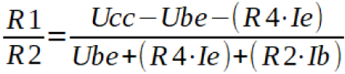
The below figure is the most widely used biasing configuration, it is temperature stable and provides very good gain and linearity. In RF amplifiers R3 can be replaced with an RF choke. In addition to a single base resistor (R1) and collector resistor (R3), we have an additional base resistor (R2) and an emitter resistor (R4). R1 and R2 form a voltage divider and along with the voltage drop on R4 set to the base voltage (Ub) of the circuit. The calculations are more complicated, due to there being more components and variables to account for.

First we start with calculating the resistor ratio of the base voltage divider, dictated by the formula shown below. To start the calculations we need to estimate the values of the collector current and resistors R2 & R4. Resistor R4 can be calculated to drop 0.5V to 2V at the desired collector current and R2 is set to be 10 to 20 times greater than R4. For preamplifiers R4 is usually in the range of 1k-2k ohm.
The non-decoupled R4 causes negative feedback, decreasing gain while decreasing distortion and improving linearity. Decoupling it with a capacitor increases gain so it is recommended to use a large value capacitor with a small resistor in series.
