
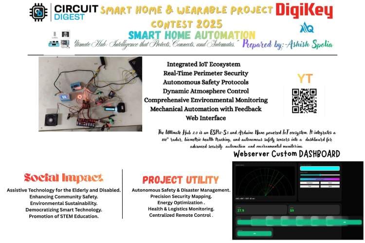
By Ashish Spolia
The rapid evolution of the Internet of Things (IoT) has transformed the modern household from a passive living space into an intelligent, responsive ecosystem. As safety concerns and the demand for convenience grow, there is a critical need for integrated systems that can monitor environmental hazards, provide robust security, and automate daily tasks seamlessly.
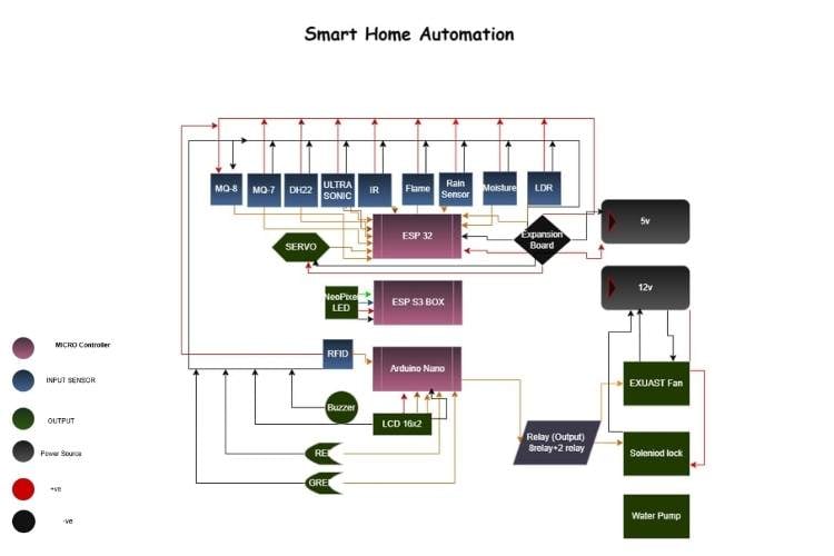
The Ultimate Hub 2.0 is designed to address these needs by bridging high-level wireless connectivity with complex hardware automation. This project utilizes a dual-controller architecture, employing an ESP32-S3-BOX-3 as the primary gateway for Wi-Fi and user interface management, alongside an Arduino Mega 2560 to handle a high density of sensors and actuators.
Core Objectives
The system is built upon four foundational pillars:
Autonomous Safety: Utilizing MQ-series gas sensors and flame detectors to provide real-time protection against fire and gas leaks through automated ventilation and alarms.
Advanced Perimeter Security: Implementing a 180° radar system and laser-based boundaries to visualize and detect intrusions.
Environmental Intelligence: Monitoring climate and lighting conditions via DHT22 and LDR sensors to optimize comfort and energy efficiency.
Centralized Control: Providing a professional, unified web dashboard for the manual and automated management of eight separate appliance channels.
Innovation & Impact
Unlike traditional smart home solutions that rely on fragmented apps, the Ultimate Hub 2.0 offers a consolidated command center. By integrating specialized features like a PRO LUX NeoPixel controller for atmosphere and a biometric heart-rate station, the project demonstrates how accessible, open-source hardware can be scaled into a professional-grade home management solution. This project not only enhances the quality of life but also serves as a robust model for future assistive technologies and industrial monitoring systems.
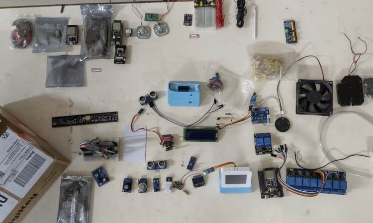
Components Required
| Component Name | Quantity | Datasheet/Link |
| Esp32 S3 Box 3 | 1 | View Datasheet |
| Arduino Nano /Mega | 1 | - |
| 16x2 lcd display | 1 | - |
| MQ-8 | 1 | - |
| MQ-7 | 1 | - |
| Flame | 1 | - |
| DH22 | 1 | - |
| Buzzer | 2 | - |
| Leds | 2 | - |
| Jumper wires | 40 | - |
| LDR | 2 | - |
| Laser | 1 | - |
| IR sensor | 3 | - |
| ULTRASONIC SENSOR | 1 | - |
| Servo | 1 | - |
| 8Relay module | 1 | - |
| 2Relay Module | 1 | - |
| Soil Moisture sensor | 1 | - |
| 5v water pump | 1 | - |
| Pir | 1 | - |
| LIMIT SWITCHES | 4 | - |
| Max30102 | 2 | - |
| Dc motor | 2 | - |
| Solenoid lock | 1 | - |
| Exaust fan | 1 | - |
| Breadboard | 2 | - |
| Esp32 dev v1 | 1 | - |
| Esp expansion board | 1 | - |
Circuit Diagram

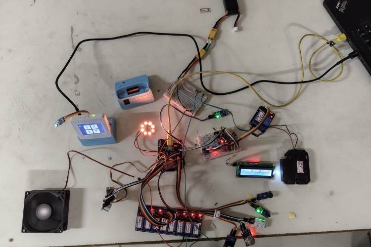
Hardware Assembly
Building this system requires careful attention to the power requirements and the specific pinout of the ESP32. Follow these steps to assemble your Ultimate Hub safely.

Phase 1: Power & Common Ground
The ESP32 generally runs on 3.3V, but your Relays and MQ sensors often need 5V to operate correctly.
Shared Power: Connect the VIN pin of the ESP32 to your 5V power source. Connect the GND pin to the negative terminal of your power source.
Common Ground: Ensure the ground (GND) of the Relay module, MQ sensors, and Servo are all connected back to the ESP32 GND. Without a shared ground, the signals will be "noisy" or won't work at all.
Phase 2: Connecting the Safety Sensors
The MQ sensors are analog, while the Flame sensor is digital.
MQ-7 (Carbon Monoxide): * VCC - 5V
GND - GND
AO (Analog Out) - GPIO 34
MQ-8 (Hydrogen/Smoke):
VCC- 5V
GND -GND
AO (Analog Out) - GPIO 35
Flame Sensor:
VCC -3.3V or 5V
GND -GND
DO (Digital Out) - GPIO 27
Buzzer:
Positive (+) -GPIO 25
Negative (-) - GND
Phase 3: Radar & Environmental Sensing
This involves the Servo, Ultrasonic sensor, and DHT22.
Servo Motor:
Red (VCC) - 5V
Brown/Black (GND) - GND
Yellow/Orange (Signal)-GPIO 18
Ultrasonic Sensor (HC-SR04):
VCC -5V
GND - GND
Trig - GPIO 5
Echo - GPIO 19 (Note: Use a voltage divider if you want to protect the 3.3V ESP32 pin from the 5V Echo signal).
DHT22 (Temp/Hum):
VCC- 3.3V
GND -GND
Data -GPIO 4
Phase 4: Lighting & Relays
NeoPixel Ring:
VCC - 5V (Connecting to 3.3V will result in dim/flickering lights).
GND - GND
Data In - GPIO 2
8-Channel Relay Module:
VCC - 5V
GND - GND
In1 to In8 GPIOs 13, 12, 14, 23, 22, 21, 33, 15 (respectively).
Note: Relay In2 (GPIO 12) is programmed as your Exhaust Fan.
Phase 5: Mechanical Mounting
The Radar: Use double-sided tape or a small bracket to mount the HC-SR04 Ultrasonic sensor onto the "horn" (the plastic arm) of the Servo motor. Ensure the wires have enough slack to spin 180 degrees without pulling out.
Air Flow: Place the MQ sensors and Flame sensor in an area where air can circulate. Do not hide them inside a sealed box, or they won't detect smoke/gas.
The Relay: High-voltage (AC) appliances should be connected to the "Normally Open" (NO) and "Common" (COM) terminals of the relay.
Safety Warning
If you are connecting real appliances (110V/220V AC) to the relay module, ensure the power is unplugged during assembly. Exposed high-voltage wires can be lethal. Use an insulated enclosure for the relay board.
Code Explanation
Below is the explanation of existing code After that I will provide you the explanation of that one which I will Do :-
This code turns an ESP32 into a sophisticated Smart Home Hub. It manages environmental sensing, safety automation, a radar system, and a professional web dashboard.Here is the step-by-step breakdown of how it works.
The Safety Logic (The "Brain")This is the part you specifically requested. It balances Automation with User Control.Continuous Monitoring: Inside loop(), the ESP32 constantly reads the MQ-7 (Carbon Monoxide), MQ-8 (Hydrogen/Smoke), and Flame sensors.The "Auto-On" Trigger: ```cppif ((gas7 > 2000 || gas8 > 2000 || flame) && relayStates[1] == false)If any hazard is detected **AND** the Exhaust (Relay 1) is currently OFF, the system forces it to turn ON.
User Manual Override: By using the relayStates[1] == false check, the system only sends the "Turn ON" command once when the hazard starts. If you click "OFF" on the website, it will stay off until the hazard is cleared and re-detected, or until the sensor values fluctuate.The Buzzer: Tied strictly to the flame variable. If there is a fire, it beeps; if the fire is out, it stops.The Radar System (Ultrasonic + Servo)This section creates a visual "sonar" on your webpage.The Sweep: The Servo moves the Ultrasonic sensor from 0° to 180° and back.Distance Calculation: It sends a sound pulse (trigPin) and measures how long it takes to bounce back (echoPin).Physics Formula: The distance is calculated using the speed of sound:$$Distance = \frac{Time \times 0.034}{2}$$Visualization: These coordinates (Angle and Distance) are sent to the web browser, where the JavaScript <canvas> draws the green radar lines and red "enemy" dots.
Professional Web Interface (The "Frontend")The large block of HTML/CSS/JavaScript in PAGE_HTML is stored in the ESP32's Flash Memory (PROGMEM).Dynamic Styling: It uses CSS variables (like --primary: #00ff41) to create a "Matrix/Cyberpunk" dark-mode look.JSON Data Exchange: Every 500ms, the website runs a fetch('/data') command. The ESP32 replies with a JSON string containing temperature, humidity, and relay states.Responsive Buttons: When you click a button, it sends a background request (e.g., /toggle?id=1) so the page doesn't have to reload.
NeoPixel Animation EngineThis handles the LED ring (connected to Pin 2).Non-Blocking Logic: Instead of using delay(), it uses millis() to check if it's time to update the next frame of the animation. This ensures the webserver doesn't freeze while the lights are flashing.Modes: It supports several modes:Rainbow (1): Randomized colors.Heart (11): Uses a math function pow(sin(patternStep * 0.1), 10) to create a smooth "breathing" red pulse.Bolt (20): Random white flashes to simulate lightning.
Hardware Configuration (The Pins)The code is designed for an 8-Channel Relay Module.Active-Low Logic: Most relay modules turn ON when the pin is LOW.Default State: In setup(), all pins are set to HIGH so your appliances don't all turn on the moment you plug in the power.
Now for the future prospects:-
Step 1: The Master-Slave Initialization
When you power on the system, both controllers boot up simultaneously.
The Mega (The Worker): It initializes the SPI bus for the RFID, attaches the Servo for the radar, and sets all 8 Relays to HIGH (which means OFF for active-low modules).
The ESP32 (The Gateway): It starts the WiFi station mode to connect to your "CMF" hotspot. Once connected, it launches the Asynchronous Web Server on Port 80, making the dashboard accessible via its IP address.
Step 2: The Radar Sweep Task
Inside the Mega's loop(), the Radar function is "non-blocking.
"The Mega moves the Servo by 2 degrees.
It triggers the Ultrasonic Sensor by sending a 10µs pulse to the TRIG pin.
It listens for the ECHO pulse. The time it takes for the sound to return is converted into centimeters (Distance = \frac{Time \times 0.034}{2}).This (Angle, Distance)$l pair is stored in memory, ready to be sent to the dashboard.
Step 3: Autonomous Safety Monitoring
This is the most critical part of the code. The Mega does not wait for a command to save the house.
Gas/Smoke: It reads the analog values from MQ-7 and MQ-8. If the value crosses 2000, it immediately sets Relay 1 (Exhaust) to LOW (ON).
Fire: It checks the Flame Sensor. If a fire is detected, it overrides everything to turn on the Buzzer and the Exhaust Fan.
Logic: This happens locally on the Mega, so even if the WiFi goes down, your house remains protected.
Step 4: Atmospheric & Status Packaging
Every 500ms, the Mega packages all its data into a JSON string.
Example String: {"t":25.4, "h":60, "ang":90, "dst":45, "alrm":0}
It sends this string over the Serial1 (TX1/RX1) lines to the ESP32. This keeps the "Brain" updated on what the "Body" is sensing.
Step 5: The Webserver & Fetch Logic
On the user's side (phone or laptop):
The browser loads the PAGE_HTML stored in the ESP32's flash memory.
A JavaScript function called update() runs every second.
It "fetches" the latest JSON data from the /status route on the ESP32.
The script then dynamically updates the Radar Canvas and the Temperature/Humidity text without refreshing the whole page.
Step 6: Command Execution (Relay Toggling)
When you click a "TOGGLE" button on your dashboard:
The browser sends a request to /toggle?id=3 (for example, to turn on the Light).
The ESP32 receives this request and immediately sends a short command TGL3 through Serial to the Mega.
The Mega receives TGL3, performs a digitalWrite(relayPins[3], !digitalRead(relayPins[3])), and the physical light turns on.
Summary of Logic Flow
Sensors -> Mega: Constant scanning.
Mega ->ESP32: Updates the status via Serial.
ESP32 -> Browser: Displays the data on the Glassmorphism UI.
User -> ESP32 ->Mega: Sends the command to flip a relay..
GitHub Repository


