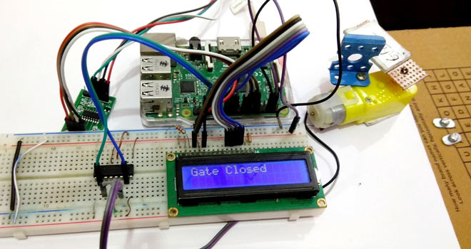
In this project we are going to use Load cell and HX711 Weight Sensor with Raspberry Pi to build a Automatic Gate. We have seen these pressure sensing gates at many malls and showrooms, which automatically opens when someone is standing near the door and get closed after that person is gone. So here we are also creating the same Automatic Gate which will sense the pressure and get opened automatically and will remain open until that pressure or weight will be there. This gate will be closed automatically as soon as the weight is removed. This automatic gate can also be built using PIR sensor like here.
Here for demonstration purpose, we have used simple DC motor as the gate and a hard cardboard as a platform for putting the weight, check the demo Video at the end. In last tutorial, we have Interfaced Load Cell and HX711 with Arduino to measure the weights. For more Raspberry Projects, check here.
Required Components:
- Raspberry Pi (any model should work)
- Load cell
- HX711 Load cell Amplifier Module
- L293D Motor Driver IC
- DC motor or Electric gate or DVD trolley
- 16x2 LCD
- Power source or power bank
- Connecting wires
- Breadboard
- Nut bolts, Frame and base
Load Cell and HX711 Weight Sensor Module:
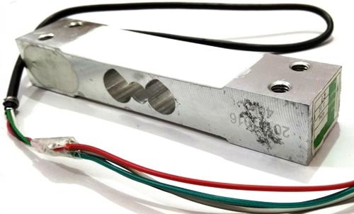
Load cell is transducer which transforms force or pressure into electrical output. Magnitude of this electrical output is directly proportion to the force being applied. Load cells have strain gauge, which deforms when pressure is applied on it. And then strain gauge generates electrical signal on deformation as its effective resistance changes on deformation. A load cell usually consists of four strain gauges in a Wheatstone bridge configuration. Load cell comes in various ranges like 5kg, 10kg, 100kg and more, here we have used Load cell, which can weight upto 40kg.
Now the electrical signals generated by Load cell is in few millivolts, so they need to be further amplify by some amplifier and hence HX711 Weighing Sensor comes into picture. HX711 Weighing Sensor Module has HX711 chip, which is a 24 high precision A/D converter (Analog to digital converter). HX711 has two analog input channels and we can get gain up to128 by programming these channels. So HX711 module amplifies the low electric output of Load cells and then this amplified & digitally converted signal is fed into the Arduino to derive the weight.
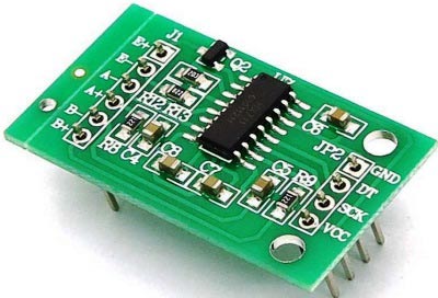
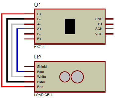
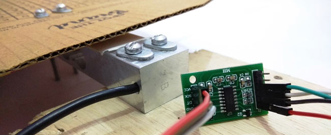
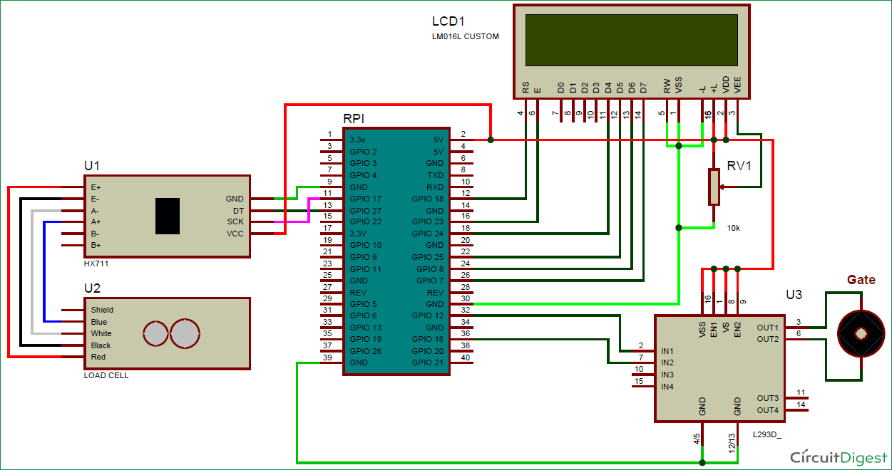
Load cell is connected with HX711 Load cell Amplifier using four wires. These four wires are Red, Black, White and Green/Blue. There may be slight variation in colors of wires from module to module. Below the connection details and diagram:
- RED Wire is connected to E+
- BLACK Wire is connected to E-
- WHITE Wire is connected to A-
- GREEN/BLUE Wire is connected to A+
Fixing Load Cell with Platform and Base:
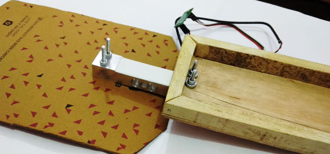
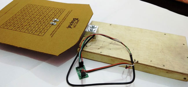
In order to make this whole setup work, we have to install Load Cell under the ground in front of the door, so that it can sense the weight of person standing near the door. But here for Demonstration purpose, we have fixed the Load cell under a hard cardboard, which will serve as a platform where we can put the weight and can test the gate. Load cell has also been fixed with Wooden Base with the help of nuts and bolts, so that it will remain still. Below are some pictures of the setup:
Circuit Explanation:
Connections for this Automatic Gate project are easy and schematic is given below. 16x2 LCD pins RS, EN, d4, d5, d6, and d7 are connected with GPIO pin number 18, 23, 24, 25, 8 and 7 of Raspberry Pi respectively. HX711 Module’s DT and SCK pins are directly connected with Raspberry Pi's GPIO pin 27 and 17 and Motor Driver L293D is connected at GPIO pin 12 and 16 of Raspberry Pi. Load cell connections with HX711 module are already explained earlier and also shown in the below circuit diagram.
Working Explanation:
In this project, we have used Raspberry Pi 3 to control whole the process. Load cell senses the Pressure on the floor near the gate and supplies a electrical analog voltage to HX711 Load Amplifier Module. HX711 is a 24bit ADC, which amplifies and converts the Load cell output into digital form. Then this amplified value is fed to the Raspberry Pi. Now Raspberry Pi calculates the output of HX711 and converts that into the weight value. Then Raspberry Pi compares the value with reference weight and drives the gate accordingly by using motor driver IC L293D. Here we have used DC motor for demonstrate it as gate. If you want to use DVD Trolley as a gate then check our previous tutorial: Automatic Door Opener using Arduino
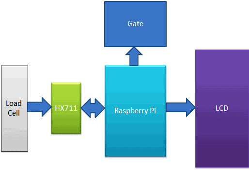
Here we have used Reference weight of 100 gram, means if someone greater than 100gm will be standing there near the door, then only gate will be opened. And the gate will closed when we remove that 100gm or the person is gone. You can change the reference weight accordingly. An optional 16x2 LCD is used for displaying gate status. We have written a Python program for whole process, check the Python Code and demo Video at the end of this tutorial.
Programming Explanation:
Here we have used Python for the Programming. In this project, we did not use any library for interfacing HX711 load sensor with Raspberry Pi. We have just followed the datasheet of HX711 and application notes. Although there are some libraries present for this purpose, where you only need to include that library and you can get the weight using few lines of code.
First of all, we have included Library for GPIO pins and defined pins for LCD, HX711 and DC motor, also declared some variables for calculation purpose.
import RPi.GPIO as gpio
import time

RS =18
EN =23
D4 =24
D5 =25
D6 =8
D7 =7

DT =27
SCK=17

m1=12
m2=1
After it, we have created below function for reading data from HX711 module and return its output.
def readCount():
  i=0
  Count=0
  gpio.setup(DT, gpio.OUT)
  gpio.output(DT,1)
  gpio.output(SCK,0)
  gpio.setup(DT, gpio.IN)

  while gpio.input(DT) == 1:
      i=0
  for i in range(24):
        gpio.output(SCK,1)
        Count=Count<<1

        gpio.output(SCK,0)
        #time.sleep(0.001)
        if gpio.input(DT) == 0:
            Count=Count+1

  gpio.output(SCK,1)
  Count=Count^0x800000
  gpio.output(SCK,0)
  return Count
New in main function, we read data from HX711 module and compare it with reference weight and take actions to open or close the gate accordingly.
while 1:
  count= readCount()
  w=0
  w=(count-sample)/106
  print w,"g"
  if w>100:
    setCursor(0,0)
    lcdprint("Gate Opened ")
    if flag == 0:
      gpio.output(m1, 1)
      gpio.output(m2, 0)
      time.sleep(1.3)
      gpio.output(m1, 0)
      gpio.output(m2, 0)
      time.sleep(1.5)
      flag=1;
      lcdclear()
  elif w<100:
    setCursor(0,0)
    lcdprint("Gate Closed ")
    if flag==1:
      gpio.output(m1, 0)
      gpio.output(m2, 1)
      time.sleep(1.3)
      gpio.output(m1, 0)
      gpio.output(m2, 0)
      time.sleep(2)
      flag=0
  time.sleep(0.5)
Some functions are also created for LCD, like def begin(): for initialize the LCD, def lcdcmd(ch): for sending commands to LCD, def lcdwrite(ch): for printing character on LCD, def lcdclear(): for clearing the LCD and def lcdprint(Str): for printing the string. Check all the functions in the Full code given below.
So here we have seen that we can easily create this Weight sensing Automatic Gate using Raspberry Pi and Load cell.
Complete Project Code
import RPi.GPIO as gpio

import time
RS =18

EN =23

D4 =24

D5 =25

D6 =8

D7 =7
DT =27

SCK=17
m1=12

m2=16
HIGH=1

LOW=0
sample=0

val=0
gpio.setwarnings(False)

gpio.setmode(gpio.BCM)

gpio.setup(RS, gpio.OUT)

gpio.setup(EN, gpio.OUT)

gpio.setup(D4, gpio.OUT)

gpio.setup(D5, gpio.OUT)

gpio.setup(D6, gpio.OUT)

gpio.setup(D7, gpio.OUT)

gpio.setup(m1, gpio.OUT)

gpio.setup(m2, gpio.OUT)

gpio.setup(SCK, gpio.OUT)

gpio.output(m1 , 0)

gpio.output(m2 , 0)

def begin():

  lcdcmd(0x33)

  lcdcmd(0x32)

  lcdcmd(0x06)

  lcdcmd(0x0C)

  lcdcmd(0x28)

  lcdcmd(0x01)

  time.sleep(0.0005)


def lcdcmd(ch):

  gpio.output(RS, 0)

  gpio.output(D4, 0)

  gpio.output(D5, 0)

  gpio.output(D6, 0)

  gpio.output(D7, 0)

  if ch&0x10==0x10:

    gpio.output(D4, 1)

  if ch&0x20==0x20:

    gpio.output(D5, 1)

  if ch&0x40==0x40:

    gpio.output(D6, 1)

  if ch&0x80==0x80:

    gpio.output(D7, 1)

  gpio.output(EN, 1)

  time.sleep(0.005)

  gpio.output(EN, 0)
  # Low bits

  gpio.output(D4, 0)

  gpio.output(D5, 0)

  gpio.output(D6, 0)

  gpio.output(D7, 0)

  if ch&0x01==0x01:

    gpio.output(D4, 1)

  if ch&0x02==0x02:

    gpio.output(D5, 1)

  if ch&0x04==0x04:

    gpio.output(D6, 1)

  if ch&0x08==0x08:

    gpio.output(D7, 1)

  gpio.output(EN, 1)

  time.sleep(0.005)

  gpio.output(EN, 0)


def lcdwrite(ch):

  gpio.output(RS, 1)

  gpio.output(D4, 0)

  gpio.output(D5, 0)

  gpio.output(D6, 0)

  gpio.output(D7, 0)

  if ch&0x10==0x10:

    gpio.output(D4, 1)

  if ch&0x20==0x20:

    gpio.output(D5, 1)

  if ch&0x40==0x40:

    gpio.output(D6, 1)

  if ch&0x80==0x80:

    gpio.output(D7, 1)

  gpio.output(EN, 1)

  time.sleep(0.005)

  gpio.output(EN, 0)
  # Low bits

  gpio.output(D4, 0)

  gpio.output(D5, 0)

  gpio.output(D6, 0)

  gpio.output(D7, 0)

  if ch&0x01==0x01:

    gpio.output(D4, 1)

  if ch&0x02==0x02:

    gpio.output(D5, 1)

  if ch&0x04==0x04:

    gpio.output(D6, 1)

  if ch&0x08==0x08:

    gpio.output(D7, 1)

  gpio.output(EN, 1)

  time.sleep(0.005)

  gpio.output(EN, 0)
def lcdclear():

  lcdcmd(0x01)


def lcdprint(Str):

  l=0;

  l=len(Str)

  for i in range(l):

    lcdwrite(ord(Str[i]))


def setCursor(x,y):

    if y == 0:

        n=128+x

    elif y == 1:

        n=192+x

    lcdcmd(n)
def readCount():

  i=0

  Count=0

 # print Count

 # time.sleep(0.001)

  gpio.setup(DT, gpio.OUT)

  gpio.output(DT,1)

  gpio.output(SCK,0)

  gpio.setup(DT, gpio.IN)
  while gpio.input(DT) == 1:

      i=0

  for i in range(24):

        gpio.output(SCK,1)

        Count=Count<<1
        gpio.output(SCK,0)

        #time.sleep(0.001)

        if gpio.input(DT) == 0:

            Count=Count+1

            #print Count


  gpio.output(SCK,1)

  Count=Count^0x800000

  #time.sleep(0.001)

  gpio.output(SCK,0)

  return Count
begin()

lcdcmd(0x01)

lcdprint(" Automatic Gate ")

lcdcmd(0xc0)

lcdprint("    Using RPI   ")

time.sleep(3)

lcdcmd(0x01)

lcdprint("Circuit Digest")

lcdcmd(0xc0)

lcdprint("Welcomes You")

time.sleep(3)

sample= readCount()

flag=0

lcdclear()

while 1:

  count= readCount()

  w=0

  w=(count-sample)/106

  print w,"g"

  if w>100:

    setCursor(0,0)

    lcdprint("Gate Opened ")

    if flag == 0:

      gpio.output(m1, 1)

      gpio.output(m2, 0)

      time.sleep(1.3)

      gpio.output(m1, 0)

      gpio.output(m2, 0)

      time.sleep(1.5)

      flag=1;

      lcdclear()

  elif w<100:

    setCursor(0,0)

    lcdprint("Gate Closed ")

    if flag==1:

      gpio.output(m1, 0)

      gpio.output(m2, 1)

      time.sleep(1.3)

      gpio.output(m1, 0)

      gpio.output(m2, 0)

      time.sleep(2)

      flag=0

  time.sleep(0.5)
Comments
i need code in arduino with motor on off
What is the sample value in main function???
could you provide a schematic using a i2c LCD display instead?
I need Full details of the programming code where should be written.



I am trying to put this together but am struggling with the Diagram , specifically the LCD connection,
I wont be using a breadboard for this so was hoping you could show me how the wires that are connected to the 10k resistor should be connected?
thanks for your help x
Abby