

We all know that Raspberry Pi is a wonderful Development platform based on ARM microprocessor. With its high computational power it can work out wonders in hands of electronics hobbyists or students. All this can be possible only if we know how to make it interact with the real world and analyse the data through some output device. There are many sensors which can detect certain parameters from the real time world and transfer it to a digital world and we analyse them viewing them either in a LCD screen or some other display. But, it would always be not economical to use a LCD screen with PI for displaying small amount of data. This is where we prefer to use 16x2 Alphanumeric LCD display or the 7-Segment display. We have already learnt how to use a Alphanumeric LCD and a single segment 7-segment display with Raspberry pi. Today we will Interface 4-digit Seven Segment Display Module with Raspberry Pi and display Time over it.
Although 16x2 Alphanumeric LCD is much more comfortable than 7-segment display, there are few scenarios where a 7-segment display would come in handier than a LCD display. LCD suffers from the drawback of having low character size and will be overkill for your project if you are just planning to display some numeric values. 7-segments also have the advantage against poor lighting condition and can be viewed from lager angles than a normal LCD screen. So, let us start knowing it.
7-Segment and 4-Digit 7-Segment Display Module:
7 Segment Display has seven segments in it and each segment has one LED inside it to display the numbers by lighting up the corresponding segments. Like if you want the 7-segment to display the number "5" then you need to glow segment a,f,g,c, and d by making their corresponding pins high. There are two types of 7-segment displays: Common Cathode and Common Anode, here we are using Common Cathode seven segment display. Learn more about 7 segment display here.
Now we know how to display our desired numeric character on a single 7-segment display. But, it is pretty evident that we would need more than one 7-segment display to convey any information that is more than one digit. So, in this tutorial we will be using a 4-digit 7-Segment Display Module as shown below.
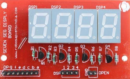
As we can see there are Four Seven Segment Displays connected together. We know that each 7-segment module will have 10 pins and for 4 seven segment displays there would be 40 pins in total and it would be hectic for anyone to solder them on a dot board, so I would highly recommend anyone to buy a module or make your own PCB for using a 4-digit 7-segment display. The connection schematic for the same is shown below:
To understand how 4-digit seven segment module works we have to look into the above schematics, as shown the A pins of all four display is connected to gather as one A and the same for B,C.... upto DP. So, basically if trigger A on, then all four A's should go high right?
But, that does not happen. We have additional four pins from D0 to D3 (D0, D1, D2 and D3) which can be used to control which display out of the four should go high. For example: If I need my output to be present only on the second display then only D1 should be made high while keeping other pins (D0, D2, and D3) as low. Simply we can select which display has to go active using the pins from D0 to D3 and what character to be display using the pins from A to DP.
Connecting 4-digit 7-segment module with Raspberry Pi:
Let us see how, how we can connect this 4-digit 7-segment module with our Raspberry Pi. The 7-segment module has 16 pins as shown below. You module might have lesser, but don’t worry it will still have the following for sure
- 7 or 8 segment pins (here pins starting from 1 to 8)
- Ground pin (here pin 11)
- 4 digit pins (here pins 13 to 16)
Below given is the schematic for raspberry pi digital clock by connecting 4-digit Seven segment display module with Raspberry Pi:

The following table will also help you in making the connections and verifying it to be as per the schematics shown above.
|
S.No |
Rsp Pi GPIO number |
Rsp Pi PIN number |
7-Segment name |
7-Seg pin number (here in this module) |
|
1 |
GPIO 26 |
PIN 37 |
Segment a |
1 |
|
2 |
GPIO 19 |
PIN 35 |
Segment b |
2 |
|
3 |
GPIO 13 |
PIN 33 |
Segment c |
3 |
|
4 |
GPIO 6 |
PIN 31 |
Segment d |
4 |
|
5 |
GPIO 5 |
PIN 29 |
Segment e |
5 |
|
6 |
GPIO 11 |
PIN 23 |
Segment f |
6 |
|
7 |
GPIO 9 |
PIN 21 |
Segment g |
7 |
|
8 |
GPIO 10 |
PIN 19 |
Segment DP |
8 |
|
9 |
GPIO 7 |
PIN 26 |
Digit 1 |
13 |
|
10 |
GPIO 8 |
PIN 24 |
Digit 2 |
14 |
|
11 |
GPIO 25 |
PIN 22 |
Digit 3 |
15 |
|
12 |
GPIO 24 |
PIN 18 |
Digit 4 |
16 |
|
13 |
Ground |
Ground |
Ground |
11 |
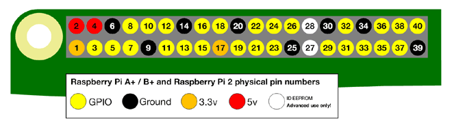
Identify the pins on your module and you are all good to proceed with the connections. Spotting the GPIO pins in Raspberry pi might be a bit challenging task so I have provided you this picture for GPIO Pins.
Programming your Raspberry Pi:
Here we are using Python Programming language for programming RPi. There are many ways to program your Raspberry Pi. In this tutorial we are using the Python 3 IDE, since it is the most used one. The complete Python program is given at the end of this tutorial. Learn more about Program and run code in Raspberry Pi here.
We will talk about few commands which we are going to use in PYHTON program for this project,
First we are going to import GPIO file from library, below function enables us to program GPIO pins of PI. We are also renaming “GPIO” to “IO”, so in the program whenever we want to refer to GPIO pins we will use the word ‘IO’. We have also imported time and datetime to read the value of time from Rsp Pi.
import RPi.GPIO as GPIO
import time, datetime
Sometimes, when the GPIO pins, which we are trying to use, might be doing some other functions. In that case, we will receive warnings while executing the program. Below command tells the PI to ignore the warnings and proceed with the program.
IO.setwarnings(False)
We can refer the GPIO pins of PI, either by pin number on board or by their function number. Like ‘PIN 29’ on the board is ‘GPIO5’. So we tell here either we are going to represent the pin here by ‘29’ or ‘5’. GPIO.BCM means we will represent using 5 for GPIO5 pin 29.
IO.setmode (GPIO.BCM)
As always we should begin by initialising the pins, here both the segment pins and the digit pins are output pins. For programming purpose we form arrays for segment pins and initialize them to ‘0’ after declaring them as GPIO.OUT
segment8 = (26,19,13,6,5,11,9,10)
for segment in segment8:
    GPIO.setup(segment, GPIO.OUT)
    GPIO.output(segment, 0)
Similarly for the digit pins we declare them as output pins and make them ‘0’ by default
    #Digit 1
    GPIO.setup(7, GPIO.OUT)
    GPIO.output(7, 0) #Off initially
    #Digit 2
    GPIO.setup(8, GPIO.OUT)
    GPIO.output(8, 0) #Off initially
    #Digit 3
    GPIO.setup(25, GPIO.OUT)
    GPIO.output(25, 0) #Off initially
    #Digit 4
    GPIO.setup(24, GPIO.OUT)
    GPIO.output(24, 0) #Off initially
We have to form arrays to display each number on a seven segment display. To display one number we have to control all 7 segment pins (dot pin excluded), that is they either has to be turned off or turned on. For example to display the number 5 we have make the following arrangement
|
S.No |
Rsp Pi GPIO number |
7-Segment name |
Status to display ‘5’. (0-> OFF, 1->ON) |
|
1 |
GPIO 26 |
Segment a |
1 |
|
2 |
GPIO 19 |
Segment b |
1 |
|
3 |
GPIO 13 |
Segment c |
0 |
|
4 |
GPIO 6 |
Segment d |
1 |
|
5 |
GPIO 5 |
Segment e |
1 |
|
6 |
GPIO 11 |
Segment f |
0 |
|
7 |
GPIO 9 |
Segment g |
1 |
Similarly we have sequence number for all numbers and alphabets. You can write on your own or use the chart below.
With these data we can form the arrays for each number in our python program as shown below.
null = [0,0,0,0,0,0,0]
zero = [1,1,1,1,1,1,0]
one = [0,1,1,0,0,0,0]
two = [1,1,0,1,1,0,1]
three = [1,1,1,1,0,0,1]
four = [0,1,1,0,0,1,1]
five = [1,0,1,1,0,1,1]
six = [1,0,1,1,1,1,1]
seven = [1,1,1,0,0,0,0]
eight = [1,1,1,1,1,1,1]
nine = [1,1,1,1,0,1,1]
If you follow the program there will be a function to display each character to our 7-segment display but, lets skip this for now and get into the while infinite loop. Where read the present time from Raspberry Pi and split the value of time between four variables. For example if the time is 10.45 then the variable h1 will have 1, h2 will have 0, m1 will have 4vand m2 will have 5.
    now = datetime.datetime.now()
    hour = now.hour
    minute = now.minute
    h1 = hour/10
    h2 = hour % 10
    m1 = minute /10
    m2 = minute % 10
    print (h1,h2,m1,m2)
We have to display these four variable values on our four digits respectively. To write a value of variable to a digit we can use the following lines. Here we are display on digit 1 by making it go high then the function print_segment (variable) will be called to display the value in variable on the segment display. You might be wondering why we have a delay after that and why we turn this digit off after this.
GPIO.output(7, 1) #Turn on Digit One
print_segment (h1) #Print h1 on segment
time.sleep(delay_time)
GPIO.output(7, 0) #Turn off Digit One
The reason is, as we know we can display only one digit at a time, but we have four digits to be displayed and only if all the four digits are displayed the complete four digit number will be visible for the user.
So, how do display all 4 digits at the same time?
Lucky for us our MPU is very much faster than a human eye, so what we actually do: we display one digit at a time but we do it very fast as shown above.
We select one digit display it wait for 2ms (variable delay_time) so that the MPU and 7-segment can process it and then turn off that digit and move on to the next digit and do the same till we reach the last digit. This delay of 2ms cannot be observed by a human eye and all the four digits appear to be ON at the same time.
The last thing to learn it to know how the print_segment(variable) function works. Inside this function we use the arrays that we have declared so far. So whatever variable that we send to this function should have the value between (0-9), the variable character will receive this value and compare it for real value. Here the variable is compared with ‘1’. Similarly we compare with all number from 0 to 9. If it is a match we use the arrays and assign each value to its respective segment pins as shown below.
def print_segment(charector):
    if charector == 1:
        for i in range(7):
            GPIO.output(segment8[i], one[i])
Display time on 4-Digit 7-segment using Raspberry Pi:
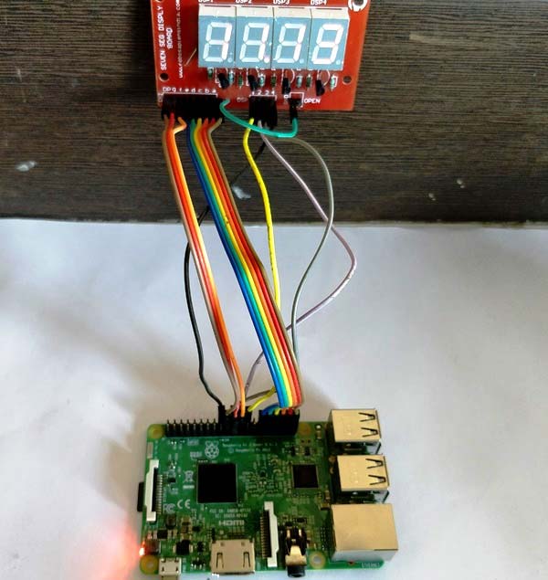
Use the schematic and code given here to make the connections and program your raspberry pi accordingly. After everything is done just launch the program and you should find the current time being displayed in the seven segment display. But, there are few things that you have to check before this
- Make sure you have set your Raspberry Pi with current time just in case if it running on offline time.
- Power your Raspberry pi with a Adapter and not with your Laptop/computer because the amount of current drawn by the 7-segment display is high and your USB port cannot source it.
If everything is working as expected, then you should find something like this below.
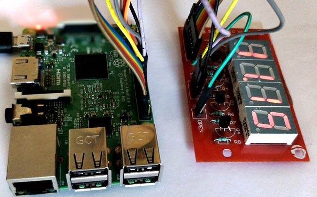
The complete working of this raspberry pi clock can also be checked at the video given below. Hope you liked the project and enjoyed building one. Let me know what you think or if you need help.
Complete Project Code
import RPi.GPIO as GPIO

import time, datetime
now = datetime.datetime.now()
GPIO.setmode(GPIO.BCM)

GPIO.setwarnings(False)


 #GPIO ports for the 7seg pins

segment8 =  (26,19,13,6,5,11,9,10)


for segment in segment8:

    GPIO.setup(segment, GPIO.OUT)

    GPIO.output(segment, 0)


    #Digit 1

    GPIO.setup(7, GPIO.OUT)

    GPIO.output(7, 0) #Off initially

    #Digit 2

    GPIO.setup(8, GPIO.OUT)

    GPIO.output(8, 0) #Off initially

    #Digit 3

    GPIO.setup(25, GPIO.OUT)

    GPIO.output(25, 0) #Off initially

    #Digit 4

    GPIO.setup(24, GPIO.OUT)

    GPIO.output(24, 0) #Off initially

null = [0,0,0,0,0,0,0]

zero = [1,1,1,1,1,1,0]

one = [0,1,1,0,0,0,0]

two = [1,1,0,1,1,0,1]

three = [1,1,1,1,0,0,1]

four = [0,1,1,0,0,1,1]

five = [1,0,1,1,0,1,1]

six = [1,0,1,1,1,1,1]

seven = [1,1,1,0,0,0,0]

eight = [1,1,1,1,1,1,1]

nine = [1,1,1,1,0,1,1]

def print_segment(charector):

    if charector == 1:

        for i in range(7):

            GPIO.output(segment8[i], one[i])
    if charector == 2:

        for i in range(7):

            GPIO.output(segment8[i], two[i])
    if charector == 3:

        for i in range(7):

            GPIO.output(segment8[i], three[i])
    if charector == 4:

        for i in range(7):

            GPIO.output(segment8[i], four[i])
    if charector == 5:

        for i in range(7):

            GPIO.output(segment8[i], five[i])
    if charector == 6:

        for i in range(7):

            GPIO.output(segment8[i], six[i])
    if charector == 7:

        for i in range(7):

            GPIO.output(segment8[i], seven[i])
    if charector == 8:

        for i in range(7):

            GPIO.output(segment8[i], eight[i])
    if charector == 9:

        for i in range(7):

            GPIO.output(segment8[i], nine[i])
    if charector == 0:

        for i in range(7):

            GPIO.output(segment8[i], zero[i])


    return;
while 1:
    now = datetime.datetime.now()

    hour = now.hour

    minute = now.minute

    h1 = hour/10

    h2 = hour % 10

    m1 = minute /10

    m2 = minute % 10

    print (h1,h2,m1,m2)


    delay_time = 0.001 #delay to create virtual effect


    GPIO.output(7, 1) #Turn on Digit One

    print_segment (h1) #Print h1 on segment

    time.sleep(delay_time)

    GPIO.output(7, 0) #Turn off Digit One
    GPIO.output(8, 1) #Turn on Digit One

    print_segment (h2) #Print h1 on segment

    GPIO.output(10, 1) #Display point On

    time.sleep(delay_time)

    GPIO.output(10, 0) #Display point Off

    GPIO.output(8, 0) #Turn off Digit One
    GPIO.output(25, 1) #Turn on Digit One

    print_segment (m1) #Print h1 on segment

    time.sleep(delay_time)

    GPIO.output(25, 0) #Turn off Digit One
    GPIO.output(24, 1) #Turn on Digit One

    print_segment (m2) #Print h1 on segment

    time.sleep(delay_time)

    GPIO.output(24, 0) #Turn off Digit One


    #time.sleep(1)

How is this circuit possible if the Raspberry pi does not have an onboard real time clock?