
One of the coolest embedded platforms like the Arduino has given makers and DIYers the ability to get location data easily using GPS module and thus build things that rely on location. With the amount of power packed by the Raspberry Pi, it certainly will be quite awesome to build GPS based projects with the same cheap GPS modules and that is the focus of this post. Today in this project we will Interface GPS module with Raspberry Pi 3.
The goal of this project is to collect location data (longitude and latitude) via UART from a GPS module and display them on a 16x2 LCD, so if you are not familiar with the way the 16x2 LCD works with the Raspberry Pi, this is another great opportunity to learn.
Required Components:
- Raspberry Pi 3
- Neo 6m v2 GPS Module
- 16 x 2 LCD
- Power source for the Raspberry Pi
- LAN cable to connect the pi to your PC in headless mode
- Breadboard and Jumper cables
- Resistor / potentiometer to the LCD
- Memory card 8 or 16Gb running Raspbian Jessie
Other than that we need to install GPS Daemon (GPSD) library, 16x2 LCD Adafruit library, which we install later in this tutorial.
Here we are using Raspberry Pi 3 with Raspbian Jessie OS. All the basic Hardware and Software requirements are previously discussed, you can look it up in the Raspberry Pi Introduction.
GPS Module and Its Working:
GPS stands for Global Positioning System and used to detect the Latitude and Longitude of any location on the Earth, with exact UTC time (Universal Time Coordinated). GPS module is the main component in our vehicle tracking system project. This device receives the coordinates from the satellite for each and every second, with time and date.
GPS module sends the data related to tracking position in real time, and it sends so many data in NMEA format (see the screenshot below). NMEA format consist several sentences, in which we only need one sentence. This sentence starts from $GPGGA and contains the coordinates, time and other useful information. This GPGGA is referred to Global Positioning System Fix Data. Know more about Reading GPS data and its strings here.
We can extract coordinate from $GPGGA string by counting the commas in the string. Suppose you find $GPGGA string and stores it in an array, then Latitude can be found after two commas and Longitude can be found after four commas. Now these latitude and longitude can be put in other arrays.
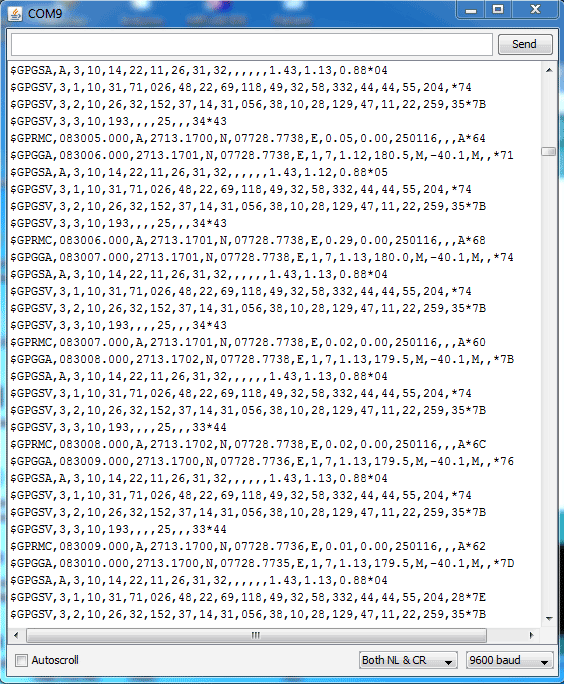
Below is the $GPGGA String, along with its description:
$GPGGA,104534.000,7791.0381,N,06727.4434,E,1,08,0.9,510.4,M,43.9,M,,*47
$GPGGA,HHMMSS.SSS,latitude,N,longitude,E,FQ,NOS,HDP,altitude,M,height,M,,checksum data
|
Identifier |
Description |
|
$GPGGA |
Global Positioning system fix data |
|
HHMMSS.SSS |
Time in hour minute seconds and milliseconds format. |
|
Latitude |
Latitude (Coordinate) |
|
N |
Direction N=North, S=South |
|
Longitude |
Longitude(Coordinate) |
|
E |
Direction E= East, W=West |
|
FQ |
Fix Quality Data |
|
NOS |
No. of Satellites being Used |
|
HPD |
Horizontal Dilution of Precision |
|
Altitude |
Altitude from sea level |
|
M |
Meter |
|
Height |
Height |
|
Checksum |
Checksum Data |
You can check our other GPS projects:
- Arduino based Vehicle Tracker using GPS and GSM
- Arduino Based Vehicle Accident Alert System using GPS, GSM and Accelerometer
- How to Use GPS with Arduino
- Track A Vehicle on Google Maps using Arduino, ESP8266 & GPS
Preparing the Raspberry Pi to communicate with GPS:
Okay so to jump in, so this doesn’t get boring, I will assume you already know a lot about the Raspberry Pi, enough to get your OS installed, obtain the IP address, connect to terminal software like putty and other things about the PI. Should you have any issue doing any of the things mentioned above, hit me up under the comment section and I will be glad to help.
The first thing we have to do to get this project underway is to prepare our Raspberry Pi 3 to be able to communicate with the GPS module via UART, believe me, its quite tricky and took quite the try to get it right but if you follow my guide carefully you will get it at one go, this is fairly the most difficult part of the project. Here we have used Neo 6m v2 GPS Module.
To dive in, here’s a little explanation of How the Raspberry Pi 3 UART Works.
The Raspberry Pi has two built-in UARTs, a PL011 and a mini UART. They are implemented using different hardware blocks so they have slightly different characteristics. On the raspberry pi 3 however, the wireless/bluetooth module is connected to the PLO11 UART, while the mini UART is used for the linux console ouptut. Depending on how you see it, I will define the PLO11 as the best of the two UART due to its implementation level. So for this project we will be deactivating the Bluetooth module from the PLO11 UART using an overlay available in the updated current version of the Raspbian Jessie.
Step 1: Updating the Raspberry Pi:
The first thing I like I like to do before starting every project is updating the raspberry pi. So lets do the usual and run the commands below;
sudo apt-get update
sudo apt-get upgrade
then reboot the system with;
sudo reboot
Step 2: Setting up the UART in Raspberry Pi:
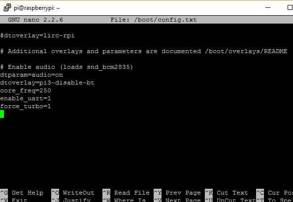
The first thing we will do under this is to edit the /boot/config.txt file. To do this, run the commands below:
sudo nano /boot/config.txt
at the bottom of the config.txt file, add the following lines
dtparam=spi=on
dtoverlay=pi3-disable-bt
core_freq=250
enable_uart=1
force_turbo=1
ctrl+x to exit and press y and enter to save.
Ensure there are no typos or errors by double checking as an error with this might prevent your pi from booting.
What are the reasons for these commands, force_turbo enables UART to use the maximum core frequency which we are setting in this case to be 250. The reason for this is to ensure consistency and integrity of the serial data been received. Its important to note at this point that using force_turbo=1 will void the warranty of your raspberry pi, but asides that, its pretty safe.
The dtoverlay=pi3-disable-bt disconnects the bluetooth from the ttyAMA0, this is to allow us access to use the full UART power available via ttyAMAO instead of the mini UART ttyS0.
Second step under this UART setup section is to edit the boot/cmdline.txt
I will suggest you make a copy of the cmdline.txt and save first before editing so you can revert back to it later if needed. This can be done using;
sudo cp boot/cmdline.txt boot/cmdline_backup.txt
sudo nano /boot.cmdline.txt
Replace the content with;
dwc_otg.lpm_enable=0 console=tty1 root=/dev/mmcblk0p2 rootfstype=ext4 elevator=deadline fsck.repair=yes rootwait quiet splash plymouth.ignore-serial-consoles
Save and exit.
With this done then we will need to reboot the system again to effect changes (sudo reboot).
Step3: Disabling the Raspberry Pi Serial Getty Service
The next step is to disable the Pi’s serial the getty service, the command will prevent it from starting again at reboot:
sudo systemctl stop serial-getty@ttyS0.service
sudo systemctl disable serial-getty@ttyS0.service
The following commands can be used to enable it again if needed
sudo systemctl enable serial-getty@ttyS0.service
sudo systemctl start serial-getty@ttyS0.service
Reboot the system.
Step 4: Activating ttyAMAO:
We have disabled the ttyS0, next thing is for us to enable the ttyAMAO.
sudo systemctl enable serial-getty@ttyAMA0.service
Step5: Install Minicom and pynmea2:
We will be minicom to connect to the GPS module and make sense of the data. It is also one of the tools that we will use to test is our GPS module is working fine. An alternative to minicom is the daemon software GPSD.
sudo apt-get install minicom
To easily parse the received data, we will make use of the pynmea2 library. It can be installed using;
sudo pip install pynmea2
Library documentation can be found here https://github.com/Knio/pynmea2
Step 6: Installing the LCD Library:
For this tutorial we will be using the AdaFruit library. The library was made for AdaFruit screens but also works for display boards using HD44780. If your display is based on this then it should work without issues.
I feel its better to clone the library and just install directly. To clone run;
git clone https://github.com/adafruit/Adafruit_Python_CharLCD.git
change into the cloned directory and install it
cd ./Adafruit_Python_CharLCD
sudo python setup.py install
At this stage, I will suggest another reboot so we are ready to go on to connecting the components.
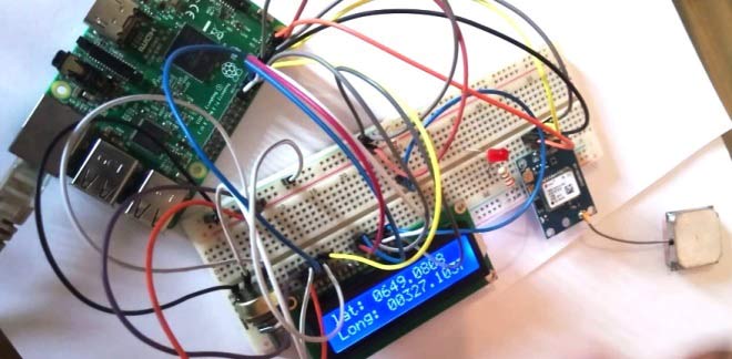
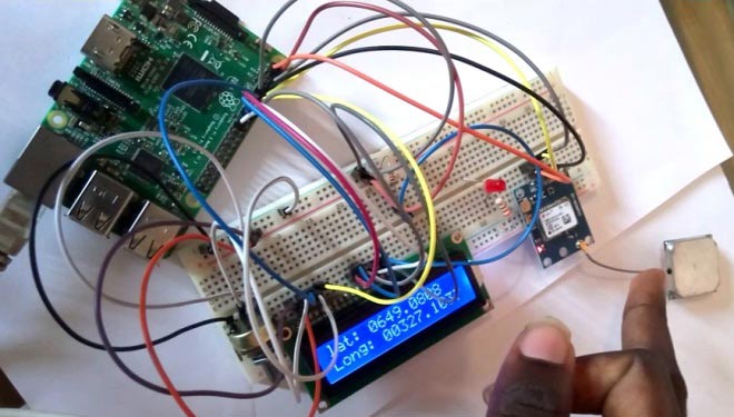
Connections for Raspberry Pi GPS module Interfacing:
Connect the GPS Module and LCD to the Raspberry Pi as shown in the Circuit Diagram below.

Testing before Python Script:
I feel its important to test the GPS module connection before proceeding to the python script, We will employ minicom for this. Run the command:
sudo minicom -D/dev/ttyAMA0 -b9600
where 9600 represents the baud rate at which the GPS module communicates. This may be used for once we are sure of data communication between the GPS and the RPI, its time to write our python script.
The test can also be done using cat
sudo cat /dev/ttyAMA0
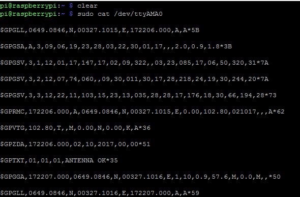
In Window, you can see NMEA sentences which we have discussed earlier.
Python Script for this Raspberry Pi GPS tutorial is given below in Code section.
With all said and done, its time to test the whole system. Its important that you ensure your GPS is getting a good fix, by taking it out, most GPS require between three to 4 satellites to get a fix, although mine worked indoor.
Works Right? Yea…
Have questions or comments? Drop them in the comment section.
Demonstration Video is given below, where we have shown the Location in latitude and longitude on LCD using GPS and Raspberry Pi.
Comments
Not quite sure, a whole lot
Not quite sure, a whole lot of stuff could have been updated in stretch.
How to print the exact coordinates
This tutorial is awesome but i have a little problem solving on how to parse the data in 18.something and 120.something cause when i print in lcd . The value it appears is 1810.something and 12035.something. any suggestion sir?
Code..
Hi! To get less data to handle you could disable some messages from the GPS.
//// Disable unneeded messages from GPS ////
void disableMessages() {
mySerial.println("$PUBX,40,GLL,0,0,0,0*5C");
mySerial.println("$PUBX,40,GSV,0,0,0,0*59");
mySerial.println("$PUBX,40,GSA,0,0,0,0*4E");
mySerial.println("$PUBX,40,VTG,0,0,0,0*5E");
mySerial.println("$PUBX,40,RMC,0,0,0,0*47");
}
Thanks for the tutorial!
Thanks for the tutorial! Everything runs smoothly for me until I try to test with minicom or cat. I'm getting output, but most of it is blank. You don't happen to know what that might be a sign of, do you?
Hi, If you are getting blank,
Hi, If you are getting blank, your GPS is most likely yet to get a fix, I will advise you take it to an open space, although mine worked fine without taking outside..
iam getting this....
iam getting this....
Traceback (most recent call last):
File "/home/pi/Downloads/4.py", line 9, in <module>
ser = serial.Serial(port, baudrate = 9600, timeout = 0.5)
File "/usr/lib/python2.7/dist-packages/serial/serialutil.py", line 261, in __init__
self.open()
File "/usr/lib/python2.7/dist-packages/serial/serialposix.py", line 278, in open
raise SerialException("could not open port %s: %s" % (self._port, msg))
SerialException: could not open port /dev/ttyAMA0: [Errno 13] Permission denied: '/dev/ttyAMA0'
why?
Did you run the script as a
Did you run the script as a superuser?
Sorry about that, blank space
Sorry about that, blank space occurs when your GPS module doesn't have a fix. take it to an open space and try again.
I haven't worked with the
I haven't worked with the SKM53 GPS shield before so can say for sure, but if it communicates with the RPI over serial then the code given above should work
DISPLAY ERROR
Good day.. Please help me. I have tried this but the display looks like this |||| ||||. Can someone help me try to fix this? Please.
Problemas al correr en el IDE PYTHON 3.7
Hola tengo problemas al obtener las coordenadas del GPS en el IDE PYTHON, pero me muestra si introduzco en la linea de comando: sudo python GPS.py
END KERNEL PACNIC
In the step of restarting my raspberry.
when it starts again end appears;
- end kernel panic - not syncing vfs unable to mount root fs on unknown-block(179 2),
what is the problem????

Hi! Will a Raspbian Stretch work out fine for the code above?