

Li-Fi (Light Fidelity) is an advanced technology that allows transferring data using optical communication, such as visible light. Li-Fi data can travel through the light and then be interpreted on the receiver side using any light-sensitive device, like an LDR or a photodiode. Li-Fi communication can be 100 times faster than Wi-Fi. In this comprehensive guide, we'll demonstrate how to build a complete Li-Fi transmitter and receiver using Arduino, enabling text data communication through visible light pulses using a 4x4 keypad as input and a 16x2 LCD display for output.
Here in this project, we will be demonstrating Li-Fi communication using two Arduinos. Here, the text data is transmitted using an LED and a 4x4 keypad. And it is decoded on the receiver side using LDR. We previously explained Li-Fi in detail and used Li-Fi to transfer audio signals. To understand the basics of infrared communication in audio devices, check out this comprehensive IR-based wireless audio transmitter and receiver project, which includes a full schematic and component list.
Table of Contents
- Components Required
- What is Li-Fi Technology?
- Li-Fi vs Wi-Fi
- Building the Li-Fi Transmitter Circuit Using Arduino
- Li-Fi Transmitter Circuit Diagram and Hardware Setup
- Building the Li-Fi Receiver Module with Arduino
- Circuit Diagram and LDR Sensor Integration
- Arduino Code for Li-Fi Transmitter Module
- GitHub Repository
- Troubleshooting
- Testing Your Li-Fi Data Transfer System
Components Required for Li-Fi Transmitter and Receiver System
- Arduino UNO
- LDR Sensor
- 4*4 Keypad
- 16*2 Alphanumeric LCD
- I2C Interface module for LCD
- Breadboard
- Connecting Jumpers
- 5 mm LED
What is Li-Fi Technology and How Does It Work?

As discussed above, Li-Fi is an advanced communication technology which can be 100 times faster than Wi-Fi communication. Using this technology, the data can be transferred using visible light sources. Imagine if you could access high-speed internet just by using your light source. Isn’t it fascinating?
Li-Fi uses visible light as a communication medium for the transmission of data. An LED can act as a light source, and the photodiode acts as a transceiver that receives light signals and transmits them back. By controlling the light pulse at the transmitter side, we can send unique data patterns. This phenomenon occurs at extremely high speed and can't be seen through the human eye. Then, at the receiver side, the photodiode or Light-dependent resistor (LDR) converts the data into useful information. Unlike traditional Wi-Fi systems, a Li-Fi data transfer system can achieve speeds up to 100 times faster while offering enhanced security.
Li-Fi vs Wi-Fi: Quick Comparison
| Feature | Li-Fi Technology | Wi-Fi Technology |
| Data Transmission Medium | Visible light (LED) | Radio waves |
| Speed Potential | Up to 100× faster | Standard wireless speed |
| Security | Higher (light cannot penetrate walls) | Lower (signals pass through walls) |
| Components Required | LED, LDR/Photodiode, Arduino | Router, Network adapter |
| Line of Sight | Required | Not required |
| Interference | Minimal (isolated by walls) | Possible from other devices |
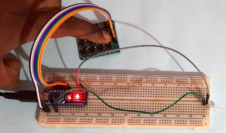
Building the Li-Fi Transmitter Circuit Using Arduino
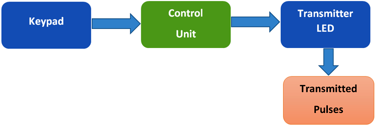
The Li-Fi transmitter circuit forms the core of our data transmission system. As shown in the figure above, in the transmitter part of Li-Fi communication, the keypad is used as input here. That means we’ll be selecting the text to be transmitted using the keypad. Then the information is processed by the control unit, which is nothing but Arduino in our case. Arduino converts the information into binary pulses, which can be fed to an LED source for transmission. Then these data are fed to the LED light, which sends the visible light pulses to the receiver side. In this Li-Fi communication project, the transmitter section uses an LED as the light source. This Li-Fi transmitter module demonstrates the fundamental principles of optical wireless communication.
Li-Fi Transmitter Circuit Diagram and Hardware Setup
Circuit Diagram of Transmitter Section:

Transmitter Pin Connections:
- Keypad Rows (R1-R4): Connect to Arduino pins A5, A4, A3, A2
- Keypad Columns (C1-C4): Connect to Arduino pins A1, A0, 12, 11
- LED Positive (Anode): Connect to Arduino digital pin 8 through a 220Ω resistor
- LED Negative (Cathode): Connect to Arduino GND
- Power Supply: Arduino powered via USB or 7-12V DC adapter
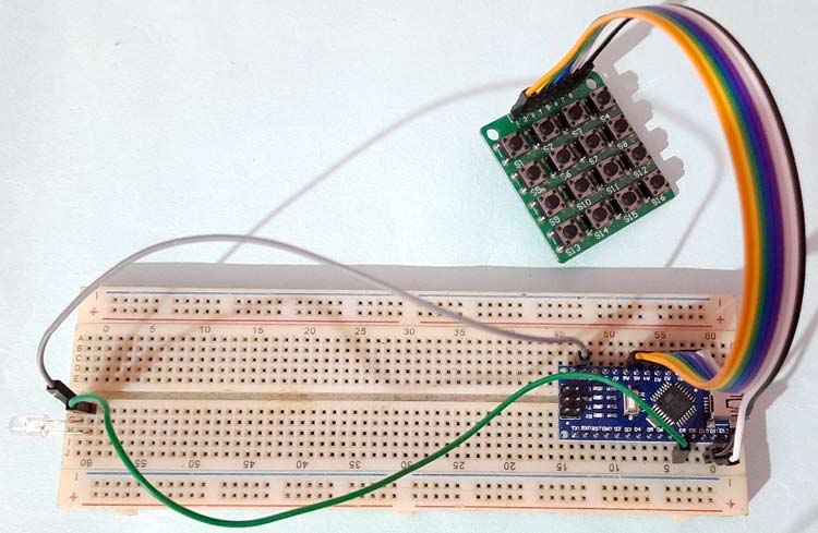
Hardware Setup for Transmitter Side:
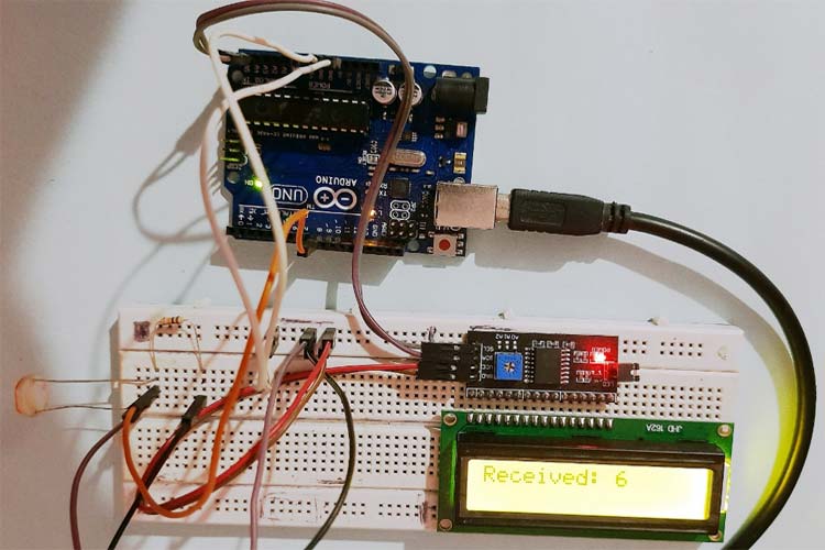
Building the Li-Fi Receiver Module with Arduino

In the receiver section, the LDR sensor receives the visible light pulses from the transmitter side. It converts them into interpretable electrical pulses, which are fed to the Arduino (Control unit). Arduino receives this pulse and converts it into actual data, and displays it on a 16x2 LCD display.
Li-Fi Receiver Circuit Diagram and LDR Sensor Integration
Circuit Diagram of Receiver Section:

Receiver Pin Connections:
- LDR Sensor: One terminal to +5V, other terminal to Arduino pin 8 and 10kΩ resistor
- 10kΩ Resistor: Connect between Arduino pin 8 and GND (forms a voltage divider)
- I2C LCD SDA: Connect to Arduino A4 (SDA pin)
- I2C LCD SCL: Connect to Arduino A5 (SCL pin)
- I2C LCD VCC: Connect to Arduino 5V
- I2C LCD GND: Connect to Arduino GND
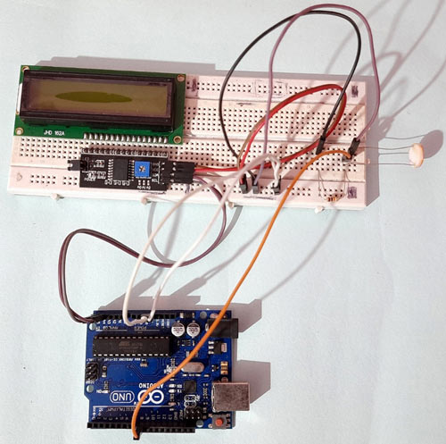
Hardware Setup for Receiver Side:
Arduino Code for Li-Fi Transmitter Module
As shown above, we have two sections for the Li-Fi Transmitter and Receiver. The complete codes for each section are given at the bottom of the tutorial, and a stepwise explanation of the code is given below:
Arduino Li-Fi Transmitter Code:
On the Transmitter side, Arduino Nano is used with a 4x4 Keypad and an LED. First, all the dependent library files are downloaded and installed on Arduino via Arduino IDE. Here, the Keypad library is used for using a 4*4 Keypad, which can be downloaded from this link. Learn more about interfacing a 4x4 keypad with Arduino here.
#include <Keypad.h>After the successful installation of library files, define the no. of rows and column values, which is 4 for both, as we have used a 4*4 keypad here.
const byte ROW = 4;
const byte COL = 4;
char keyscode[ROW][COL] = {
  {'1', '2', '3', 'A'},
  {'4', '5', '6', 'B'},
  {'7', '8', '9', 'C'},
  {'*', '0', '#', 'D'}
};
Then, the Arduino pins are defined that are used to interface with the 4*4 keypad. In our case, we have used A5, A4, A3, and A2 for R1, R2, R3, R4 respectively, and A1, A0, 12, 11 for C1, C2, C3, and C4 respectively.
byte rowPin[ROW] = {A5, A4, A3, A2};
byte colPin[COL] = {A1, A0, 12, 11};
Keypad customKeypad = Keypad( makeKeymap(keyscode), rowPin, colPin, ROW, COL);
Inside setup (), the output pin is defined, where the LED source is connected. Also, it is kept OFF while switching ON the device.
void setup()
{
  pinMode(8,OUTPUT);
  digitalWrite(8,LOW);
}
Inside the while loop, the values received from the keypad are read using customKeypad.getKey(), and it is compared in the if-else loop to generate unique pulses in each key press. It can be seen in the code that the timer intervals are kept unique for all the key values.
char customKey = customKeypad.getKey();
  if (customKey) {
   if (customKey == '1')
  {
    digitalWrite(8,HIGH);
    delay(10);
    digitalWrite(8,LOW);
  }
Arduino Li-Fi Receiver Code:
On the Li-Fi receiver side, Arduino UNO is interfaced with an LDR sensor as shown in the circuit diagram. Here, the LDR sensor is connected in series with a resistor to form a voltage divider circuit and the Analog voltage output from the sensor is fed to the Arduino as an input signal. Here we are using an I2C module with LCD to reduce the number of connections with Arduino, as this module requires only 2 data pins, SCL/SDA and 2 power pins.
Start the code by including all the required library files in the code, like Wire.h for I2C communication, LiquidCrystal_I2C.h for LCD, etc. These libraries would be pre-installed with Arduino, so there is no need to download them.
#include <Wire.h>
#include <LiquidCrystal_I2C.h>
For using the I2C module for a 16*2 Alphanumeric LCD, configure it using the LiquidCrystal_I2C class. Here we have to pass the address, row, and column number, which are 0x3f, 16, and 2, respectively, in our case.
LiquidCrystal_I2C lcd(0x3f, 16, 2);Inside setup (), declare the pulse input pin for receiving the signal. Then print a welcome message on the LCD, which will be displayed during the initialisation of the project.
void setup()
{
  pinMode(8, INPUT);
  Serial.begin(9600);
  lcd.init();
  lcd.backlight();
  lcd.setCursor(0, 0);
  lcd.print("       WELCOME TO              ");
  lcd.setCursor(0, 1);
  lcd.print("     CIRCUIT DIGEST              ");
  delay(2000);
  lcd.clear();
}
Inside the while loop, the pulse input duration from LDR is calculated using the pulseIn function, and the type of pulse is defined, which is LOW in our case. The value is printed on the serial monitor for debugging purposes. It is suggested to check the duration, as it might be different for different setups.
 unsigned long duration = pulseIn(8, HIGH);
 Serial.println(duration);
After checking the durations for all the transmitter pulses, we now have 16 pulse duration ranges, which are noted down for reference. Now compare them using an IF-ELSE loop to get the exact data that has been transmitted. One sample loop for Key 1 is given below:
if (duration > 10000 && duration < 17000)
  {
    lcd.setCursor(0, 0);
    lcd.print("Received: 1          ");
  }
Technical Summary and GitHub Repository
Explore the complete technical breakdown of the project, including circuit design, code, and implementation details. Access the full source code, schematics, and documentation on our official GitHub repository for easy replication and modification.


Troubleshooting Your Li-Fi Data Transfer System
| Problem | Possible Cause | Solution |
| No data received on LCD | Poor LED-LDR alignment or excessive distance | Ensure direct line-of-sight; reduce distance to 10-15cm initially; verify LED is blinking |
| Random characters displayed | Ambient light interference | Test in darker environment; cover LDR with tube/shield to focus on LED only |
| LCD shows wrong characters | Incorrect pulse duration thresholds | Open Serial Monitor, check actual pulse durations, adjust if-else condition ranges |
| Intermittent data reception | Loose connections or poor breadboard contact | Check all jumper wire connections; ensure firm breadboard insertions; verify power supply |
| LED not blinking when keys pressed | Code upload issue or wrong pin connection | Verify LED connected to pin 8 with 220Ω resistor; re-upload transmitter code |
| LCD shows nothing (blank screen) | Wrong I2C address or wiring issue | Try address 0x27 if 0x3F doesn't work; verify I2C module connections (SDA→A4, SCL→A5) |
| Serial Monitor shows zero durations | LDR not receiving light or wrong pin | Verify LDR connected to pin 8; check voltage divider circuit; test LDR with multimeter |
| Inconsistent pulse readings | Unstable power supply or electrical noise | Use regulated 5V power supply; add 100µF capacitor across Arduino power pins |
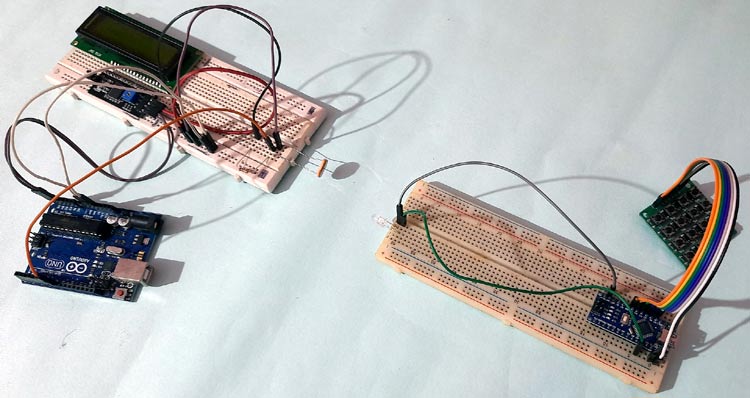
Testing the Li-Fi Data Transfer System
After uploading the complete code in both the Arduinos, press any button on the keypad at the receiver side, and the same digit will be displayed on the 16x2 LCD at the receiver side. This demonstrates successful Li-Fi data transmission using optical wireless communication.
Real-World Applications of Li-Fi Technology
| Application Area | Use Case | Benefits |
| Healthcare/Hospitals | Medical device communication in operating rooms and MRI facilities | No electromagnetic interference with sensitive medical equipment; enhanced patient safety |
| Aviation & Aircraft | In-flight entertainment and high-speed internet using cabin LED lights | No interference with navigation systems; passengers use existing overhead lighting infrastructure |
| Underwater Communication | Submarine and underwater robot data transmission | Light penetrates water better than radio waves; enables deep-sea exploration data links |
| Military & Defense | Secure tactical communications in sensitive areas | Light signals cannot penetrate walls; prevents eavesdropping and signal interception |
| Smart Cities & Streets | LED streetlights providing location-based services and internet access | Dual-purpose infrastructure; energy-efficient public internet connectivity |
| Industrial Automation | Manufacturing plant data networks in RF-sensitive environments | No radio interference; safe in explosive/hazardous environments |
| Retail & Museums | Indoor navigation and product information delivery via ceiling lights | Precise location tracking; enhanced customer experience with contextual information |
| Financial Institutions | Secure banking communications and high-frequency trading floors | Confined signals prevent external hacking; ultra-low latency for trading applications |
The complete Li-Fi data transmission project illustrates the underlying concepts of optical wireless communication using inexpensive Arduino parts. You have practised building both transmitter and receiver circuits, learned about pulse-based encoding/decoding, and also troubleshooting common Li-Fi issues. The entire circuit schematic, Arduino code, and hardware build are all provided to allow you to build again and make modifications as you see fit.
This comprehensive project implementing Li-Fi data transfer demonstrates how light can transmit data instead of radio waves. You have learned to assemble a complete Li-Fi light transmitter and light receiver using Arduino, and demonstrated basic principles of optical wireless communication and problem shooting. The technology that we present here is the future of secure high-speed data transfer, applicable to various industries (e.g., healthcare, aviation, underwater, smart cities).
This is how Li-Fi can be used to transmit data through light. We hope you enjoyed this comprehensive tutorial and, as part of it, learned new and important skills in optical communication, Arduino programming and electronic circuit development. Whether you are a student, hobbyist or professional engineer, this Li-Fi project represents an excellent and substantial first step for you to explore wireless communication technologies in more detail. If you have any doubts, you can use the comment section or ask in the forum.
Frequently Asked Questions About Li-Fi Arduino Projects
⇥ 1. Can I construct a Li-Fi transmitter and receiver module by myself?
Yes, it is a simple build to create a Li-Fi data transmission system using Arduino, an LED, an LDR sensor, and minimal electronics. You will need some intermediate electronics and Arduino programming experience to compile and make this device. On a cost estimate, it would run about $30-40 for the components. The full circuit diagram of the Li-Fi circuit, as well as the code, is given out in this tutorial. It will also be useful to those who are a hobbyists or students.
⇥ 2. How does an LDR sensor work in a Li-Fi receiver system?
An LDR (Light Dependent Resistor) measures the variation of light intensity from the LED in the transmitter. As the intensity of the light changes, the resistance of the LDR changes in reaction. The resistance change will create voltage variations in a voltage divider that is a part of the circuit using a 10kΩ resistor. The Arduino analog pin reads these voltage changes to, count the pulse timing patterns, using the pulseIn() function, and recreate the original data that was sent.
⇥ 3. What standard problems might arise in practical Li-Fi data transmission projects?
Standard problems include: interfering light affecting readings coming from LDR's, poor alignment of the LED and LDR, which may interrupt the signal, using too low of a threshold in the pulse timing on the receiver's code, insufficient LED brightness for distance, and breadboarding that is not properly seated, causing loose connections. The following is suggested: line-of-sight for the transmitter and receiver, reduce any white noise from external sources of light, and look at the timing of the threshold in the pulse duration within the code for optimal performance.
⇥ 4. Can Li-Fi technology function in bright daylight?
Simple Arduino Li-Fi projects fail under bright daylight because ambient light swamps the LDR sensor. Practical workarounds involve the use of infrared LEDs with matching photodiodes (which filter out visible light), optical bandpass filters placed in the path of ambient light to block it, advanced signal processing with noise suppression algorithms, or the Li-Fi system being placed in controlled lighting environments with little sunlight.
⇥ 5. What is the rate of data transmission that Arduino Li-Fi can transmit?
Arduino-based Li-Fi projects can generally transmit data at a rate of around 100-500 bits per second. This is good enough for sending text messages and simply transmitting sensor values. Many factors limit the speed, including the processing ability of the microcontroller (16 MHz), the switching time of the LED's response, and the light-sensing time of the LDR. Industrial-quality Li-Fi systems using specialised hardware, advanced modulation schemes, and high-frequency photodiodes operate in the gigabit range for functions such as live video streaming.
⇥ 6. Is a 4×4 keypad needed for Li-Fi transmitter projects?
Of course, a 4×4 keypad is one input method that is convenient to use but not required for Li-Fi data transmission. The keypad can be substituted with the following: smartphone applications using a Bluetooth module, input via serial monitor through USB connection to computer, sensor readings (temperature, humidity, motion), pre-programmed message sequences from EEPROM, or using push buttons for ease of control. A keypad project provides manual character entry at one time to demonstrate Li-Fi.
⇥ 7. Are there any practical uses of Li-Fi technology in everyday life?
Li-Fi applications are: wireless secure communication within defense setups and banks where radio waves are barred, internet at high speed in aircraft cabins through overhead LED lights, submarine communication systems where radio does not work, hospital data transmission free from electromagnetic interference on medical devices, intelligent lighting systems with embedded data networks, indoor positioning systems for navigation within shopping centers and museums, and vehicle-to-vehicle (V2V) communication through headlights and taillights.
Projects Similar to Li-Fi Technology
Li-Fi has powered many of our most interesting projects. Explore the full range of tutorials and circuit guides through the links provided.

Wireless Audio Transfer Using LASER Light
In this article, we are going to discuss how to transfer audio through laser light. This is a fun little project, and the concept is similar to what we see in fibre optics cable. We will use a laser light to send data from one point to another.

The demand for faster and safer internet has made the highly intuitive human brain develop a new wireless technology called Li-Fi. What is this new term Li-Fi and how does it differ from Wi-Fi?
The term Li-Fi stands for “Light Fidelity”. This is believed to be the next generation of the internet, where Light will be used as a medium to transport data. Yes, you read it right; it is the same Light that you use in your homes and offices, which, with some modification,s can be used to transmit data to all your devices that require internet.
Complete Project Code
//Transmitter Side:
#include <Keypad.h>
const byte ROW = 4;
const byte COL = 4;
char keyscode[ROW][COL] = {
  {'1', '2', '3', 'A'},
  {'4', '5', '6', 'B'},
  {'7', '8', '9', 'C'},
  {'*', '0', '#', 'D'}
};
byte rowPin[ROW] = {A5, A4, A3, A2};
byte colPin[COL] = {A1, A0, 12, 11};
Keypad customKeypad = Keypad( makeKeymap(keyscode), rowPin, colPin, ROW, COL);
char keycount = 0;
char code[5];
void setup()
{
  Serial.begin(9600);
  pinMode(8,OUTPUT);
  digitalWrite(8,LOW);
}
void loop()
{
  char customKey = customKeypad.getKey();
  if (customKey) {
    Serial.println(customKey);
   if (customKey == '1')
  {
    digitalWrite(8,HIGH);
    delay(10);
    digitalWrite(8,LOW);
  }
  else if (customKey == '2')
  {
    digitalWrite(8,HIGH);
    delay(20);
    digitalWrite(8,LOW);
  }
  else if (customKey == '3')
  {
    digitalWrite(8,HIGH);
    delay(30);
    digitalWrite(8,LOW);
  }
  else if (customKey == '4')
  {
    digitalWrite(8,HIGH);
    delay(40);
    digitalWrite(8,LOW);
  }
  else if (customKey == '5')
  {
    digitalWrite(8,HIGH);
    delay(50);
    digitalWrite(8,LOW);
  }
  else if (customKey == '6')
  {
    digitalWrite(8,HIGH);
    delay(60);
    digitalWrite(8,LOW);
  }
  else if (customKey == '7')
  {
    digitalWrite(8,HIGH);
    delay(70);
    digitalWrite(8,LOW);
  }
  else if (customKey == '8')
  {
    digitalWrite(8,HIGH);
    delay(80);
    digitalWrite(8,LOW);
  }
  else if (customKey == '9')
  {
    digitalWrite(8,HIGH);
    delay(90);
    digitalWrite(8,LOW);
  }
  else if (customKey == '*')
  {
    digitalWrite(8,HIGH);
    delay(100);
    digitalWrite(8,LOW);
  }
  else if (customKey == '0')
  {
    digitalWrite(8,HIGH);
    delay(110);
    digitalWrite(8,LOW);
  }
  else if (customKey == '#')
  {
    digitalWrite(8,HIGH);
    delay(120);
    digitalWrite(8,LOW);
  }
  else if (customKey == 'A')
  {
    digitalWrite(8,HIGH);
    delay(130);
    digitalWrite(8,LOW);
  }
  else if (customKey == 'B')
  {
    digitalWrite(8,HIGH);
    delay(140);
    digitalWrite(8,LOW);
  }
  else if (customKey == 'C')
  {
    digitalWrite(8,HIGH);
    delay(150);
    digitalWrite(8,LOW);
  }
  else if (customKey == 'D')
  {
    digitalWrite(8,HIGH);
    delay(160);
    digitalWrite(8,LOW);
  }
  else;
  }
}


//Receiver Side:
#include <Wire.h>
#include <LiquidCrystal_I2C.h>
LiquidCrystal_I2C lcd(0x27, 16, 2);
#include <SoftwareSerial.h>
#include <Keypad.h>
void setup()
{
  pinMode(8, INPUT);
  Serial.begin(9600);
  lcd.init();
  lcd.backlight();
  //lcd.backlight();
  lcd.setCursor(0, 0);
  lcd.print("   WELCOME TO    ");
  lcd.setCursor(0, 1);
  lcd.print(" CIRCUIT DIGEST    ");
  delay(2000);
  lcd.clear();
}
void loop()
{
  unsigned long duration = pulseIn(8, HIGH);
  Serial.println(duration);
  if (duration > 10000 && duration < 17000)
  {
    lcd.setCursor(0, 0);
    lcd.print("Received: 1          ");
  }
  else if (duration > 20000 && duration < 27000)
  {
    lcd.setCursor(0, 0);
    lcd.print("Received: 2          ");
  }
  else if (duration > 30000 && duration < 37000)
  {
    lcd.setCursor(0, 0);
    lcd.print("Received: 3          ");
  }
  else if (duration > 40000 && duration < 47000)
  {
    lcd.setCursor(0, 0);
    lcd.print("Received: 4          ");
  }
  else if (duration > 50000 && duration < 57000)
  {
    lcd.setCursor(0, 0);
    lcd.print("Received: 5          ");
  }
  else if (duration > 60000 && duration < 67000)
  {
    lcd.setCursor(0, 0);
    lcd.print("Received: 6          ");
  }
  else if (duration > 70000 && duration < 77000)
  {
    lcd.setCursor(0, 0);
    lcd.print("Received: 7          ");
  }
  else if (duration > 80000 && duration < 87000)
  {
    lcd.setCursor(0, 0);
    lcd.print("Received: 8          ");
  }
  else if (duration > 90000 && duration < 97000)
  {
    lcd.setCursor(0, 0);
    lcd.print("Received: 9          ");
  }
  else if (duration > 100000 && duration < 107000)
  {
    lcd.setCursor(0, 0);
    lcd.print("Received: *          ");
  }
  else if (duration > 110000 && duration < 117000)
  {
    lcd.setCursor(0, 0);
    lcd.print("Received: 0          ");
  }
  else if (duration > 120000 && duration < 127000)
  {
    lcd.setCursor(0, 0);
    lcd.print("Received: #          ");
  }
  else if (duration > 130000 && duration < 137000)
  {
    lcd.setCursor(0, 0);
    lcd.print("Received: A          ");
  }
  else if (duration > 140000 && duration < 147000)
  {
    lcd.setCursor(0, 0);
    lcd.print("Received: B          ");
  }
  else if (duration > 150000 && duration < 157000)
  {
    lcd.setCursor(0, 0);
    lcd.print("Received: C          ");
  }
  else if (duration > 160000 && duration < 167000)
  {
    lcd.setCursor(0, 0);
    lcd.print("Received: D          ");
  }
}
Comments
void loop()
{
unsigned long duration = pulseIn(8, HIGH);
Serial.println(duration); AM NOT GETING OUTPUT HERE
Hey, thank you for sharing your knowledge. It helped me a lot for my own LiFi project
nothing is happening, not getting any output can anyone explain please??
Not getting output. Only the transmitter part is working. Can any one please help me
Not getting output
Worked correctly .... thanks for your input .. there was few code changes

am not getting an output can someone debug it for me?