

Thermal printer technology has revolutionised receipt printing in retail, healthcare, and IoT projects. This comprehensive ESP32 thermal printer tutorial covers how to interface popular thermal printers, such as the PNP-500, with ESP32 and Arduino microcontrollers. Whether you're building an ESP32 receipt printer, barcode printer, or QR code printing system, this guide provides complete circuit diagrams, Arduino code, and step-by-step instructions for your microcontroller projects.
Thermal printers are widely used in point-of-sale systems, medical equipment, and embedded applications because they require no ink, operate silently, and offer fast printing speeds. By interfacing a thermal printer with ESP32, you can create powerful IoT printing solutions for smart home automation, industrial monitoring, or custom receipt printing systems. Previously, we have also covered how to use a thermal printer with Arduino Uno and how to use a thermal printer with Raspberry Pi. You can check them out if you are interested.
ESP32 Thermal Printer Interface - Quick Overview
Build Time: 3-5 hours | Cost: $30-50 | Difficulty: Beginner-Intermediate
What You'll Learn: UART communication, ESC/POS commands, Bitmap image processing, QR code and barcode printing
Applications: Receipt printing, IoT monitoring, Smart home automation, Barcode labelling
Table of Contents
Understanding Thermal Printer Basics
Thermal printing is a non-impact printing method that uses heat to produce images or text on specially coated heat-sensitive paper, known as thermal paper. It prints by passing the thermal paper over a print head that is specifically designed for this purpose, which has heating elements arranged in a fine line or dot matrix. When specific areas of the thermal paper are heated, a chemical reaction causes those spots to darken, creating the required print.
The thermal paper for this printer starts from 57mm, 76mm, 80mm, up to 110mm in width, and ranges from 15m to 70m in length. So, depending on the machine’s capability, specific widths and lengths of paper are used.
Thermal Printer Types Comparison
Direct thermal printing is most commonly used where the printed information does not need to last long, such as retail POS receipts, event tickets, and short-term barcode labels.
On the other hand, thermal transfer printing is preferred for applications that require more durable and long-lasting prints. This includes labelling for chemicals and outdoor products, as well as patient identification in healthcare settings.
Advantages
- No ink or toner required (for direct thermal printers).
- Low maintenance due to fewer moving parts.
- Silent and fast operation.
- Simple electronic interface suitable for microcontroller integration.
Disadvantages
- Prints can fade with heat, light, or friction (primarily direct thermal).
- Limited to monochrome in most models.
- Special thermal paper is required.
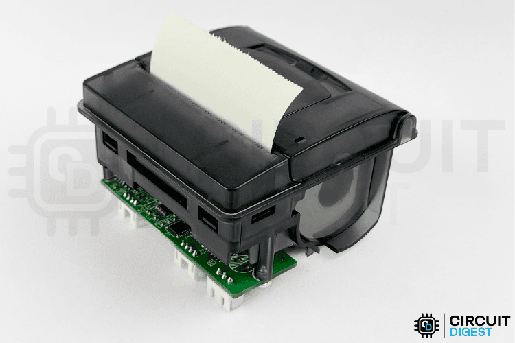
PNP-500 Thermal Printer: For ESP32 and Arduino Projects
The PNP-500 is a compact, panel-mount thermal printer that's simple to use and highly reliable, making it a favourite for industrial and measurement applications. You'll often find it integrated into diagnostic equipment, control panels, and weighing scales, where space is tight and speed matters.
There is another printer available, the RS203, which is quite similar to the PNP-500. So, this ESP32 with thermal printer tutorial also works with the RS203 model.
Key Technical Specifications
⇒ Printing Method: Direct thermal line printing. This means it prints by selectively heating thermal paper.
⇒ Paper Width: 57mm, perfect for standard receipts and data logs.
⇒ Print Width: 48mm.
⇒ Print Speed: 50–80mm/sec, offering fast output for most needs.
⇒ Resolution: 8 dots/mm (384 dots/line), ensuring crisp text and barcodes.
⇒ Interfaces: Serial (RS232C, TTL) and USB, so you have options for how to connect.
⇒ Operating Voltage: 5–9V DC, and can handle up to 12V.
⇒ Dimensions: 76.8×77.4×47.6mm (WxDxH)—small enough to fit in tight control panels.
⇒ Max Paper Roll: 58mm wide, 40mm diameter, which covers most long-printing needs.
⇒ Print Head Life: Up to 50km of printing, so it's built to last.
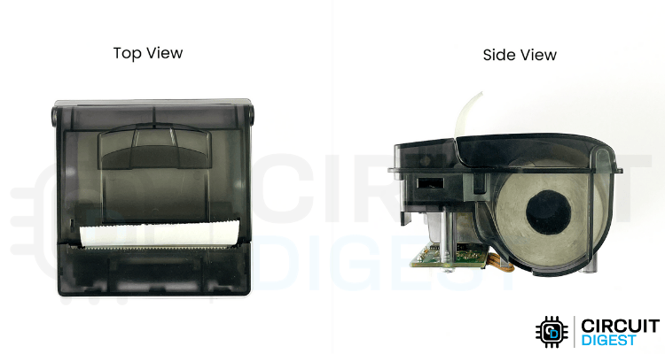
Dimensions of PNP500 Thermal Printer
The physical dimensions of this printer can be found in the image below.
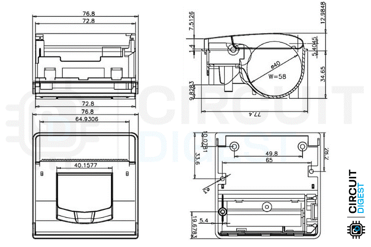
With all these outlined dimensions, it's easy for you to plan the cutout for the enclosure in your project or 3d printable case, etc.
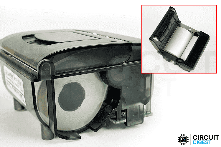
Hardware Overview of the PNP-500 Thermal Printer
Now let’s do a deep dive into the hardware parts and their working. To make this clear, I have disassembled the printer completely so that everything is easy to understand.
Below, you can see the fully disassembled PNP500
Be careful if you also plan to disassemble it for learning purposes. Make sure the plastic hinges are opened correctly, or they might break easily. This requires solid patience.
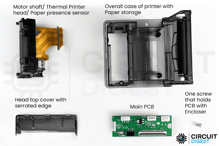
Now, let’s discuss more about the parts of the printer.
This PNP-500 thermal printer has a total of 6 most important parts to understand. They are,
1. Main control PCB
There is only one PCB in this printer that handles all the functions. So, let’s understand the PCB, starting from the top view.
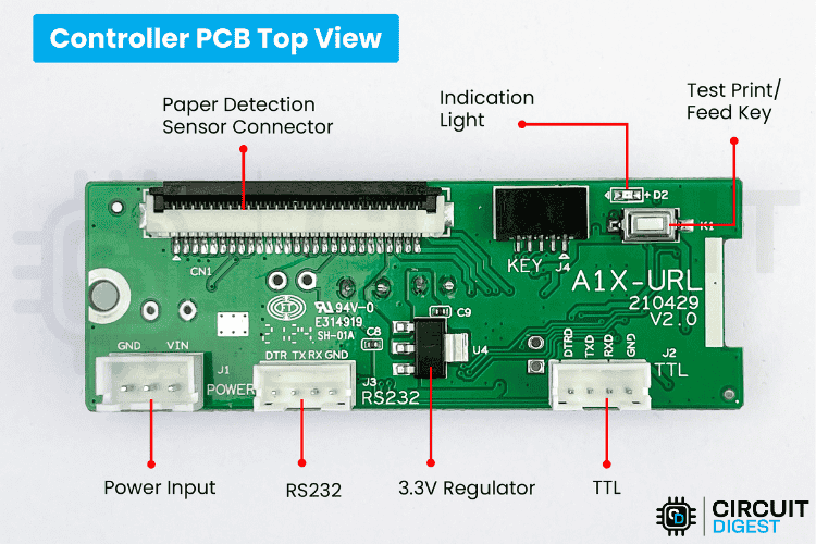
In the image above with marked parts, you can identify the purpose of each I/O pin for interfacing a thermal printer with the ESP32 pinout. For communication, this module provides two options: RS232 and TTL. If you are using a microcontroller, the TTL port is very easy to integrate.
You can also find the power input pin. This supports a wide voltage range of 5V–9V, or 12V DC, as stated in the paper. However, I didn’t get perfect printing results with 5V. A voltage above 6V gave me the right darkness. Specifically, I used a 2S Li-ion battery pack to power the module.
Understanding how to use interfacing thermal printer with the ESP32 pinout makes it easier to get a perfect connection, and you can follow the complete wiring setup in the thermal printer ESP32 wiring diagram.
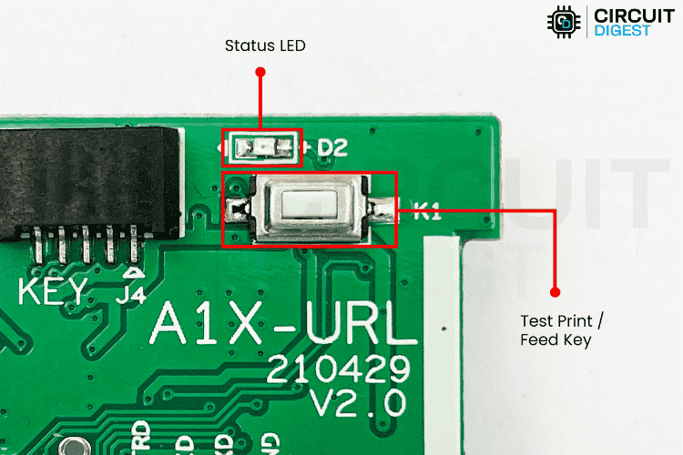
Next, there is an LED marked as D2, which is a status LED. Its status indicators are as follows:
Blinks once: Working properly
Blinks twice: No printer detected
Blinks three times: No paper detected
Blinks five times: Printer mechanism is overheating
Blinks ten times: No Chinese character stock IC detected
Next, there is a button marked as K1. It has two functionalities:
After pressing it while powering on the device, a test print page is printed, which looks like the following
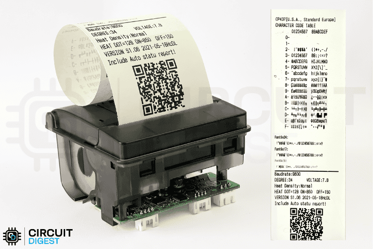
In the test page,
First, the character code table is printed.
Then, demo text for three font sizes is printed (9x24, 9x17, 8x16).
Followed by information such as Baud rate, Degree (head temperature), Voltage, Heat Density (darkness of print), Heat Dot (number of heating elements activated simultaneously), ON/OFF timing, Firmware version, and finally, a QR code indicating "QRCode Support!".
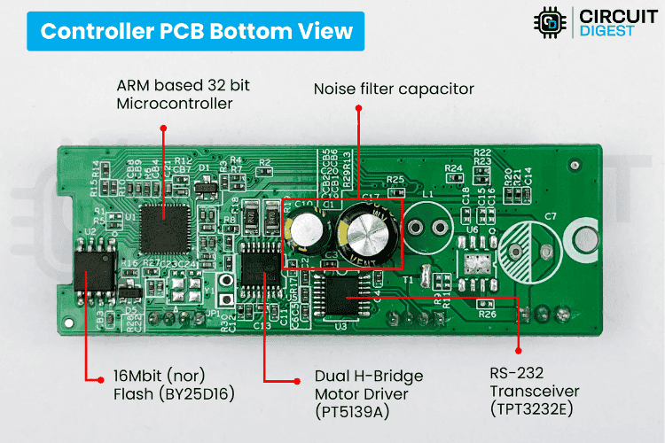
In the image above, you can see the bottom view of the PCB. There are no I/O ports here—just the main ICs:
BY25D16 – A 16MB NOR-type Flash Memory, probably used to store important configuration data and large functions.
PT5139A – A dual H-Bridge motor driver IC used to drive the stepper motor for the paper feed mechanism.
TPT3232E – An RS232 transceiver IC used for RS232 communication.
ARM-based 32-bit MCU – The exact model or part number is unknown, but it serves as the main processor of the printer, running on a 3.3V supply.
2. Print Head
The print head is special, as it’s the main component responsible for the printing process. It’s a tiny mechanism. Practically, there are 384 individual heating elements, which produce 384 individual dots. You can see them in the image below. We verified the count ourselves to confirm it.
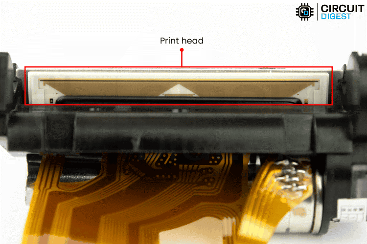
The print head already includes the required shift registers, embedded in the black region below the heating area, which is an IC. This helps reduce the number of control pins to just 6, along with additional GND and power pins.
This thermal print head also includes a thermistor for heat measurement. Along with this, there is a paper detection sensor and a servo motor that connect to the main PCB via the same ribbon cable.
Be careful with the ribbon cable; even though it’s flexible, it can tear easily.
3. Spring Suspension Behind the Print Head
In the image below, you can see the two springs connected to the thermal print head.
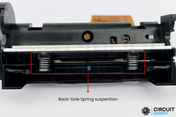
More than just connecting, the springs are used to push the print head against the feeding paper, regardless of its thickness or texture. The goal is to ensure all heating elements make proper contact with the paper for consistent printing.
4. Paper Feeding Mechanism
The paper feeding mechanism consists of five gears, two shafts (connected to the motor and the rubberised roller), a stepper motor, and a rubberised roller.
Below, you can see a close-up of the stepper motor and gear assembly, where a small metal gear is directly connected to the stepper motor. The remaining three gears connect the motor shaft to the main roller shaft.

The gear ratios are pre-calculated and stored in the system. Their purpose is to precisely feed the paper line-by-line, dot-by-dot, according to timing, which ensures perfect printing output.
In the image below, you can see the last gear connected to the roller shaft.
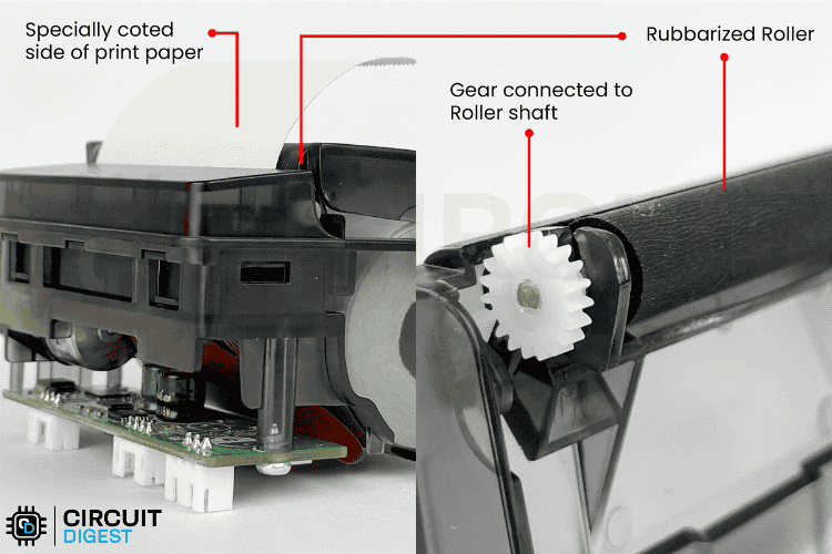
Notice that the roller is attached to the open/close cover of the paper roll storage. When closed, it provides the necessary friction to feed the paper from the back, where the texture is a bit rough, which helps feed the paper smoothly without damage.
Moreover, the coated side of the paper is smoother, allowing it to slide easily toward the print head.
5. IR-Based Paper Presence Detection System
This paper presents detection system is straightforward. It uses an IR-based proximity sensor to detect paper.
The concept is simple. IR light gets reflected only from white, glossy surfaces. If the surface is darker or rough, the photodiode doesn’t receive the reflected light, indicating no paper.
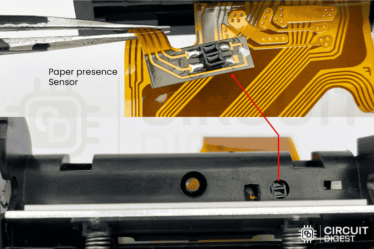
Above, you can see the location and physical appearance of the sensor in the thermal printer.
The paper storage can support up to a maximum of 40mm diameter rolls, which equals approximately 16 to 20 meters in paper length.
Below, you can see a clear picture representing the paper roll storage area.
How to Program a Thermal Printer?
To be more specific, operating such modules is simpler than you think. There’s already a whole lot of command instructions built into the module. Based on the model of the printer you have, you can find the list of commands in the manual or datasheet of the module. These commands are sent to the printer using any of the communication ports available on the module.
In our case, the PNP-500 has TTL (UART) and RS232 ports. Some modules may also have a USB. That’s all!
Now, let me show you the list of commands available for the PNP-500 module.
Thermal Printer Commands
Thermal Printer - Print Quality Control Commands
Below, you can refer to the Density Calculation Formula,
densityLevel = (densityPercent - 50) / 5  // Range: 0-31
breakTimeLevel = breakDelayUs / 250       // Range: 0-7
n = (breakTimeLevel << 5) | (densityLevel & 0x1F)
Commands to Print Bitmap Image
Below, you can see the Bitmap Size Calculation that is used in the code.
bytesPerLine = (width + 7) / 8
xL = bytesPerLine & 0xFF
xH = (bytesPerLine >> 8) & 0xFF
yL = height & 0xFF
yH = (height >> 8) & 0xFF
Now, below you can see the complete sequence used for the Bitmap Image Printing.
1. 0x1B 0x33 0x00 // Line spacing: 0
2. // For each 24-line chunk:
3. 0x1D 0x76 0x30 0x00 xL xH yL yH [chunk] // Print chunk
4. 0x1B 0x64 0x03 // Feed 3 lines at end
Thermal Printer Barcode Configuration Commands
First, you need to do a little configuration before printing the barcode.
After finishing up with the configuration, we can print the barcode,
Below you can see the example commands for barcode printing.
1. CODE128: 0x1D 0x6B 0x49 0x06 "123456"
2. UPC-A: 0x1D 0x6B 0x41 0x0B "12345678901"
3. EAN13: 0x1D 0x6B 0x43 0x0C "123456789012"
Now, below you can see the complete sequence used for the barcode.
0x1D 0x68 0x50 // Height: 80 dots
0x1D 0x77 0x02 // Width: 2x
0x1D 0x48 0x02 // HRI below
0x1D 0x6B 0x49 n [data] // Print barcode (n=data length)
For advanced projects requiring barcode scanning capabilities, you can also consider interfacing a USB barcode scanner with Raspberry Pi 4 to read 2D barcodes, which works seamlessly with thermal printer systems.
QR Code Commands for Thermal Printer
Below you can see the QR Code Data Length Calculation,
len = data.length() + 3
pL = len & 0xFF
pH = (len >> 8) & 0xFF
Also, remember, QR codes come with four error correction levels that determine how much of the code can be restored if it becomes dirty or damaged. Level L (hex value 0x30) offers about 7% recovery and is suitable for clean environments. Level M (0x31) provides around 15% recovery and is the default choice for general use. Level Q (0x32) allows for 25% recovery, making it ideal for cases where moderate damage might occur. Finally, Level H (0x33) offers the highest protection with 30% recovery, recommended for scenarios where the QR code is at high risk of damage.
Now, below you can see the complete sequence used for the QR Code.
1. 0x1D 0x28 0x6B 0x04 0x00 0x31 0x41 0x32 0x00 // Set model 2
2. 0x1D 0x28 0x6B 0x03 0x00 0x31 0x43 0x06 // Module size 6
3. 0x1D 0x28 0x6B 0x03 0x00 0x31 0x45 0x31 // Error level M
4. 0x1D 0x28 0x6B pL pH 0x31 0x50 0x30 [data] // Store data
5. 0x1D 0x28 0x6B 0x03 0x00 0x31 0x51 0x30 // Print QR
More than the number of functions listed above, you can still find additional commands in the official datasheet. In the above section, I have covered only the essential commands.
Now, let’s move on to practical testing.
Hardware Required
For this ESP32 receipt printer project, you'll need the following components: we will be using the ESP32 as the main microcontroller, which is the only hardware required. Still, to make the demonstration easier, I added two button inputs, which will help us trigger certain print commands.
- ESP32 Development Board (Any Model/Brand) – 1
- Thermal Printer (PNP-500 / RS203) – 1
- Resistors (1KΩ) – 2
- Connecting Wires – As Required
- Breadboard – 1
- 2S Li-Ion Battery – 1 (For powering the printer)
- Push Buttons – 2 (Optional)
These components should be enough for the demonstration. As I usually say, you're not limited to just these; feel free to expand or modify based on your needs.
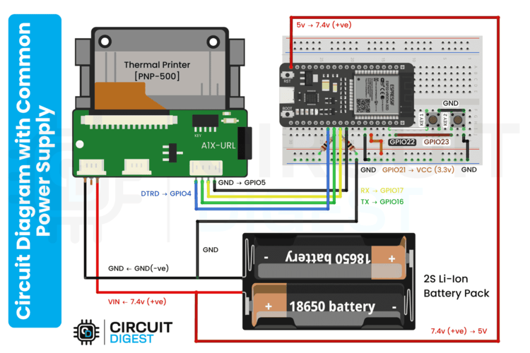
Thermal Printer ESP32 Circuit Diagram
For interfacing the PNP-500 thermal printer with the ESP32 Dev Module, we’ll be using the TTL communication port of the printer. This allows us to use the UART interface of the ESP32. I suggest using the hardware UART for the best performance.

In the ESP32 thermal printer circuit diagram above, you can see the connections between components. I’ve used two pull-up resistors on the RX and TX data lines. Their main purpose is to reduce EM interference or signal noise, especially if you're using long wires.
I’ve also added two push buttons, which, when pressed, will start printing. However, you can also send commands via the Serial Monitor to the ESP32 to trigger printing.
As of now, I’m using two separate power supplies: a 2S Li-ion battery pack for the printer, and USB power for the ESP32. But you can also power both using just the Li-ion battery pack by making a simple modification, connecting the battery’s positive terminal to the 5V (or Vin) pin of the ESP32, and the negative terminal to GND.
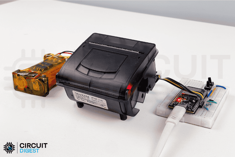
This setup is clearly shown in the image below.
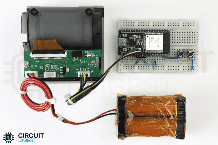
After assembling everything properly, our ESP32 thermal printer circuit is ready for programming. Below, you can see the fully assembled image of our ESP32 with thermal printer.
Project Summary and GitHub Link of ESP32 Thermal Printer
The code for this interface is fairly straightforward, as I’ve included all the necessary functions in the test code. You can find the full code used in this ESP32 with Thermal Printer demo on our GitHub repository linked below.


Note: In addition to the code, you’ll need bitmap data if you want to print an image on a thermal printer. This web app is particularly useful for converting graphics. We have already used this in our Arduino OLED Eyes Animation project, and also Space Race Game using Arduino.
How to Get the Bitmap Binary Code for Printing an Image?
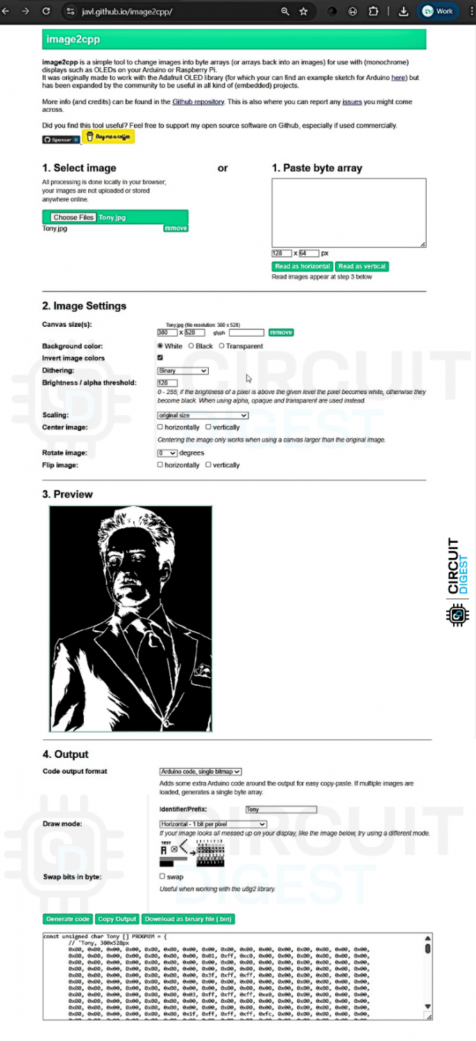
⇒ Step 1:
Open https://javl.github.io/image2cpp/ in any browser.
This web app will help us convert the image into a byte array.
⇒ Step 2:
Upload your image. Make sure its width does not exceed 384px.
⇒ Step 3:
Remember, in thermal printing, the white areas are what get printed. So, invert the image if required.
Also, set the code output format to “Arduino Code; Single bitmap.”
⇒ Step 4:
Click the "Generate Code" button. The byte array will appear in the text box below.
Copy this code and paste it into a file named data.h in your directory.
With that done, we can now move on to reviewing the main code!
ESP32 Code for Thermal Printer Interface
As mentioned earlier, the complete code for this tutorial is on our GitHub repo and also at the bottom of this article. This section explains the important snippets of our ESP32 thermal printer code so that you can modify and adapt it for your use case.
1. Libraries and Headers
#include <Arduino.h>
#include "data.h"
#include <esp_heap_caps.h>
Arduino.h: Core Arduino library providing basic functions like pinMode(), digitalWrite(), Serial, etc.
data.h: Custom header file containing bitmap image data stored in PROGMEM (flash memory). This is mainly for keeping the code organised. Even if you paste the byte array directly into the main code, it will still work.
esp_heap_caps.h: ESP32-specific library for advanced memory management and heap monitoring functions
2. Data Structures and Constants
BitmapImage Structure
struct BitmapImage {
 const char* name;           // Human-readable name for the image
 const unsigned char* data;  // Pointer to image data in PROGMEM
 int width;                  // Image width in pixels
 int height;                 // Image height in pixels
};
This structure organises image metadata, making it easy to manage multiple bitmap images with their names and dimensions.
Available Images Array
const BitmapImage availableImages[] = {
 { "circuitDigestLogo", circuitDigestLogo, 360, 360 },
 { "tony", tony, 380, 528 },
 // ... more images
};
This array creates a catalogue of all available images, stored in flash memory to save RAM. Each entry contains the image name, data pointer, and dimensions.
Hardware Pin Definitions
#define RXD2 16
#define TXD2 17
#define GND 5
#define Vcc 21
#define Key1 22
#define Key2 23
These define the ESP32 GPIO pins used for:
- UART2 (pins 16,17): Serial communication with the thermal printer
- Power control (pins 5,21): Managing the power supply line of the data line and the push button.
- Buttons (pins 22,23): Physical user interface for demo functions
Global Variables
bool globalUpsideDown = true;
unsigned long lastKey1Press = 0;
unsigned long lastKey2Press = 0;
int imageIndex = 0;
const unsigned long debounceDelay = 200;
These variables maintain the system state and handle user input timing.
3. Setup Function - System Initialisation
void setup() {
// Configure power control pins for printer
pinMode(GND, OUTPUT);
pinMode(Vcc, OUTPUT);
digitalWrite(GND, LOW); // Ensure ground is always low
 digitalWrite(Vcc, HIGH);  // Ensure power is always high
 // Configure button input pins with internal pullup resistors
 pinMode(Key1, INPUT_PULLUP);
 pinMode(Key2, INPUT_PULLUP);
 // Initialize serial communications
 Serial.begin(115200);                               // Debug monitor at high speed
 printerSerial.begin(9600, SERIAL_8N1, RXD2, TXD2); // Printer at standard thermal printer baud rate
 delay(1000);  // Give printer time to initialize
 // Set initial printer alignment to center
 align(1);
 // Print memory status and set initial upside-down state
 printMemoryStats("setup done");
 setGlobalUpsideDown(true);  // Default: enable upside-down printing
}
Let's know what happens during setup.
- Power Management: Sets up dedicated pins to control the power supply for the signal line of the printer and push buttons.
- Button Configuration: Enables internal pullup resistors for button inputs (buttons read LOW when pressed)
- Serial Communication:
- USB Serial at 115200 baud for debugging/commands
- Printer Serial at 9600 baud (standard for thermal printers)
- Printer Initialisation: Waits 1 second for printer boot, sets centre alignment
- System State: Checks memory usage and enables upside-down printing by default (Just optional).
4. Loop Function - Main Program Cycle
void loop() {
 // Handle serial command input with static buffer for efficiency
 static String inputBuffer = "";
 inputBuffer.reserve(64);  // Pre-allocate string memory to reduce fragmentation

 // Process incoming serial data character by character
 while (Serial.available()) {
   char c = Serial.read();
   if (c == '\n' || c == '\r') {
     // End of command - process if buffer has content
     if (inputBuffer.length() > 0) {
       handleSerialCommand(inputBuffer);
       inputBuffer = "";  // Clear buffer for next command
     }
   } else {
     inputBuffer += c;
   }
 }
 // Button handling with debouncing
 // Key1: Print next image in sequence
 if (digitalRead(Key1) == LOW) {
   if (millis() - lastKey1Press > debounceDelay) {
     demoPrintNextImage();
     lastKey1Press = millis();
   }
 }
 // Key2: Print comprehensive demo page
 if (digitalRead(Key2) == LOW) {
   if (millis() - lastKey2Press > debounceDelay) {
     demoPrintAllFormats();
     lastKey2Press = millis();
   }
 }
}
Loop function responsibilities are,
- Serial Command Processing: Builds commands character by character, executes when complete
- Button Debouncing: Prevents multiple triggers from mechanical button bounce
- Demo Functions: Key1 cycles through images, Key2 prints comprehensive demo
5. Custom Functions
- handleSerialCommand() - Processes text commands from computer (like "QRCODE Hello")
- setDarknessAndDelay() - Adjusts how dark the print is and printing speed
- printQRCode() - Creates QR codes for websites, text, and contacts
- printBarcode_CODE128/UPCA/EAN13() - Prints barcodes for products and inventory
- printBitmapGS_Method() - Prints images and logos stored in memory
- feedLines() - Moves paper forward by specified lines
- align() - Sets text alignment (left, centre, right)
- upsideDownPrinting() - Flips all printing upside down
- underlineMode() - Adds underlines to text
- inverseMode() - Prints white text on a black background
- printMemoryStats() - Shows how much memory is being used
- rotateBitmap1bpp_180() - Rotates images 180 degrees for upside-down mode
- createTestPattern() - Makes test patterns to check printer quality
- demoPrintNextImage() - Button 1 function - prints next image in list
- demoPrintAllFormats() - Button 2 function - prints an example of everything the printer can do.
You can find the full code in the GitHub link in the above section.
Demonstration of ESP32 with Thermal Printer Project
The working demonstration is quite simple, as I’ve already created all the necessary functions. For this demo, I’m using a separate power supply for the thermal printer. The ESP32 is powered and communicates via serial USB-C cable from my laptop.
Once you’ve successfully uploaded the code, it’s time to test the device. Below, you can see the ESP32 thermal printer printing an image.
The print quality is pretty good, but we did face several issues while getting the image to print correctly. Most common problems can be solved by cleaning the print head using a soft cloth and isopropyl alcohol. Remaining issues were resolved through multiple code revisions, so you don't have to worry about that. Also, make sure the printer has a proper power supply. Supplying only 5V results in poor-quality image prints. However, for text printing, 5V should be sufficient.
Here’s another GIF showing a demonstration of text printing, which also includes the Bar Code and QR Code.
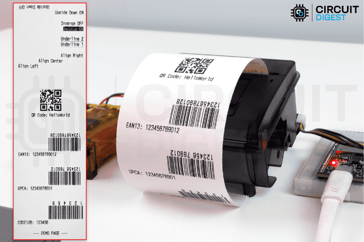
As a bonus, I’ve also provided a code snippet that can print a professional GST invoice using this small ESP32 thermal printer. Feel free to test that out as well! Below you can see the GIF Video of the ESP32 receipt printing.
Frequently Asked Questions on ESP32 with Thermal Printer
⇥ What voltage does the ESP32 thermal printer need?
ESP32 can work with either 3.3V or 5V, but thermal printers like the PNP-500 need a voltage supply of 5-12V. It is recommended for direct printing, and appropriate print darkness and quality are to provide separate power supplies or a 2s Li-ion battery (7.4V) for the printer.
⇥ How to print QR codes with an ESP32 thermal printer?
You need to use the ESC/POS QR commands sequence. It includes first setting the model (GS(k) command 29), applying the module size and error correction level, storing the data using length parameters, and then issuing the print commands. It is also recommended to generate the QR codes dynamically.
⇥ What paper size can I use with the ESP32 thermal printer project?
The PNP-500 can use 57mm width( 2 inch) thermal paper for the print area of 48mm; paper rolls that are less than 40mm in diameter will fit inside the storage compartment, which is about 16-20 meters of printable length of paper.
⇥ What barcode formats can I use with an ESP32 thermal printer project?
ESP32 thermal printers will print CODE128, UPC-A, EAN13 and other formats as we expect in existing barcode formats traditionally used by commercial businesses around the world. Use ESC/POS commands to configure the size of your bar codes, their height, width and HRI text position before sending the respective data commands via UART with the old standard ESC/POS commands.
⇥ How do I troubleshoot issues with my ESP32 with thermal printer project?
The voltage supplied to the printer system, double-check that it is 6V + volts, is provided as is, typically the minimal recommended voltage supply. Clean the print head of your thermal printer with Isopropyl Alcohol (IPA). Inspect toilet connections - verify UART and baud rate (9600). Check that you are using high-quality thermal paper - load properly and inspect that there is no discolouration, and check the state of the ribbon cable connected from the printer's head to the UART chip (if applicable).
With that, we wrap up this tutorial. You’ve learned how thermal printers work, how to interface them, and even how to print custom images and invoices. Whether building an ESP32 receipt printer or integrating barcode functionality, this tutorial provides the foundation for scalable printing solutions. Our project demonstrates how to use an interfacing thermal printer with the ESP32 for various applications. If you have any doubts or face issues, feel free to ask in the comment section below or start a discussion on any of our community platforms.
Projects on Thermal Printer Interfacing
Previously, we have built many thermal printer interfacing projects. If you want to know more about those topics, links are given below.

Thermal Printer Interfacing with Arduino Uno
In this tutorial, learn how to interface a thermal printer with Arduino Uno, using a tactile switch for a push-to-print feature. This step-by-step tutorial covers wiring and setup.

Thermal Printer interfacing with PIC16F877A
Learn how to interface a CSN A1 thermal printer with the popular PIC16F877A microcontroller. This project connects the printer to the PIC microcontroller and uses a tactile switch to trigger printing.

Smart Shopping Cart with POS Thermal Printer, Barcode Scanner, 20x4 LCD and Raspberry Pi
Build a Smart Shopping Cart using Raspberry Pi 3 by interfacing a thermal receipt printer, LCD, and USB barcode scanner. Retrieve item details like name and price from a Google Spreadsheet for efficient and automated shopping.
Complete Project Code
/*
* Thermal Printer Controller for ESP32
*
* Author: Rithik Krisna M / CircuitDigest.com
* Date: August/2025
*
* Serial Commands:
* Type 'HELP' for full list of available commands
*/
#include <Arduino.h>
#include "data.h"
#include <esp_heap_caps.h>
// Struct for bitmap images - contains metadata for each available image
struct BitmapImage {
 const char* name;           // Human-readable name for the image
 const unsigned char* data;  // Pointer to image data in PROGMEM
 int width;                  // Image width in pixels
 int height;                 // Image height in pixels
};
// List of all available images - stored in PROGMEM to save RAM
const BitmapImage availableImages[] = {
 { "circuitDigestLarge", circuitDigestLarge, 360, 360 },
 { "tony", tony, 380, 528 },
 { "naruto", naruto, 380, 615 },
 { "circuitDigestSmall", circuitDigestSmall, 200, 56 },
 { "luffy", luffy, 340, 263 },
 { "luffy2", luffy2, 340, 287 },
 { "SpritedAway", SpritedAway, 380, 395 },
 { "Totoro", Totoro, 360, 500 },
 { "minato", minato, 380, 458 },
 { "itachi", itachi, 380, 733 },
 { "starkIndustriesLogo", starkIndustriesLogo, 380, 61 },
 { "AvengersLogo", AvengersLogo, 380, 456 },
 { "gojo", gojo, 380, 609 }
};
// Calculate number of available images at compile time
const int numAvailableImages = sizeof(availableImages) / sizeof(availableImages[0]);
// Hardware pin definitions for ESP32
#define RXD2 16  // UART2 RX pin for printer communication
#define TXD2 17  // UART2 TX pin for printer communication
// Control pins for printer power management
#define GND 5    // Always LOW - printer ground control
#define DTRD 4   // Not used in current implementation
#define Vcc 21   // Always HIGH - printer power control
// Button input pins with internal pullup
#define Key1 22  // Button 1 - cycles through images
#define Key2 23  // Button 2 - prints demo page
// Serial communication setup
HardwareSerial printerSerial(2);  // Use UART2 for printer communication
// Constants for memory and performance optimization
const int IMAGE_WIDTH = 200;   // Default image width (not currently used)
const int IMAGE_HEIGHT = 56;   // Default image height (not currently used)
const unsigned long debounceDelay = 200;  // Button debounce delay in milliseconds
// Global state variables
bool globalUpsideDown = true;          // Global upside-down printing flag
unsigned long lastKey1Press = 0;      // Last time Key1 was pressed (for debouncing)
unsigned long lastKey2Press = 0;      // Last time Key2 was pressed (for debouncing)
int imageIndex = 0;                   // Current image index for button cycling
// Function prototypes - forward declarations for better organization
void printBitmapGS_Method(const unsigned char* progmemData, int width, int height);
void printTestPattern(int width, int height, int pattern);
void handleSerialCommand(String cmd);
void printMemoryStats(const char* tag);
void setGlobalUpsideDown(bool enable);
// Memory diagnostics helper - prints current heap status for ESP32
void printMemoryStats(const char* tag) {
 Serial.print("[MEM] ");
 Serial.print(tag);
 Serial.print(" | FreeHeap: ");
 Serial.print(ESP.getFreeHeap());
 Serial.print(" | MinFreeHeap: ");
 Serial.print(ESP.getMinFreeHeap());
 Serial.print(" | MaxAllocHeap: ");
 Serial.print(ESP.getMaxAllocHeap());
 Serial.print(" | HeapSize: ");
 Serial.println(ESP.getHeapSize());
}
// Set global upside-down printing mode for all output
void setGlobalUpsideDown(bool enable) {
 globalUpsideDown = enable;
 upsideDownPrinting(enable ? 1 : 0);  // Apply to printer immediately
 Serial.print("Global upside-down set to: ");
 Serial.println(enable ? "ON" : "OFF");
}
// Arduino setup function - runs once at startup
void setup() {
 // Configure power control pins for printer
 pinMode(GND, OUTPUT);
 pinMode(Vcc, OUTPUT);
 digitalWrite(GND, LOW);   // Ensure ground is always low
 digitalWrite(Vcc, HIGH);  // Ensure power is always high
 // Configure button input pins with internal pullup resistors
 pinMode(Key1, INPUT_PULLUP);
 pinMode(Key2, INPUT_PULLUP);
 // Initialize serial communications
 Serial.begin(115200);                               // Debug monitor at high speed
 printerSerial.begin(9600, SERIAL_8N1, RXD2, TXD2); // Printer at standard thermal printer baud rate
 delay(1000);  // Give printer time to initialize
 // Set initial printer alignment to center
 align(1);
 // Print memory status and set initial upside-down state
 printMemoryStats("setup done");
 setGlobalUpsideDown(true);  // Default: enable upside-down printing
}
// Main Arduino loop - handles serial commands and button presses
void loop() {
 // Handle serial command input with static buffer for efficiency
 static String inputBuffer = "";
 inputBuffer.reserve(64);  // Pre-allocate string memory to reduce fragmentation

 // Process incoming serial data character by character
 while (Serial.available()) {
   char c = Serial.read();
   if (c == '\n' || c == '\r') {
     // End of command - process if buffer has content
     if (inputBuffer.length() > 0) {
       handleSerialCommand(inputBuffer);
       inputBuffer = "";  // Clear buffer for next command
     }
   } else {
     inputBuffer += c;
   }
 }
 // Button handling with debouncing
 // Key1: Print next image in sequence
 if (digitalRead(Key1) == LOW) {
   if (millis() - lastKey1Press > debounceDelay) {
     demoPrintNextImage();
     lastKey1Press = millis();
   }
 }

 // Key2: Print comprehensive demo page
 if (digitalRead(Key2) == LOW) {
   if (millis() - lastKey2Press > debounceDelay) {
     demoPrintAllFormats();
     lastKey2Press = millis();
   }
 }
}
// Parse and execute serial commands
void handleSerialCommand(String cmd) {
 cmd.trim();  // Remove leading/trailing whitespace
 if (cmd.length() == 0) return;
 // Split command and parameters for processing
 int spaceIdx = cmd.indexOf(' ');
 String command = (spaceIdx == -1) ? cmd : cmd.substring(0, spaceIdx);
 String params = (spaceIdx == -1) ? "" : cmd.substring(spaceIdx + 1);
 command.toUpperCase();  // Make command case-insensitive
 // Command processing - organized alphabetically for maintainability
 if (command == "HELP") {
   // Display all available commands and their usage
   Serial.println("Available commands:");
   Serial.println("QRCODE <data>");
   Serial.println("BARCODE <type> <data> (CODE128, UPCA, EAN13)");
   Serial.println("ALIGN <0|1|2>");
   Serial.println("DARKNESS <percent 50-205> <delay_us 0-1750>");
   Serial.print("BITMAP <name> (Available:");
   for (int i = 0; i < numAvailableImages; ++i) {
     Serial.print(" ");
     Serial.print(availableImages[i].name);
     if (i < numAvailableImages - 1) Serial.print(",");
   }
   Serial.println(")");
   Serial.println("TESTPATTERN <pattern 0-3>");
   Serial.println("TEXT <text> (bitmap text)");
   Serial.println("TEXTMODE <text> (native text)");
   Serial.println("UPSIDEDOWN <0|1>");
   Serial.println("UNDERLINE <0|1|2>");
   Serial.println("INVERSE <0|1>");
   Serial.println("FEED <n>");
   Serial.println("MEM");
   Serial.println("GLOBALUPSIDEDOWN <0|1> (all output upside down)");
   Serial.println("---");
   return;
 }

 if (command == "QRCODE") {
   printQRCode(params);
   return;
 }

 if (command == "BARCODE") {
   parseBarcode(params);
   return;
 }

 if (command == "ALIGN") {
   int n = params.toInt();
   align(n);
   Serial.println("Align set to: " + String(n));
   return;
 }

 if (command == "DARKNESS") {
   // Parse darkness parameters: percentage and delay
   int sp = params.indexOf(' ');
   if (sp == -1) {
     Serial.println("Usage: DARKNESS <percent> <delay_us>");
     return;
   }
   int percent = params.substring(0, sp).toInt();
   int delayus = params.substring(sp + 1).toInt();
   setDarknessAndDelay(percent, delayus);
   Serial.println("Darkness set to: " + String(percent) + "% Delay: " + String(delayus) + "us");
   return;
 }

 if (command == "BITMAP") {
   if (params.length() == 0) {
     // Show usage and available bitmaps
     Serial.println("Usage: BITMAP <name>");
     Serial.print("Available:");
     for (int i = 0; i < numAvailableImages; ++i) {
       Serial.print(" ");
       Serial.print(availableImages[i].name);
       if (i < numAvailableImages - 1) Serial.print(",");
     }
     Serial.println();
     return;
   }
   printNamedBitmap(params);
   return;
 }

 if (command == "TESTPATTERN") {
   int pattern = params.toInt();
   printTestPattern(100, 50, pattern);
   return;
 }


 if (command == "TEXTMODE") {
   printerSerial.println(params);
   Serial.println("Printed native text: " + params);
   feedLines(2);
   return;
 }

 if (command == "UPSIDEDOWN") {
   int n = params.toInt();
   upsideDownPrinting(n);
   Serial.println("UpsideDown: " + String(n));
   printerSerial.println("Sample: UpsideDown mode " + String(n));
   feedLines(2);
   return;
 }

 if (command == "UNDERLINE") {
   int n = params.toInt();
   underlineMode(n);
   Serial.println("Underline: " + String(n));
   printerSerial.println("Sample: Underline mode " + String(n));
   feedLines(2);
   return;
 }

 if (command == "INVERSE") {
   int n = params.toInt();
   inverseMode(n);
   Serial.println("Inverse: " + String(n));
   printerSerial.println("Sample: Inverse mode " + String(n));
   feedLines(2);
   return;
 }

 if (command == "FEED") {
   int n = params.toInt();
   feedLines(n);
   Serial.println("Feed lines: " + String(n));
   return;
 }

 if (command == "MEM") {
   printMemoryStats("on demand");
   return;
 }

 if (command == "GLOBALUPSIDEDOWN") {
   int n = params.toInt();
   setGlobalUpsideDown(n != 0);
   return;
 }

 // Unknown command
 Serial.println("Unknown command. Type HELP for list.");
}
// Set print darkness (% from 50 to 205%) and break delay (µs)
// This controls how dark the print appears and timing between print operations
void setDarknessAndDelay(uint8_t densityPercent, uint16_t breakDelayUs) {
 // Clamp density between 50% and 205% in steps of 5%
 if (densityPercent < 50) densityPercent = 50;
 if (densityPercent > 205) densityPercent = 205;
 // Convert % to value (0–31) where 50% + 5*x = density
 uint8_t densityLevel = (densityPercent - 50) / 5;
 // Clamp delay to nearest 250us step (max = 7 * 250 = 1750us)
 if (breakDelayUs > 1750) breakDelayUs = 1750;
 uint8_t breakTimeLevel = breakDelayUs / 250;
 // Merge both into single byte: D7–D5 = breakTimeLevel, D4–D0 = densityLevel
 uint8_t n = (breakTimeLevel << 5) | (densityLevel & 0x1F);
 // Send command: DC2 '#' n
 printerSerial.write(0x12);  // DC2
 printerSerial.write(0x23);  // '#'
 printerSerial.write(n);
}
// Print QR Code with specified data
// Uses the printer's built-in QR code generation capability
void printQRCode(String data) {
 upsideDownPrinting(globalUpsideDown ? 1 : 0);
 if (data.length() == 0) {
   Serial.println("Usage: QRCODE <data>");
   return;
 }
 // [1] Set QR code model (Model 2 is standard)
 printerSerial.write(0x1D);  // GS
 printerSerial.write(0x28);  // (
 printerSerial.write(0x6B);  // k
 printerSerial.write(0x04);  // pL
 printerSerial.write(0x00);  // pH
 printerSerial.write(0x31);  // cn
 printerSerial.write(0x41);  // fn
 printerSerial.write(0x32);  // Model 2
 printerSerial.write(0x00);  // n
 // [2] Set size of module (3–16 dots per module)
 printerSerial.write(0x1D);
 printerSerial.write(0x28);
 printerSerial.write(0x6B);
 printerSerial.write(0x03);
 printerSerial.write(0x00);
 printerSerial.write(0x31);
 printerSerial.write(0x43);
 printerSerial.write(0x06);  // module size = 6
 // [3] Set error correction level (L=48, M=49, Q=50, H=51)
 printerSerial.write(0x1D);
 printerSerial.write(0x28);
 printerSerial.write(0x6B);
 printerSerial.write(0x03);
 printerSerial.write(0x00);
 printerSerial.write(0x31);
 printerSerial.write(0x45);
 printerSerial.write(0x31);  // 'M' level (medium error correction)
 // [4] Store data in QR code buffer
 int len = data.length() + 3;  // +3 for command overhead
 byte pL = len & 0xFF;         // Low byte of length
 byte pH = (len >> 8) & 0xFF;  // High byte of length
 printerSerial.write(0x1D);
 printerSerial.write(0x28);
 printerSerial.write(0x6B);
 printerSerial.write(pL);
 printerSerial.write(pH);
 printerSerial.write(0x31);
 printerSerial.write(0x50);
 printerSerial.write(0x30);
 printerSerial.print(data);  // Actual QR code data
 // [5] Print the stored QR code
 printerSerial.write(0x1D);
 printerSerial.write(0x28);
 printerSerial.write(0x6B);
 printerSerial.write(0x03);
 printerSerial.write(0x00);
 printerSerial.write(0x31);
 printerSerial.write(0x51);
 printerSerial.write(0x30);
 Serial.println("Printed QR Code: " + data);
 feedLines(3);  // Add some space after QR code
}
// Parse barcode command and call appropriate printing function
void parseBarcode(String params) {
 int spaceIndex = params.indexOf(' ');
 if (spaceIndex == -1) {
   Serial.println("Usage: BARCODE <type> <data>");
   Serial.println("Types: CODE128, UPCA, EAN13");
   return;
 }
 String type = params.substring(0, spaceIndex);
 String data = params.substring(spaceIndex + 1);
 // Route to appropriate barcode printing function
 if (type == "CODE128") {
   printBarcode_CODE128(data);
 } else if (type == "UPCA") {
   printBarcode_UPCA(data);
 } else if (type == "EAN13") {
   printBarcode_EAN13(data);
 } else {
   Serial.println("Unknown barcode type: " + type);
 }
}
// Print CODE128 barcode - variable length alphanumeric
void printBarcode_CODE128(String data) {
 upsideDownPrinting(globalUpsideDown ? 1 : 0);

 // Set barcode height (in dots)
 printerSerial.write(0x1D);  // GS
 printerSerial.write(0x68);  // h
 printerSerial.write(0x50);  // Height = 80 dots
 delay(100);
 // Set barcode width (module width)
 printerSerial.write(0x1D);  // GS
 printerSerial.write(0x77);  // w
 printerSerial.write(0x02);  // Width = 2 dots per module
 delay(100);
 // Set HRI (Human Readable Interpretation) position
 printerSerial.write(0x1D);  // GS
 printerSerial.write(0x48);  // H
 printerSerial.write(0x02);  // HRI below barcode
 delay(100);
 // Print the barcode
 printerSerial.write(0x1D);           // GS
 printerSerial.write(0x6B);           // k
 printerSerial.write(0x49);           // CODE128 type
 printerSerial.write(data.length());  // Data length
 printerSerial.print(data);           // Barcode data
 Serial.println("Printed CODE128: " + data);
 feedLines(2);
}
// Print UPC-A barcode - requires exactly 11 digits
void printBarcode_UPCA(String data) {
 upsideDownPrinting(globalUpsideDown ? 1 : 0);

 // Validate data length for UPC-A
 if (data.length() != 11) {
   Serial.println("UPC-A requires 11 digits");
   return;
 }
 // Set barcode parameters (same as CODE128)
 printerSerial.write(0x1D);  // GS
 printerSerial.write(0x68);  // h
 printerSerial.write(0x50);  // Height = 80 dots
 delay(100);
 printerSerial.write(0x1D);  // GS
 printerSerial.write(0x77);  // w
 printerSerial.write(0x02);  // Width = 2
 delay(100);
 printerSerial.write(0x1D);  // GS
 printerSerial.write(0x48);  // H
 printerSerial.write(0x02);  // HRI below
 delay(100);
 // Print UPC-A barcode
 printerSerial.write(0x1D);           // GS
 printerSerial.write(0x6B);           // k
 printerSerial.write(0x41);           // UPC-A type
 printerSerial.write(data.length());  // Data length
 printerSerial.print(data);
 Serial.println("Printed UPC-A: " + data);
 feedLines(2);
}
// Print EAN13 barcode - requires exactly 12 digits
void printBarcode_EAN13(String data) {
 upsideDownPrinting(globalUpsideDown ? 1 : 0);

 // Validate data length for EAN13
 if (data.length() != 12) {
   Serial.println("EAN13 requires 12 digits");
   return;
 }
 // Set barcode parameters (same as others)
 printerSerial.write(0x1D);  // GS
 printerSerial.write(0x68);  // h
 printerSerial.write(0x50);  // Height = 80 dots
 delay(100);
 printerSerial.write(0x1D);  // GS
 printerSerial.write(0x77);  // w
 printerSerial.write(0x02);  // Width = 2
 delay(100);
 printerSerial.write(0x1D);  // GS
 printerSerial.write(0x48);  // H
 printerSerial.write(0x02);  // HRI below
 delay(100);
 // Print EAN13 barcode
 printerSerial.write(0x1D);           // GS
 printerSerial.write(0x6B);           // k
 printerSerial.write(0x43);           // EAN13 type
 printerSerial.write(data.length());  // Data length
 printerSerial.print(data);
 Serial.println("Printed EAN13: " + data);
 feedLines(2);
}
// Printer control functions - these send ESC/POS commands to control printer behavior
// Print and feed n lines - creates vertical spacing
void feedLines(int n) {
 printerSerial.write(0x1B);  // ESC
 printerSerial.write(0x64);  // d
 printerSerial.write(n);     // 0≤n≤255
 delay(500);  // Allow time for paper feed
}
// Turn upside-down printing mode on/off
void upsideDownPrinting(int n) {
 printerSerial.write(0x1B);  // ESC
 printerSerial.write(0x7B);  // {
 printerSerial.write(n);     // 0/1 - OFF/ON
 delay(500);
}
// Set underline mode - 0=off, 1=1dot thick, 2=2dots thick
void underlineMode(int n) {
 printerSerial.write(0x1B);  // ESC
 printerSerial.write(0x2D);  // -
 printerSerial.write(n);     // 0/1/2
 delay(500);
}
// Set text justification - 0=left, 1=center, 2=right
void align(int n) {
 printerSerial.write(0x1B);  // ESC
 printerSerial.write(0x61);  // a
 printerSerial.write(n);     // 0/1/2
 delay(500);
}
// Turn inverse (white on black) mode on/off
void inverseMode(int n) {
 printerSerial.write(0x1D);  // GS
 printerSerial.write(0x42);  // B
 printerSerial.write(n);     // 0/1 - OFF/ON
 delay(500);
}
// Print bitmap image using standard GS v command - optimized for memory usage
void printBitmap(uint8_t* imageData, int width, int height) {
 // Validate dimensions to prevent printer damage or memory issues
 if (width <= 0 || height <= 0 || width > 512 || height > 1662) {
   Serial.println("Invalid image dimensions");
   return;
 }
 // Calculate bytes per line (width must be multiple of 8 for 1-bit images)
 int bytesPerLine = (width + 7) / 8;
 // Use normal mode (m=0) for standard density printing
 uint8_t m = 0;
 // Calculate command parameters for image size
 uint8_t xL = bytesPerLine & 0xFF;        // Low byte of horizontal bytes
 uint8_t xH = (bytesPerLine >> 8) & 0xFF; // High byte of horizontal bytes
 uint8_t yL = height & 0xFF;              // Low byte of vertical dots
 uint8_t yH = (height >> 8) & 0xFF;       // High byte of vertical dots
 // Send GS v command for bitmap printing
 printerSerial.write(0x1D);  // GS
 printerSerial.write(0x76);  // v
 printerSerial.write(0x30);  // 0
 printerSerial.write(m);     // mode
 printerSerial.write(xL);    // xL
 printerSerial.write(xH);    // xH
 printerSerial.write(yL);    // yL
 printerSerial.write(yH);    // yH
 // Send image data efficiently
 int totalBytes = bytesPerLine * height;
 for (int i = 0; i < totalBytes; i++) {
   printerSerial.write(imageData[i]);
 }
 Serial.println("Bitmap printed: " + String(width) + "x" + String(height));
 feedLines(2);
}
// Create test pattern in bitmap buffer - useful for printer testing
void createTestPattern(uint8_t* buffer, int width, int height, int pattern) {
 int bytesPerLine = (width + 7) / 8;
 // Generate different test patterns
 for (int y = 0; y < height; y++) {
   for (int x = 0; x < bytesPerLine; x++) {
     uint8_t byte_val = 0;
     // Process 8 pixels at a time (1 byte)
     for (int bit = 0; bit < 8; bit++) {
       int pixel_x = x * 8 + bit;
       if (pixel_x >= width) break; // Don't exceed image width
       bool pixel = false;
       // Generate different patterns based on pattern parameter
       switch (pattern) {
         case 0:  // Checkerboard pattern
           pixel = ((pixel_x / 8) + (y / 8)) % 2 == 0;
           break;
         case 1:  // Horizontal lines
           pixel = (y % 4) < 2;
           break;
         case 2:  // Vertical lines
           pixel = (pixel_x % 4) < 2;
           break;
         case 3:  // Diagonal lines
           pixel = ((pixel_x + y) % 8) < 4;
           break;
         default: // Default diagonal pattern
           pixel = (pixel_x + y) % 2 == 0;
       }
       // Set bit in byte if pixel should be printed
       if (pixel) {
         byte_val |= (0x80 >> bit);
       }
     }
     buffer[y * bytesPerLine + x] = byte_val;
   }
 }
}
// Print a test pattern - useful for testing printer functionality
void printTestPattern(int width, int height, int pattern) {
 // Limit size to prevent memory issues on ESP32
 if (width > 384 || height > 400) {
   Serial.println("Image too large for ESP32 memory");
   return;
 }
 printMemoryStats("before test pattern alloc");
 int bytesPerLine = (width + 7) / 8;
 int totalBytes = bytesPerLine * height;
 // Allocate memory for image data
 uint8_t* imageData = (uint8_t*)malloc(totalBytes);
 if (imageData == NULL) {
   Serial.println("Failed to allocate memory for image");
   printMemoryStats("alloc fail");
   return;
 }
 // Create the test pattern
 createTestPattern(imageData, width, height, pattern);
 // Print the bitmap
 printBitmap(imageData, width, height);
 printMemoryStats("before free test pattern");
 // Free allocated memory
 free(imageData);
 printMemoryStats("after free test pattern");
}
// Alternative bitmap printing method using DC2 * command
// This method prints line by line to avoid spacing issues
void printBitmapDC2_Method(const unsigned char* progmemData, int width, int height) {
 upsideDownPrinting(globalUpsideDown ? 1 : 0);
 // Set printer to maximum darkness for bitmap printing
 printerSerial.write(0x12);  // DC2
 printerSerial.write(0x23);  // #
 printerSerial.write(0x9F);  // Maximum darkness setting
 delay(50);
 Serial.println("Using DC2 * method (Method 1)...");
 int bytesPerLine = (width + 7) / 8;
 // Print line by line to avoid spacing issues
 for (int line = 0; line < height; line++) {
   // Send DC2 * command for each line
   printerSerial.write(0x12);                 // DC2
   printerSerial.write(0x2A);                 // *
   printerSerial.write(0x01);                 // r = 1 line height
   printerSerial.write(bytesPerLine & 0xFF);  // n = bytes per line
   // Send one line of data from PROGMEM
   for (int i = 0; i < bytesPerLine; i++) {
     uint8_t byte_val = pgm_read_byte(progmemData + (line * bytesPerLine) + i);
     printerSerial.write(byte_val);
   }
   // Small delay between lines for printer processing
   delayMicroseconds(10);
 }
 Serial.println("DC2 * method completed!");
 feedLines(2);

 // Reset printer darkness to normal
 printerSerial.write(0x12);  // DC2
 printerSerial.write(0x23);  // #
 printerSerial.write(0x58);  // Normal darkness setting
 delay(50);
}
// Helper function: Rotate a 1bpp bitmap by 180 degrees
// Returns a newly allocated buffer that caller must free()
// Used for upside-down printing when globalUpsideDown is enabled
uint8_t* rotateBitmap1bpp_180(const uint8_t* src, int width, int height) {
 int bytesPerLine = (width + 7) / 8;
 int totalBytes = bytesPerLine * height;

 // Allocate destination buffer and clear it
 uint8_t* dst = (uint8_t*)calloc(totalBytes, 1);
 if (!dst) return nullptr;

 // Rotate each pixel by 180 degrees
 for (int y = 0; y < height; ++y) {
   for (int x = 0; x < width; ++x) {
     // Extract pixel from source
     int srcByte = y * bytesPerLine + (x / 8);
     int srcBit = 7 - (x % 8);
     bool pixel = (src[srcByte] >> srcBit) & 1;

     // Calculate rotated position
     int nx = width - 1 - x;
     int ny = height - 1 - y;

     // Set pixel in destination
     int dstByte = ny * bytesPerLine + (nx / 8);
     int dstBit = 7 - (nx % 8);
     if (pixel) dst[dstByte] |= (1 << dstBit);
   }
 }
 return dst;
}
// Main bitmap printing method using GS v command with chunking
// This is the primary method for printing large images efficiently
void printBitmapGS_Method(const unsigned char* progmemData, int width, int height) {
 upsideDownPrinting(globalUpsideDown ? 1 : 0);
 align(1);  // Center align for images

 // Set printer to maximum darkness for better image quality
 printerSerial.write(0x12);  // DC2
 printerSerial.write(0x23);  // #
 printerSerial.write(0x9F);  // Maximum darkness
 delay(50);
 const unsigned char* dataToPrint = progmemData;
 int w = width, h = height;
 uint8_t* rotated = nullptr;
 // Handle global upside-down printing by rotating the entire image
 if (globalUpsideDown) {
   // Copy from PROGMEM to RAM, then rotate 180°
   int bytesPerLine = (width + 7) / 8;
   int totalBytes = bytesPerLine * height;

   uint8_t* ramCopy = (uint8_t*)malloc(totalBytes);
   if (ramCopy) {
     // Copy image data from PROGMEM to RAM for rotation
     for (int i = 0; i < totalBytes; ++i)
       ramCopy[i] = pgm_read_byte(progmemData + i);

     // Rotate the image 180 degrees
     rotated = rotateBitmap1bpp_180(ramCopy, width, height);
     free(ramCopy);

     if (rotated) {
       dataToPrint = rotated;
     }
   }
 }
 // Validate image dimensions
 if (w <= 0 || h <= 0) {
   Serial.println("Invalid image size");
   if (rotated) free(rotated);
   return;
 }
 int bytesPerLine = (w + 7) / 8;
 int totalChunks = (h + 23) / 24;  // Process in 24-line chunks for memory efficiency
 // Set line spacing to 0 for seamless image printing
 printerSerial.write(0x1B);  // ESC
 printerSerial.write(0x33);  // '3'
 printerSerial.write(0x00);  // 0 dots line spacing
 // Process image in chunks to manage memory usage
 for (int chunk = 0; chunk < totalChunks; chunk++) {
   int linesInChunk = min(24, h - chunk * 24);  // Last chunk may be smaller

   // Calculate chunk parameters
   int yL = linesInChunk & 0xFF;
   int yH = (linesInChunk >> 8) & 0xFF;
   int xL = bytesPerLine & 0xFF;
   int xH = (bytesPerLine >> 8) & 0xFF;
   // Send GS v command for this chunk
   printerSerial.write(0x1D);  // GS
   printerSerial.write(0x76);  // 'v'
   printerSerial.write(0x30);  // '0'
   printerSerial.write(0x00);  // m = 0 (normal density)
   printerSerial.write(xL);
   printerSerial.write(xH);
   printerSerial.write(yL);
   printerSerial.write(yH);
   // Send chunk data
   for (int row = 0; row < linesInChunk; row++) {
     int baseIndex = (chunk * 24 + row) * bytesPerLine;
     for (int col = 0; col < bytesPerLine; col++) {
       printerSerial.write(dataToPrint[baseIndex + col]);
     }
   }

   delay(30);  // Allow printer to process chunk
 }
 // Feed paper and restore normal settings
 printerSerial.write(0x1B);  // ESC
 printerSerial.write(0x64);  // d
 printerSerial.write(3);     // Feed 3 lines
 Serial.println("Finished printing image in chunks.");

 // Reset printer darkness to normal
 printerSerial.write(0x12);  // DC2
 printerSerial.write(0x23);  // #
 printerSerial.write(0x58);  // Normal darkness
 delay(50);

 // Clean up rotated image memory if allocated
 if (rotated) free(rotated);
}
// Helper function to print a named bitmap from the availableImages array
void printNamedBitmap(String imageName) {
 imageName.trim();
 imageName.toLowerCase();  // Make search case-insensitive

 // Search for matching image name
 for (int i = 0; i < numAvailableImages; ++i) {
   String candidate = String(availableImages[i].name);
   candidate.toLowerCase();
   if (imageName == candidate) {
     printBitmapGS_Method(availableImages[i].data, availableImages[i].width, availableImages[i].height);
     return;
   }
 }

 Serial.println("Unknown image name. Type HELP for list.");
}
// Demo function: Print next image in sequence (triggered by Key1)
void demoPrintNextImage() {
 static int currentImageIndex = 0;

 const BitmapImage& img = availableImages[currentImageIndex];
 Serial.print("[Key1] Printing image: ");
 Serial.println(img.name);

 printBitmapGS_Method(img.data, img.width, img.height);

 // Advance to next image, wrap around to beginning
 currentImageIndex = (currentImageIndex + 1) % numAvailableImages;
}
// Demo function: Print comprehensive demo page (triggered by Key2)
// Shows all printer capabilities in one printout
void demoPrintAllFormats() {
 Serial.println("[Key2] Printing all barcodes, QR, and formatted text...");

 // Print demo header
 align(1);  // Center align
 printerSerial.println("--- DEMO PAGE ---");
 feedLines(1);
 // Demonstrate different barcode types
 align(0);  // Left align for labels
 printerSerial.println("CODE128: 123456");
 printBarcode_CODE128("123456");

 printerSerial.println("UPCA: 12345678901");
 printBarcode_UPCA("12345678901");

 printerSerial.println("EAN13: 123456789012");
 printBarcode_EAN13("123456789012");
 feedLines(1);
 // Demonstrate QR Code
 align(1);  // Center align for QR
 printerSerial.println("QR Code: HelloWorld");
 printQRCode("HelloWorld");
 feedLines(1);
 // Demonstrate text alignment
 align(0);
 printerSerial.println("Align Left");
 align(1);
 printerSerial.println("Align Center");
 align(2);
 printerSerial.println("Align Right");
 feedLines(1);
 // Demonstrate underline modes
 underlineMode(1);
 printerSerial.println("Underline 1");
 underlineMode(2);
 printerSerial.println("Underline 2");
 underlineMode(0);  // Turn off underline
 feedLines(1);
 // Demonstrate inverse printing
 inverseMode(1);
 printerSerial.println("Inverse ON");
 inverseMode(0);
 printerSerial.println("Inverse OFF");
 feedLines(1);
 // Demonstrate upside down printing
 upsideDownPrinting(1);
 printerSerial.println("Upside Down ON");
 upsideDownPrinting(0);
 printerSerial.println("Upside Down OFF");
 feedLines(2);
 // Print normal footer text
 printerSerial.println("Normal text");
 feedLines(2);

 Serial.println("[Key2] Demo page printed.");
}
