

Barcode Scanner has the capability of scanning various types of linear barcodes. Mostly barcode scanners are used in shopping centers, food supply chains, restaurants, Clothing Stores, etc. Nowadays barcode scanners are being used in smart shopping carts as they provide fast and failsafe item recognition. In this article we will be learning how the output of the Barcode scanner can be accessed in the Serial terminal of the Raspberry Pi and the scanned code can be displayed in the 16X2 alphanumeric LCD. Each time the User scans an item Code, there will be an increment in the item count of the cart, which is then displayed on the LCD. By using this setup, we made a Smart Shopping Cart with Automatic Billing System.
Components Required to Interface Barcode Scanner with Raspberry Pi
- Raspberry Pi 4 B+ (you can choose any)
- USB Handheld Barcode Scanner
- 16X2 alphanumeric LCD
- I2C Module for LCD
- Jumper Wires (F-F)
- Sample Barcoded Items
Basics of Simple Bar Code Scanner
Handheld Barcode Scanner is a Plug and play device with a USB port that can be connected to your laptop or PC. Generally, barcode scanners can do 300 scans per second having Decode Capability for Code11, Code39, Code93, Code32, Code128, Coda Bar, UPC-A, UPC-E, EAN-8, EAN-13, JAN.EAN/UPC etc. Also, they can read a variety of scratchy, blur barcodes with ease.
It can give either output serially through USB and work in HID mode or in RS232 mode. Users can customize the suffix like add CR, add LF, Add CR+LF, None, and Baud rate of transferring the data either on 9600 or 115200. Also, its reading mode can also be customized as Triggering or Continuous Mode. If you want the Factory default settings then, you can also do that by scanning the barcode of the setting sheet which comes with the machine.

I have Used this Barcode Reader. This can be used in both ways USB and in RS232 modes. Also, it is a programmable barcode with the facility to change its baud rate.
Types of Barcodes
Some of the famous barcode types are as follows:
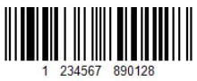
EAN-13: The European Article Numbering System (EAN) is a superset of U.P.C. EAN13 consists of 13 numbers.
UPC-A: The Universal Product Code (UPC) barcode is used in the retail industry. UPC-A consists of 12 numbers.
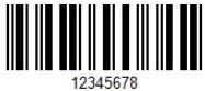
EAN-8: The European Article Numbering System (EAN) is a superset of U.P.C. EAN-8 and consists of 8 digits for small packages.
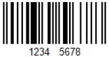
ITF: Interleaved 2 of 5 (ITF) is a numeric-only barcode used for encoding pairs of numbers in a high-density barcode format similar to code 128-character set C.
Code 39: The Code 39 barcode is the easiest to use of alpha-numeric barcodes and is designed for character self-checking, thus eliminating the requirement for check character calculations.
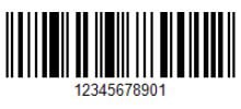
Code 128: A very effective, high-density symbology that permits the encoding of alphanumeric data. The symbology includes a checksum digit for verification, and the barcode may also be verified character-by-character verifying the parity of each data byte.
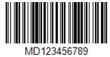
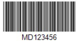
Mostly Code 128 is used as it can store alphanumeric data of certain lengths, so we are just taking out some random barcodes of code 128 for our project.
Circuit Diagram of Barcode Reader Interfacing with Raspberry Pi and LCD
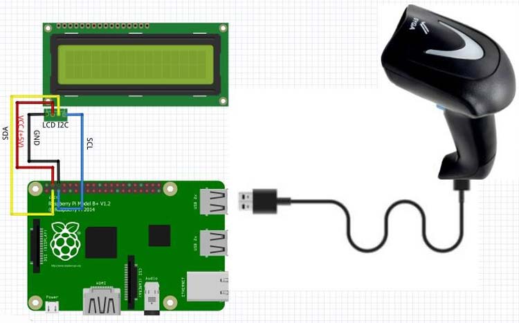
Here we will connect a 16X2 alphanumeric LCD with the Raspberry pi 4 in I2C mode and display the value of barcodes that were scanned by the barcode scanner.
The below image shows how the LCD and barcode scanner is connected with Raspberry Pi. Here, a representation of I2C has been given as it has 4 Wires for communication.
| I2C Pins | Raspberry Pi Pins |
|---|---|
| SDA | Pin No. 2 |
| SCL | Pin No. 3 |
| VCC | Pin No. 4 |
| GND | Pin No. 6 |
The above table is showing all the respective connections. Here we are considering PIN no layout for the Raspberry Pi and not the GPIO pin layout.
You can also refer to the following image for clear connections, where you can observe that all the pins are directly connected to the Raspberry Pi without any additional component like resistor or capacitor.

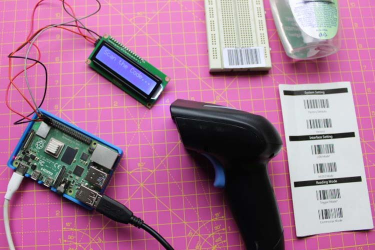
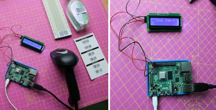
Let's have a look at what actually we are building. Here, you can see that we have generated some random barcodes and pasted them on different items such as a breadboard, sanitizer, etc. Also, you can see that there is a Setting page for our barcode scanner.
Enabling I2C on Raspberry Pi to interface LCD
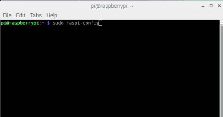
First, we should enable I2C in Raspberry Pi. We can enable it through the terminal command which is given below.
sudo raspi-config
Now, go to the Interfacing options by down Arrow Key and then, go to the P5 option i.e. I2C Enable/Disable option as follows.
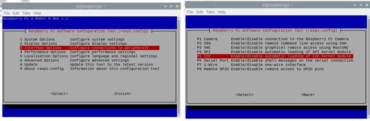
After that it will ask “would you like the ARM interface to be enabled?” press “<Yes>” and then it will be showing that “The ARM I2C interface is enabled.” Press <ok> and then press finish.
Before working on LCD, please check the I2C address of LCD which you are connecting with raspberry at python Terminal using the command
sudo i2cdetect -y 1
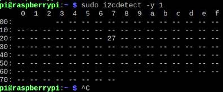
Here you can see that the address of the I2C device which is connected is 27.
Setting up Barcode Scanner
My Barcode scanner got shipped with this. This card will help us to customize some basic settings like Baud rate, Triggering mode, Factory default settings, etc. just by scanning the respective code.
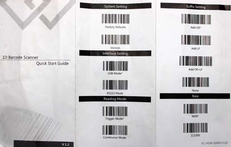
Before we start programming make sure that the mode of data transfer is USB mode. Also, make sure that the Reading mode is on Triggering mode and Suffix is CR*. A carriage return will always send an enter command at the end of the transmitted data set.
Programming Raspberry Pi to Read Barcode
Now download and install the rpi_LCD using pip, pip install rpi_ lcd using the shell of the pi. I am using VNC viewer to remotely operate my Raspberry Pi that is connected to the same wifi network as my laptop. Along with that, I programmed it using THONNY having python version 3.7.3. For the whole program, you can see at the bottom of this article.
In the Program, we are first importing Sleep object from Time because we will be using Delay for displaying the content on the LCD. After that, we will import the LCD object from the rpi_lcd for interfacing the 16X2 LCD.
from time import sleep
from rpi_lcd import LCD
After that we have declared a variable as item_count which is storing the no. of items scanned till the loop is executed. Initially, it is 0 for avoiding any garbage value. Similarly, scode will store the scanned barcode and initially, it is blank.
item_count=0   #For storing the no. of scanned items
scode="" #variable that will contain the scan code
lcd.text("Scan the Code... ", 1)   #welcome message that will display in first line of the display
Now in the while loop, we will be scanning endlessly until we reset the controller.
In this loop input() function will require data from the terminal which will be then stored in scode in String format. We are then printing it on the LCD display.
while 1:   #for Endless scans
    scode= str(input())  #will wait to get the input from barcode reader
    lcd.text("Scanned Barcode is", 1)
    lcd.text(scode,2)  #displaying Scanned Barcode on 2nd Row
    sleep(2)   #Delay of 2 seconds
    lcd.text("   Item Added", 1)
    sleep(2)
    item_count=item_count+1   #count and will increase the count every time it scan a barcode
    IC=str(item_count)   #type casting item_count from Integer to STRING
    lcd.text("  Total Item = ",1)
    lcd.text(IC,2)
    sleep(1)
Now while execution of the loop there will be an increment in the item_count which was 0 initially. Now the value of item_count is 1. For displaying this count on the LCD screen by using the lcd.text() function, we will convert item_count value from integer to string through typecasting. This will then be displayed on the LCD.
You can refer to the following images for better Understanding. The scanned barcode will be displayed for 2 seconds on LCD and then a message will show you that the ‘Item is added’, then after 2 seconds, you can see that the LCD will always be showing up the total count of the scanned items.
That’s all for today’s project. We will try to build it using an Arduino and at that time we will try out more modes of the barcode reader.
Complete Project Code
from time import sleep
from rpi_lcd import LCD
lcd = LCD() #inintialising the LCD by default it is for 16X2 alpha numeric Lcd
item_count=0   #For storing the no. of scanned items
scode="" #variable that will contain the scan code
lcd.text("Scan the Code... ", 1)   #welcome message that will display in first line of the display
while 1:   #for Endless scans
    scode= str(input())  #will wait to get the input from barcode reader
    lcd.text("Scanned Barcode is", 1)
    lcd.text(scode,2)  #displaying Scanned Barcode on 2nd Row
    sleep(2)   #Delay of 2 seconds
    lcd.text("   Item Added", 1)
    sleep(2)
    item_count=item_count+1   #count and will increase the count every time it scan a barcode
    IC=str(item_count)   #type casting item_count from Integer to STRING
    lcd.text("  Total Item = ",1)
    lcd.text(IC,2)
    sleep(1)