
This comprehensive guide shows you how to interface the HC-05 Bluetooth module with the ESP8266 NodeMCU using Arduino IDE. Nowadays, Bluetooth has become an integral part of digital devices, and it comes built-in in most of the devices such as smartphones, laptops, PC, cameras, Watches, Fitness Bands and many more. Bluetooth has always been the dominant protocol in wireless communication ever since it was discovered. Although Bluetooth Technology is fundamentally a cable replacement system, it also leverages a universal bridge to existing data networks and an ad hoc connection mechanism for a number of devices in various configurations. We have used Bluetooth module HC05 and HC06 with many other microcontrollers to make them communicate wirelessly:
- Interfacing Bluetooth HC-05 with STM32F103C8 Blue Pill: Controlling LED
- Interfacing the HC-05 Bluetooth module with the AVR Microcontroller
- Android Controlled Robot using 8051 Microcontroller
- Controlling Raspberry Pi GPIO using Android App over Bluetooth
- Bluetooth Controlled Toy Car using Arduino
Today, we will interface the HC-05 Bluetooth Module with the popular Wi-Fi module ESP8266 and control an LED wirelessly by sending commands via Bluetooth. This LED can be replaced by a Relay and an AC appliance to build a Home Automation Application.
Table of Contents
Components Required for ESP8266 Bluetooth Module Project
Hardware:
- NodeMCU ESP8266
- HC-05 Bluetooth Module
Software:
- Arduino IDE
- Serial Bluetooth Terminal (Android App): To Monitor Bluetooth Data on a Smartphone.
Why Use ESP8266 with an External Bluetooth Module?
While built-in Bluetooth Low Energy (BLE) and Classic Bluetooth are integrated features of the ESP32, you will need to use an external Bluetooth module like the HC-05 for the ESP8266 to allow wireless communication. Using these two devices together can be great for:
- Arduino Bluetooth projects that need both Wi-Fi and Bluetooth
- Low-cost IoT projects that need to use two wireless protocols
- Mobile app-controlled home automation
- Wireless sensor networks and remote monitoring
ESP8266 Bluetooth Module Wiring Diagram
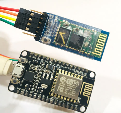
The circuit diagram to connect the Bluetooth module HC-05 with the NodeMCU ESP8266 is very simple and shown below:

The ESP8266 Bluetooth module wiring diagram below shows the complete connection between NodeMCU and HC-05
| HC-05 Pin | ESP8266 NodeMCU Pin | Function |
| VCC | 3.3V or 5V | Power Supply |
| GND | GND | Ground Connection |
| TXD | D2 (GPIO4) | Serial Transmit |
| RXD | D3 (GPIO0) | Serial Receive |
| EN | Not Connected | Enable Pin (Optional) |
| STATE | Not Connected | Connection Status |
An external Bluetooth module is needed with ESP8266, as it doesn’t have built-in Bluetooth like ESP32. ESP32 has built-in Bluetooth Low Energy (BLE) and Classic Bluetooth, on which we have previously covered a few tutorials:
- ESP32 BLE Server - GATT Service for Battery Level Indication
- ESP32 BLE Client – Connecting to a Fitness Band to Trigger a Bulb
- How to Use Serial Bluetooth in ESP32
Understanding HC-05 Bluetooth Module Specifications
The HC-05 Bluetooth module Arduino compatible device, offers these key features:
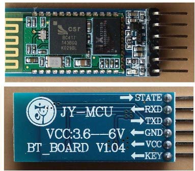
Pin Configuration Details
| Pin Name | Function | Description |
| VCC | Power | 3.3V to 5V supply voltage |
| GND | Ground | Common ground reference |
| TXD | Transmit | Serial data output from module |
| RXD | Receive | Serial data input to module |
| EN | Enable | Module enable/disable control |
| STATE | Status | Connection status indicator |
HC-05 is a serial Bluetooth module. It can be configured using AT commands. It can work in three different configurations (Master, Slave, Loopback). In our project, we will be using it as a slave. The features of the HC-05 module include.
- Typical -80dBm sensitivity.
- Default baud rate: 9600bps, 8 data bits, 1 stop bit, no parity.
- Auto-pairing pin code: “1234” or “0000” default pin code.
- It has 6 pins.
- Vcc and Gnd pins are used for powering the HC-05.
- Tx and Rx pins are used for communicating with the microcontroller.
- Enable the pin for activating the HC-05 module. When it is low, the module is disabled
- The state pin acts as a status indicator. When it is not paired/connected with any other Bluetooth device, the LED flashes continuously. When it is connected/paired with any other Bluetooth device, the LED flashes with a constant delay of 2 seconds.
To learn more about the Bluetooth module, go through our other Bluetooth-related projects.
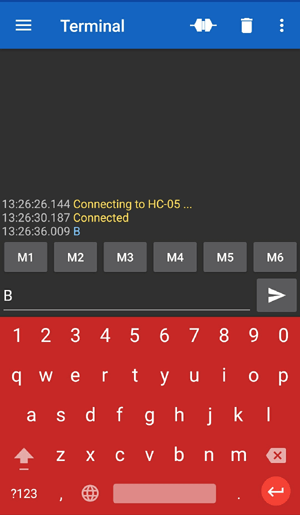
Using Serial Bluetooth Terminal (Android App)
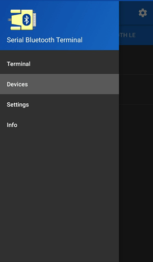
Using this app is very easy and requires a few steps. The screenshots are given below with the steps. Just pair the HC-05 with a Smartphone. The default code is ‘0000’ or ‘1234’, but mostly ‘1234’ works.
- Firstly, download and install the app. Then, go to devices to find the HC-05 Module. Select the HC-05 Module searched on the app. If not found, then check if the HC-05 is properly powered.

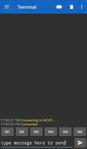
- After clicking the HC-05, it will get connected. Now type any message in the message box and send it. It will get printed on the Arduino Serial Monitor.
ESP8266 Bluetooth Module Arduino Programming
For programming the NodeMCU ESP8266 using Arduino IDE, just plug it into a Laptop or PC using a Micro USB Cable and open Arduino IDE. For this tutorial, the hardware serial and software serial will be used. The hardware serial will be used to read and write data to the Arduino Serial Monitor, and the software serial will be used to communicate with the HC-05. As always, complete code and Demo Video are given at the end of the tutorial.
Initially, include the Software Serial library since it will be used in this tutorial. Here's the complete ESP8266 Bluetooth example code for controlling the LED wirelessly:
#include <SoftwareSerial.h>
Define the RX and TX pins for software serial communication, and also define the LED pin connected to NodeMCU. We are using the internal LED of NodeMCU, which is at Pin D4.
SoftwareSerial btSerial(D2, D3); // RX,
int led = D4;
Start the Software and Hardware Serial at a 9600 baud rate. Set the LED pin as an output. Print some welcome and debug messages.
Serial.begin(9600);
btSerial.begin(9600);
pinMode(D4, OUTPUT);
Serial.println("Started...");
Firstly, read from the Bluetooth module and define a case that if the Bluetooth Module receives “B” from Phone, then Start Blinking LED connected to D4 of NodeMCU, else if it receives “S”, then stop blinking the LED. We are not using delay() here. But Arduino ‘millis’ will be used not to hamper the performance of Arduino.
 if (btSerial.available() > 0) {
    char data = btSerial.read();
    switch (data)
    {
      case 'B':
        ledB = "blink";
        break;
      case 'S':
        ledB = "stop";
        break;
      default:
        break;
    }
  }
The millis is defined and sets the delay to 500ms, i.e. the LED will blink after every 500ms. Also, you can configure the LED delay by changing the value of ‘interval’. The LED state will be toggled.
unsigned long currentMillis = millis();
  if (ledB == "blink") {
    Serial.println("blinking started");
    if (currentMillis - previousMillis >= interval) {
      previousMillis = currentMillis;
      if (ledState == LOW) {
        ledState = HIGH;
      } else {
        ledState = LOW;
      }
      digitalWrite(led, ledState);
    }
  }
And this will finish the programming of NodeMCU to blink the LED wirelessly using Bluetooth. You can also change the program to do different tasks with the LED, like replacing the LED with a Relay with an AC appliance to make a Bluetooth Home automation project.
Technical Summary and GitHub Repository
The Technical Summary provides a clear explanation of the project’s objective, working principle, and design flow, making it easy to understand the overall concept. The GitHub Repository complements this by offering complete source code, circuit diagrams, and documentation, ensuring users have all the necessary resources.


Troubleshooting Common Issues
| Issue | Possible Cause | Solution |
| HC-05 not discoverable | Power supply issue | Check 3.3V/5V connections and LED indicator |
| Cannot pair with phone | Wrong PIN code | Try "1234", "0000", or reset module |
| No data transmission | Wrong wiring | Check TX/RX cross-connections |
| LED not responding | Code or hardware issue | Test with Serial Monitor first |
Frequently Asked Questions Arduino Bluetooth Module
⇥ 1. Is HC-06 compatible with ESP8266 instead of HC-05?
Yes, HC-06 is used in the same way as HC-05 with ESP8266. The only difference is that HC-06 only supports slave mode and not master mode like HC-05.
⇥ 2. What is the maximum ESP8266 Bluetooth range?
The range of the HC-05 Bluetooth module is usually 10 meters in free space. Range could be lessened by obstacles, interference, and power supply quality.
⇥ 3. Why do we use SoftwareSerial rather than Hardware Serial?
ESP8266 hardware serial is employed for debugging and programming. SoftwareSerial provides another serial port for HC-05 communication without interference.
⇥ 4. Is it possible to control multiple devices from one Bluetooth configuration on the ESP8266?
Yes, multiple LEDs, relays, or sensors can be controlled by adding switch-case logic to the code for the different command characters.
⇥ 5. How do you set the baud rate of the HC-05 to a quicker rate?
You can set the HC-05 using AT commands: to set the baud rate to 115200, send "AT+UART=115200,0,0" . After you do this, you will want to change the code for Arduino, too.
⇥ 6. ESP8266 and ESP32 differ in what regards Bluetooth projects?
ESP32 comes with built-in Bluetooth/WiFi, but ESP8266 requires an external module for Bluetooth. ESP32 provides BLE and Classic Bluetooth with improved performance.
⇥ 7. How to make Bluetooth communication secure in this project?
You can use AT commands to change the default PIN code, you could add encryption to the code, and possibly use unique device names. If you can, add an authentication method.
⇥ 8. Which Arduino IDE version is best compatible with ESP8266?
The best compatibility comes from Arduino IDE 1.8.x or 2.x with ESP8266 board package 3.x.x. Download from Boards Manager using stable releases.
An ESP8266 Bluetooth module HC-05 tutorial gives full instructions for wireless control projects. Combining the Wi-Fi capabilities of ESP8266 with the Bluetooth features of HC-05 can provide innumerable Arduino Bluetooth projects and IoT possibilities. Thus, the ESP8266 Bluetooth module wiring diagram and Arduino programming code create a solid foundation for more complex projects. Whether you're building home automation systems, the code laid out here can be used as a framework for more complex projects.
In case of any doubt or suggestion, please reach out to our forum or comment below.
Innovative Projects using Bluetooth
For a deeper understanding of how these Bluetooth devices are applied, explore the project links listed below.

Interfacing the HC-05 Bluetooth Module with the MSP430 Launchpad to control an LED
Today, we will learn to interface the Bluetooth module HC-05 with the MSP430 Launchpad from Texas Instruments. In this interfacing example, we will control the on-board LED of MSP430 from the smartphone by using a Bluetooth Terminal Android application.

How to Use Classic Serial Bluetooth in ESP32
After a long time of surfing and YouTubeing, I realised that there are a lot more things to understand if you have to work with Bluetooth Low Energy (BLE) using ESP32. I decided to cover the BLE in separate articles, so here we will use the Classic Serial Bluetooth of ESP32 to toggle an LED using a smartphone.

Getting Started with Bluetooth Classic on ESP32
Using the ESP32's internal Bluetooth Classic module can be advantageous because it allows developers to easily incorporate Bluetooth Classic functionality into their projects without the need for an external module. This can simplify the design process and reduce costs, while still providing a reliable and high-performing Bluetooth Classic connection.
Complete Project Code
/* HC-05 interfacing with NodeMCU ESP8266
    Author: Circuit Digest(circuitdigest.com)
*/
#include <SoftwareSerial.h>
SoftwareSerial btSerial(D2, D3); // Rx,Tx
int led = D4;   // led also the internal led of NodemCU
int ledState = LOW;   // led state to toggle
String ledB = "";
unsigned long previousMillis = 0;  // millis instaed of delay
const long interval = 500;  // blink after ecery 500ms
void setup() {
  delay(1000);
  Serial.begin(9600);
  btSerial.begin(9600);     // bluetooth module baudrate
  pinMode(D4, OUTPUT);
  Serial.println("Started...");
}
void loop() {
  if (btSerial.available() > 0) {    // check if bluetooth module sends some data to esp8266
    char data = btSerial.read();  // read the data from HC-05
    switch (data)
    {
      case 'B':         // if receive data is 'B'
        ledB = "blink";   // write the string
        break;
      case 'S':              // if receive data is 'S'
        ledB = "stop";
        break;
      default:
        break;
    }
  }
  unsigned long currentMillis = millis();
  if (ledB == "blink") {          // if received data is 'B' the start blinking
    Serial.println("blinking started");
    if (currentMillis - previousMillis >= interval) {
      previousMillis = currentMillis;
      if (ledState == LOW) {
        ledState = HIGH;
      } else {
        ledState = LOW;
      }
      digitalWrite(led, ledState);
    }
  }
}
Comments
Is it possible to set this bodule to 7 data bits.

Can I combine the code of Bluetooth condition into blynk code for nodemcu?