
In this tutorial let us learn How to interface HC-05 Bluetooth Module with AVR ATmega8 microcontroller. We will establish communication between Android mobile and Atmega8 through Bluetooth module which takes place through UART serial communication protocol. In this project we will control a LED using Bluetooth of our smartphone.
Material Required:
- AVR Atmega8
- HC-05 Bluetooth module
- LED
- USBASP programmer
- 10-pin FRC cable
- Jumper wires
- Breadboard
Software Used:
We will use CodeVisionAVR software for writing our code and SinaProg software for uploading our code to Atmega8 using USBASP programmer.
You can download these softwares from the given links:
CodeVisionAVR : http://www.hpinfotech.ro/cvavr_download.html
Bluetooth Module HC-06:
Bluetooth can operate in the following two modes:
- Command Mode
- Operating Mode
In Command Mode we will be able to configure the Bluetooth properties like the name of the Bluetooth signal, its password, the operating baud rate etc. The Operating Mode is the one in which we will be able to send and receive data between the PIC Microcontroller and the Bluetooth module. Hence in this tutorial we will be toying only with the Operating Mode. The Command mode will be left to the default settings. The Device name will be HC-05 (I am using HC-06) and the password will be 0000 or 1234 and most importantly the default baud rate for all Bluetooth modules will be 9600.
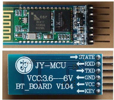
The module works on 5V supply and the signal pins operate on 3.3V, hence a 3.3V regulator is present in the module itself. Hence we need not worry about it. Out of the six pins only four will be used in the Operating mode. The pin connection table is shown below
|
S.No |
Pin on HC-05/HC-06 |
Pin name on MCU |
Pin number in PIC |
|
1 |
Vcc |
Vdd |
31st pin |
|
2 |
Vcc |
Gnd |
32nd pin |
|
3 |
Tx |
RC6/Tx/CK |
25th pin |
|
4 |
Rx |
RC7/Rx/DT |
26th pin |
|
5 |
State |
NC |
NC |
|
6 |
EN (Enable) |
NC |
NC |
Check our other projects to learn more about Bluetooth module HC-05 with other microcontrollers:
- Bluetooth Controlled Toy Car using Arduino
- Bluetooth Controlled Home Automation System using 8051
- Controlling Raspberry Pi GPIO using Android App over Bluetooth
- Smart Phone Controlled FM Radio using Arduino and Processing
- Mobile Phone Controlled Robot Car using G-Sensor and Arduino
Creating the Project for Atmega 8 using CodeVision:
After installing these softwares follow the below steps to create project and writing code:
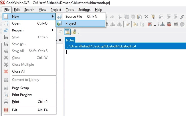
Step 1. Open CodeVision Click on File -> New -> Project. Confirmation Dialogue box will appear. Click On Yes
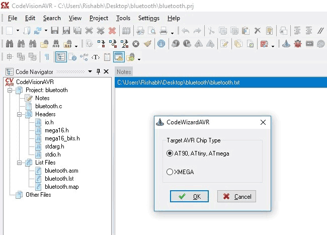
Step 2. CodeWizard will open. Click on first option i.e. AT90, and click OK.
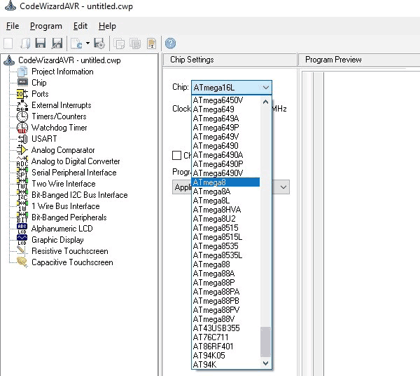
Step 3. Choose your microcontroller chip, here we will take Atmega8 as shown.
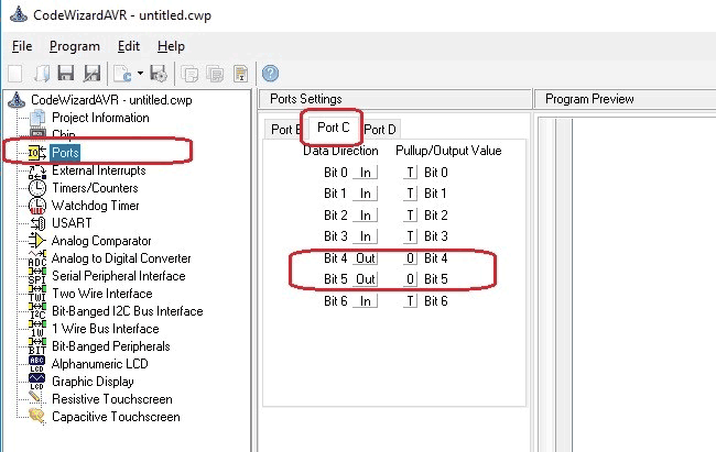
Step 4. Click on Ports. In our project, we will be using Port C4 and C5 for led interfacing. So, make Bit 4 and bit 5 as output by clicking on it. As shown below:
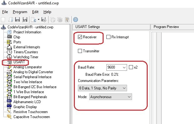
Step 5. We will use USART for Rx and Tx. So, click on USART option and click on Receiver option and leave rest as it is.
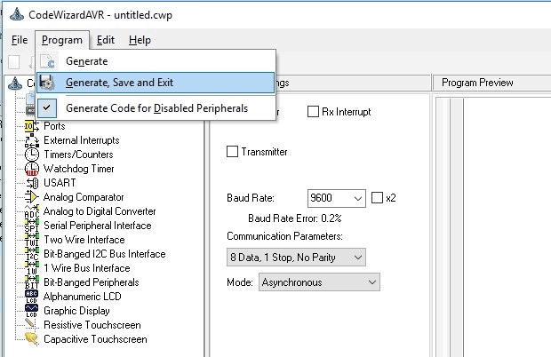
Step 6. Click on Program -> Generate, Save and Exit. Now, more than half of our work is completed
Step 7. Make a New folder on desktop so, that our files remains in folder otherwise it we will be scattered on whole desktop window. Name your folder as you want and I suggest use the same name to save program files.
We will be having three dialogues box one after other to save files.
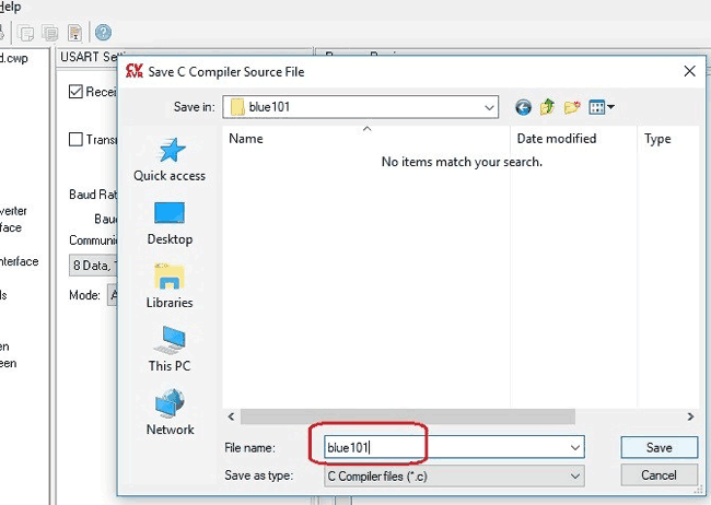
Do the same with other two dialogue boxes which will appear after you save the first.
Now, your workspace looking like this.
Our most of the work is completed with the help of the Wizard. Now, we have to write only few lines of code to interface the bluetooth module and control the LED.
Circuit Diagram:
Circuit diagram for interfacing Bluetooth HC-05 with AVR is given below.

Hookup the one side of FRC cable to USBASP programmer and other side will connect to SPI pins of microcontroller as described below:
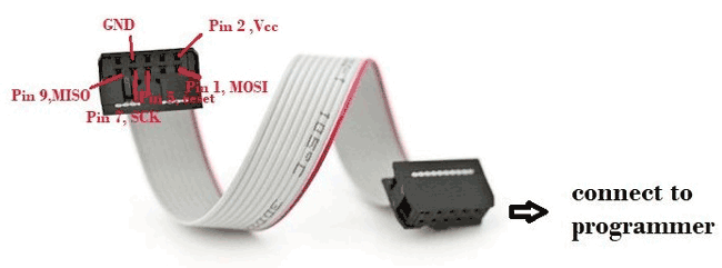
- Pin1 of FRC female connector -> Pin 17 ,MOSI of Atmega8
- Pin 2 connected to Vcc of atmega8 i.e. Pin 7
- Pin 5 connected to Reset of atmega8 i.e. Pin 1
- Pin 7 connected to SCK of atmega8 i.e. Pin 19
- Pin 9 connected to MISO of atmega8 i.e. Pin 18
- Pin 8 connected to GND of atmega8 i.e. Pin 8
Connect the remaining components on the breadboard as per circuit diagram.
Code and Explanation:
Complete AVR code with Demonstration Video is given at the end of the article.
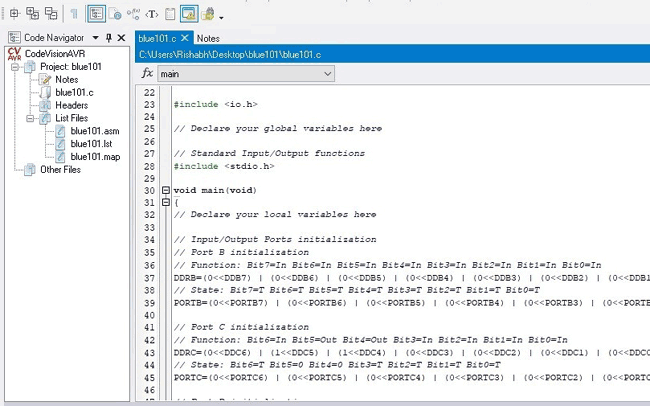
Here we have declared a variable in void main function for storing incoming character from Bluetooth module.
#include <io.h>
// Declare your global variables here
// Standard Input/Output functions
#include <stdio.h>
void main(void)
{
char var;                 // Declare your local variables here
Rest of the code is easy and can be easily understandable. Now, come on the last lines of code where you will find a while loop. Our main code will be in this loop. Here we are continuously checking the incoming character from the Bluetooth module and turning the LED On or off accordingly.
while (1)
      {
       scanf("%c",&var);               //this function is to used to check any character coming from our android app .
      if (var == 'a')                              // We will send ‘a’ from Bluetooth Terminal to ON the LED and ‘b’ to OFF the LED
      {
            PORTC.5 = 1;
            PORTC.4 = 0;
      }
          if (var == 'b')
      {
            PORTC.5 = 0;
            PORTC.4 = 0;
      }
      }
Our code is completed. Now, we have to build our project. Click on Build the project icon as shown.
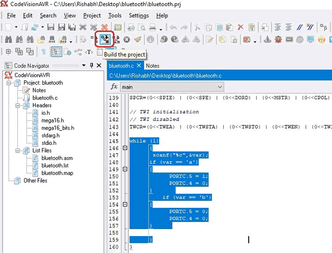
After building the project, a HEX file is generated in the Debug-> Exe folder which can be found in the folder you make previously to save your project. We will use this HEX file to upload in atmega8 using Sinaprog software.
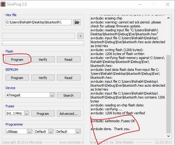
Uploading the code to Atmega 8 using Sinaprog:
We will upload the above generated Hex file using the Sinaprog, so open it and Choose Atmega8 from Device drop down menu. Select the HEX file from the Debug-> Exe folder as shown.
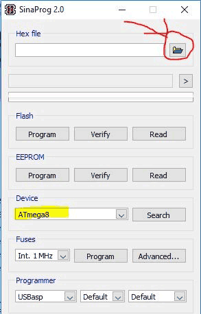
Now, Click on Program.
Your Microcontroller is programmed. Now, we need an Android app to connect with our module. We will use “Bluetooth Terminal app” to control the LED light.
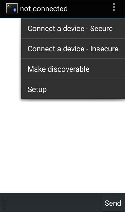
Android App for controlling LED using AVR:
We will use “Bluetooth Terminal app” in our smart phone to talk to the HC-05 at the other end to control the LED light. This app can be downloaded from given link:
https://play.google.com/store/apps/details?id=Qwerty.BluetoothTerminal&hl=en_IN
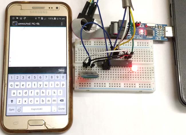
You can power up your circuit using the same usbasp by plugging it into your PC or you can apply external 5V (not more than 5!!!!!) to the Atmega8 Vcc pin.
After installing it .Open the app and connect it with Bluetooth module (HC-05 and default password is 1234).
Now, send ‘a’ and see the led will glow. Send ‘b’, led will off.
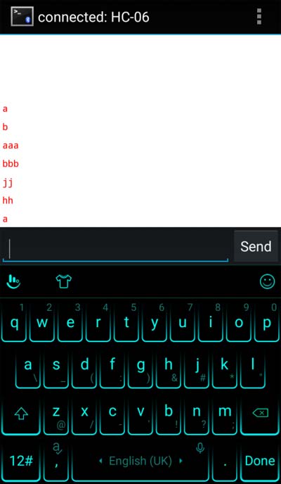
So now by sending the character ‘a’ and ‘b’, you can control the LED wirelessly using your Smartphone. And if you use the voice keyboard with Bluetooth app then you don’t even need to type the character ‘a’ and ‘b’, you can just speak them and can control the LED using your voice.
Complete Project Code
#include <io.h>
#include <stdio.h>
void main(void)
{
char var;
// Declare your local variables here
// Input/Output Ports initialization
// Port A initialization
// Function: Bit7=In Bit6=In Bit5=In Bit4=In Bit3=In Bit2=In Bit1=In Bit0=In
DDRA=(0<<DDA7) | (0<<DDA6) | (0<<DDA5) | (0<<DDA4) | (0<<DDA3) | (0<<DDA2) | (0<<DDA1) | (0<<DDA0);
// State: Bit7=T Bit6=T Bit5=T Bit4=T Bit3=T Bit2=T Bit1=T Bit0=T
PORTA=(0<<PORTA7) | (0<<PORTA6) | (0<<PORTA5) | (0<<PORTA4) | (0<<PORTA3) | (0<<PORTA2) | (0<<PORTA1) | (0<<PORTA0);

// Port B initialization
// Function: Bit7=In Bit6=In Bit5=In Bit4=In Bit3=In Bit2=In Bit1=In Bit0=In
DDRB=(0<<DDB7) | (0<<DDB6) | (0<<DDB5) | (0<<DDB4) | (0<<DDB3) | (0<<DDB2) | (0<<DDB1) | (0<<DDB0);
// State: Bit7=T Bit6=T Bit5=T Bit4=T Bit3=T Bit2=T Bit1=T Bit0=T
PORTB=(0<<PORTB7) | (0<<PORTB6) | (0<<PORTB5) | (0<<PORTB4) | (0<<PORTB3) | (0<<PORTB2) | (0<<PORTB1) | (0<<PORTB0);

// Port C initialization
// Function: Bit7=In Bit6=In Bit5=Out Bit4=Out Bit3=In Bit2=In Bit1=In Bit0=In
DDRC=(0<<DDC7) | (0<<DDC6) | (1<<DDC5) | (1<<DDC4) | (0<<DDC3) | (0<<DDC2) | (0<<DDC1) | (0<<DDC0);
// State: Bit7=T Bit6=T Bit5=0 Bit4=0 Bit3=T Bit2=T Bit1=T Bit0=T
PORTC=(0<<PORTC7) | (0<<PORTC6) | (0<<PORTC5) | (0<<PORTC4) | (0<<PORTC3) | (0<<PORTC2) | (0<<PORTC1) | (0<<PORTC0);

// Port D initialization
// Function: Bit7=In Bit6=In Bit5=In Bit4=In Bit3=In Bit2=In Bit1=In Bit0=In
DDRD=(0<<DDD7) | (0<<DDD6) | (0<<DDD5) | (0<<DDD4) | (0<<DDD3) | (0<<DDD2) | (0<<DDD1) | (0<<DDD0);
// State: Bit7=T Bit6=T Bit5=T Bit4=T Bit3=T Bit2=T Bit1=T Bit0=T
PORTD=(0<<PORTD7) | (0<<PORTD6) | (0<<PORTD5) | (0<<PORTD4) | (0<<PORTD3) | (0<<PORTD2) | (0<<PORTD1) | (0<<PORTD0);

// Timer/Counter 0 initialization
// Clock source: System Clock
// Clock value: Timer 0 Stopped
// Mode: Normal top=0xFF
// OC0 output: Disconnected
TCCR0=(0<<WGM00) | (0<<COM01) | (0<<COM00) | (0<<WGM01) | (0<<CS02) | (0<<CS01) | (0<<CS00);
TCNT0=0x00;
OCR0=0x00;

// Timer/Counter 1 initialization
// Clock source: System Clock
// Clock value: Timer1 Stopped
// Mode: Normal top=0xFFFF
// OC1A output: Disconnected
// OC1B output: Disconnected
// Noise Canceler: Off
// Input Capture on Falling Edge
// Timer1 Overflow Interrupt: Off
// Input Capture Interrupt: Off
// Compare A Match Interrupt: Off
// Compare B Match Interrupt: Off
TCCR1A=(0<<COM1A1) | (0<<COM1A0) | (0<<COM1B1) | (0<<COM1B0) | (0<<WGM11) | (0<<WGM10);
TCCR1B=(0<<ICNC1) | (0<<ICES1) | (0<<WGM13) | (0<<WGM12) | (0<<CS12) | (0<<CS11) | (0<<CS10);
TCNT1H=0x00;
TCNT1L=0x00;
ICR1H=0x00;
ICR1L=0x00;
OCR1AH=0x00;
OCR1AL=0x00;
OCR1BH=0x00;
OCR1BL=0x00;

// Timer/Counter 2 initialization
// Clock source: System Clock
// Clock value: Timer2 Stopped
// Mode: Normal top=0xFF
// OC2 output: Disconnected
ASSR=0<<AS2;
TCCR2=(0<<PWM2) | (0<<COM21) | (0<<COM20) | (0<<CTC2) | (0<<CS22) | (0<<CS21) | (0<<CS20);
TCNT2=0x00;
OCR2=0x00;

// Timer(s)/Counter(s) Interrupt(s) initialization
TIMSK=(0<<OCIE2) | (0<<TOIE2) | (0<<TICIE1) | (0<<OCIE1A) | (0<<OCIE1B) | (0<<TOIE1) | (0<<OCIE0) | (0<<TOIE0);

// External Interrupt(s) initialization
// INT0: Off
// INT1: Off
// INT2: Off
MCUCR=(0<<ISC11) | (0<<ISC10) | (0<<ISC01) | (0<<ISC00);
MCUCSR=(0<<ISC2);

// USART initialization
// Communication Parameters: 8 Data, 1 Stop, No Parity
// USART Receiver: On
// USART Transmitter: Off
// USART Mode: Asynchronous
// USART Baud Rate: 9600
UCSRA=(0<<RXC) | (0<<TXC) | (0<<UDRE) | (0<<FE) | (0<<DOR) | (0<<UPE) | (0<<U2X) | (0<<MPCM);
UCSRB=(0<<RXCIE) | (0<<TXCIE) | (0<<UDRIE) | (1<<RXEN) | (0<<TXEN) | (0<<UCSZ2) | (0<<RXB8) | (0<<TXB8);
UCSRC=(1<<URSEL) | (0<<UMSEL) | (0<<UPM1) | (0<<UPM0) | (0<<USBS) | (1<<UCSZ1) | (1<<UCSZ0) | (0<<UCPOL);
UBRRH=0x00;
UBRRL=0x33;

// Analog Comparator initialization
// Analog Comparator: Off
// The Analog Comparator's positive input is
// connected to the AIN0 pin
// The Analog Comparator's negative input is
// connected to the AIN1 pin
ACSR=(1<<ACD) | (0<<ACBG) | (0<<ACO) | (0<<ACI) | (0<<ACIE) | (0<<ACIC) | (0<<ACIS1) | (0<<ACIS0);
SFIOR=(0<<ACME);

// ADC initialization
// ADC disabled
ADCSRA=(0<<ADEN) | (0<<ADSC) | (0<<ADATE) | (0<<ADIF) | (0<<ADIE) | (0<<ADPS2) | (0<<ADPS1) | (0<<ADPS0);

// SPI initialization
// SPI disabled
SPCR=(0<<SPIE) | (0<<SPE) | (0<<DORD) | (0<<MSTR) | (0<<CPOL) | (0<<CPHA) | (0<<SPR1) | (0<<SPR0);

// TWI initialization
// TWI disabled
TWCR=(0<<TWEA) | (0<<TWSTA) | (0<<TWSTO) | (0<<TWEN) | (0<<TWIE);

while (1)
      {
       scanf("%c",&var);
      if (var == 'a')
      {
            PORTC.5 = 1;
            PORTC.4 = 0;
      }
          if (var == 'b')
      {
            PORTC.5 = 0;
            PORTC.4 = 0;
      }

      }
}

Hello. I followed the code, but my LED does not turn on off.
I added this line to make sure that my HC06 received data from android
scanf("%c",&c); PORTC.7=1 // Led 7 turned on after input from android phone.
But the received 'var' does not the same with the letter sent from phone. So my led can't turn on after 'a' or off after 'b'.
I'm using atmega16, 8Mhz Clock (not sure if it need to enable fuse bit clock, just default in Progisp //a programmer softawre like Sinaprog.
Thank a lot